EP0940339A1 - Continuous product wrapping method and machine - Google Patents
Continuous product wrapping method and machine Download PDFInfo
- Publication number
- EP0940339A1 EP0940339A1 EP99104385A EP99104385A EP0940339A1 EP 0940339 A1 EP0940339 A1 EP 0940339A1 EP 99104385 A EP99104385 A EP 99104385A EP 99104385 A EP99104385 A EP 99104385A EP 0940339 A1 EP0940339 A1 EP 0940339A1
- Authority
- EP
- European Patent Office
- Prior art keywords
- sheet
- seat
- spindle
- wrapping
- machine
- Prior art date
- Legal status (The legal status is an assumption and is not a legal conclusion. Google has not performed a legal analysis and makes no representation as to the accuracy of the status listed.)
- Granted
Links
- 238000000034 method Methods 0.000 title claims abstract description 21
- 239000000463 material Substances 0.000 claims abstract description 59
- 230000010355 oscillation Effects 0.000 claims 1
- 238000004804 winding Methods 0.000 claims 1
- 235000019504 cigarettes Nutrition 0.000 description 18
- 238000012546 transfer Methods 0.000 description 10
- 238000012856 packing Methods 0.000 description 9
- 239000011888 foil Substances 0.000 description 6
- 238000004049 embossing Methods 0.000 description 3
- 230000002093 peripheral effect Effects 0.000 description 3
- 238000003780 insertion Methods 0.000 description 2
- 230000037431 insertion Effects 0.000 description 2
- 230000002028 premature Effects 0.000 description 2
- 241000826860 Trapezium Species 0.000 description 1
- 230000008878 coupling Effects 0.000 description 1
- 238000010168 coupling process Methods 0.000 description 1
- 238000005859 coupling reaction Methods 0.000 description 1
- 230000001419 dependent effect Effects 0.000 description 1
- 238000013461 design Methods 0.000 description 1
- 239000002184 metal Substances 0.000 description 1
- 230000000149 penetrating effect Effects 0.000 description 1
- 230000000717 retained effect Effects 0.000 description 1
Images
Classifications
-
- B—PERFORMING OPERATIONS; TRANSPORTING
- B65—CONVEYING; PACKING; STORING; HANDLING THIN OR FILAMENTARY MATERIAL
- B65B—MACHINES, APPARATUS OR DEVICES FOR, OR METHODS OF, PACKAGING ARTICLES OR MATERIALS; UNPACKING
- B65B19/00—Packaging rod-shaped or tubular articles susceptible to damage by abrasion or pressure, e.g. cigarettes, cigars, macaroni, spaghetti, drinking straws or welding electrodes
- B65B19/02—Packaging cigarettes
- B65B19/22—Wrapping the cigarettes; Packaging the cigarettes in containers formed by folding wrapping material around formers
- B65B19/223—Wrapping the cigarettes; Packaging the cigarettes in containers formed by folding wrapping material around formers in a curved path; in a combination of straight and curved paths, e.g. on rotary tables or other endless conveyors
- B65B19/225—Wrapping the cigarettes; Packaging the cigarettes in containers formed by folding wrapping material around formers in a curved path; in a combination of straight and curved paths, e.g. on rotary tables or other endless conveyors the conveyors having continuous movement
-
- B—PERFORMING OPERATIONS; TRANSPORTING
- B65—CONVEYING; PACKING; STORING; HANDLING THIN OR FILAMENTARY MATERIAL
- B65B—MACHINES, APPARATUS OR DEVICES FOR, OR METHODS OF, PACKAGING ARTICLES OR MATERIALS; UNPACKING
- B65B11/00—Wrapping, e.g. partially or wholly enclosing, articles or quantities of material, in strips, sheets or blanks, of flexible material
- B65B11/06—Wrapping articles, or quantities of material, by conveying wrapper and contents in common defined paths
- B65B11/28—Wrapping articles, or quantities of material, by conveying wrapper and contents in common defined paths in a curved path, e.g. on rotary tables or turrets
- B65B11/30—Wrapping articles, or quantities of material, by conveying wrapper and contents in common defined paths in a curved path, e.g. on rotary tables or turrets to fold the wrappers in tubular form about contents
Definitions
- the present invention relates to a continuous product wrapping method.
- Cigarette packing machines are known to feature a step-operated or continuous wrapping wheel having a number of peripheral seats, each for receiving a respective group of cigarettes - normally comprising twenty cigarettes arranged in three layers - which is fed to a respective seat on the wrapping wheel from a respective seat on a transfer wheel.
- a sheet of foil is fed between the wheels along the transfer path of the group from one wheel to the other, so that, when transferring the group, the sheet is inserted inside the respective seat on the wrapping wheel and simultaneously folded into a U about the group.
- US Patent No. 5,392,586 describes a continuous wrapping unit operating according to the above known method, but which is complex in design and therefore expensive to produce. That is, the continuous movement of the wheels and the continually-changing positions of the seats with respect to each other and to the sheet of wrapping material call for complex mechanical solutions to keep the seats facing each other, and for synchronously inserting the sheet of wrapping material between the seats.
- the above method fails to provide for effectively folding the sheet of foil, on account of the increasingly fast operating speeds of modern packing machines - by now capable of producing over ten packets a second - reducing the folding time per sheet to a few hundredths of a second, and so stressing the sheet as to result in premature partial to total tearing of the tear-off portion.
- GB patent application No. 2138382 discloses a continuos cigarette packing machine having a conveyor supporting a plurality of seats, each of which is capable of receiving and conveying a relevant sheet of wrapping material and a respective group of cigarettes.
- the conveyor feeds each seat through a first loading station, in which the seat receives the relevant sheet of wrapping material, and a successive second loading station, in which the seat receives the relevant product.
- Each sheet of wrapping material is fed to the relevant seat by a respective folding spindle, which is fed through an output of a line for supplying wrapping material to pick up and fold the sheet of wrapping material at least partly into a U.
- the folding spindle is then fed through the first loading station to be inserted into the relevant seat for feeding the sheet arranged in a substantially U-folded configuration inside the relevant seat.
- a method of continuously wrapping a product comprising the steps of feeding a sheet of wrapping material to an output of a line for supplying wrapping material; coupling said sheet with a folding spindle, about which said sheet is folded at least partly into a U; feeding said folding spindle together with said sheet to a first loading station; inserting, at said first loading station said folding spindle into a seat on a wrapping conveyor for feeding the sheet arranged in a substantially U-folded configuration inside said seat; feeding the seat and the sheet through a second loading station to receive said product; and feeding the seat together with the sheet and the product through at least one folding station to fold said sheet about said product; the method being characterized in that said seat is set in a first open position, in which each of the said lateral walls forms with said bottom wall an obtuse angle, to receive said sheet and said product and in a second closed position, in which each of the said lateral walls forms with said bottom wall a substantially right angle, to hold together said sheet and said
- the present invention also relates to a machine for continuously wrapping a product.
- a machine for continuously wrapping a product comprising a line for supplying wrapping material and having an output; at least one seat for receiving and conveying said sheet of wrapping material and a respective product; a wrapping conveyor carrying said seat and having a first loading station for a sheet of wrapping material, a second loading station for said product, located downstream from said first loading station in a traveling direction of said seat, and at least one folding station to fold said sheet about said product; at least one folding spindle; and first actuating means for feeding the folding spindle through said output to pick up and fold said sheet of wrapping material at least partly into a U about the folding spindle, and then through said first loading station to insert said folding spindle into said seat for feeding the sheet arranged in a substantially U-folded configuration inside said seat; the machine being characterized in that said two lateral walls are rotary connected to said bottom wall; the machine further comprising second actuating means for setting said seat in a first open position, in which each of the said lateral walls forms with
- the additional features set out in Claims 3 and 12 allow a very good "U" folding of each sheet in the relevant seat. Furthermore, the additional feature set out in Claim 6 substantially allows canceling residual creeping of the external surfaces of the spindle with the internal surfaces of the seat.
- Number 1 in Figure 1 indicates as a whole an automatic packing machine for producing packets of cigarettes (not shown), wherein a group 2 of cigarettes is first wrapped in a sheet 3 of foil wrapping material, and is then inserted inside a blank (not shown) which is folded about group 2 to form a packet of cigarettes (not shown).
- Packing machine 1 comprises a wrapping wheel 4 powered to rotate continuously (clockwise in Figure 1) about a central axis 5 perpendicular to the Figure 1 plane, and having a number of peripheral seats 6 equally spaced about axis 5.
- Each seat 6 provides for receiving and conveying first a respective sheet 3 of wrapping material folded substantially into a U, and then also a respective group 2 of cigarettes, which is wrapped in sheet 3 of wrapping material.
- Packing machine 1 also comprises a supply device 7 for successively feeding sheets 3 of wrapping material to respective seats 6 on wrapping wheel 4 at a loading station 8; a known loading station 9 where groups 2 of cigarettes are fed successively to respective seats 6 on wrapping wheel 4; two known folding devices 10 and 11 for folding a sheet 3 of wrapping material about a respective group 2 of cigarettes at respective folding stations 12 and 13; and an unloading station 14 where groups 2 wrapped in respective sheets 3 of wrapping material are extracted successively from respective seats 6 on wrapping wheel 4 and fed to successive known wrapping units (not shown).
- a supply device 7 for successively feeding sheets 3 of wrapping material to respective seats 6 on wrapping wheel 4 at a loading station 8
- a known loading station 9 where groups 2 of cigarettes are fed successively to respective seats 6 on wrapping wheel 4
- two known folding devices 10 and 11 for folding a sheet 3 of wrapping material about a respective group 2 of cigarettes at respective folding stations 12 and 13
- an unloading station 14 where groups 2 wrapped in respective sheets 3 of wrapping material are extracted successively from respective seats 6 on wrapping wheel 4 and fed to
- Supply device 7 comprises a transfer wheel 15 powered to rotate continuously (anticlockwise in Figure 1) about a central axis 16 parallel to axis 5, and having a number of peripheral folding spindles 17 equally spaced about axis 16.
- Each folding spindle 17 provides for picking up a respective sheet 3 of wrapping material from a known supply unit 18, at an output of unit 18 defined by a supply station 19, and for feeding sheet 3 of wrapping material to a respective seat 6 at loading station 8.
- Supply device 7 also comprises a folding element P located along the path of folding spindles 17 between supply station 19 and loading station 8.
- Supply unit 18 comprises a known unwinding station 20 where a strip 21 of foil is unwound off a reel 22 supported on a pin 23; a known embossing station 24 having two embossing rollers 25; two feed rollers 26 for feeding strip 21 along supply unit 18; and a known cutting station 27 having two cutting rollers 28.
- folding spindles 17 are connected to transfer wheel 15 via the interposition of respective rocker arms 29, each of which is hinged to transfer wheel 15 to swing, with respect to transfer wheel 15, about an axis 30 parallel to axis 16.
- Each rocker arm 29 comprises a first arm 31 extending towards axis 16 and fitted on the free end with a tappet roller 32 connected to a fixed cam 33 defining, with roller 32, a control device 34 for controlling the angular position of rocker arm 29 about respective axis 30; and a second arm 35 extending outwards of transfer wheel 15 and fitted on the free end with a respective folding spindle 17.
- Each folding spindle 17 is substantially trapezoidal and is defined by a large bottom surface 36 parallel to axis 16, by a small top surface 37 parallel to surface 36 and outwards of surface 36 with respect to axis 16, and by two inclined lateral surfaces 38 and 39 located respectively at the front and rear with reference to the traveling direction of folding spindle 17, and which form, with top surface 37, two edges 40 parallel to axis 16.
- Each folding spindle 17 is fixed to respective arm 35 at bottom surface 36, and comprises a known pneumatic suction device 41, which comes out through a number of suction holes 42 formed in surfaces 37 and 38 to retain a respective sheet 3 of wrapping material.
- Each folding spindle 17 comprises an inner body 43 of nondeformable material, typically metal, covered at surfaces 37, 38 and 39 by a thin outer layer 44 of deformable material, typically rubber or sponge. In an alternative embodiment not shown, folding spindles 17 have no outer layers 44 of deformable material.
- Each folding spindle 17 also comprises a gripper 45 hinged to bottom surface 36 to retain a respective sheet 3 of wrapping material on lateral surface 38.
- each seat 6 is defined on a respective support 46 connected to wrapping wheel 4 via the interposition of a respective rocker arm 47 hinged to wrapping wheel 4 to swing, with respect to wrapping wheel 4, about an axis 48 parallel to axis 5.
- Each rocker arm 47 comprises a first arm 49 extending towards axis 5 and fitted on the free end with a tappet roller 50 connected to a fixed cam 51 defining, with roller 50, a control device 52 for controlling the angular position of rocker arm 47 about respective axis 48; and a second arm 53 extending outwards of wrapping wheel 4 and fitted on the free end with a respective support 46.
- Each seat 6 in respective support 46 is defined by a bottom wall 54 fitted to respective arm 53, and by two lateral walls 55 hinged on opposite sides of wall 54 to swing, about respective axes 56 parallel to axis 5, between an open position and a closed position.
- the two lateral walls 55 of each seat 6 In the open position, the two lateral walls 55 of each seat 6 form an obtuse angle with bottom wall 54, and the section of seat 6 is in the form of an isosceles trapezium negatively reproducing the shape of folding spindle 17.
- the two lateral walls 55 of each seat 6 form a substantially right angle with bottom wall 54, and seat 6 has a substantially rectangular section of substantially the same dimensions as a group 2 of cigarettes.
- a control device 57 comprising two first arms 58, each of which has one end fitted to a respective lateral wall 55, and the other end hinged to one end of a second arm 59.
- the other end of each arm 59 is hinged to a tubular body 60, which slides along respective arm 53 and comprises an appendix 61, to the free end of which is hinged a tappet roller 62 connected to a fixed cam 63 to control the sliding movement of body 60 along respective arm 53.
- the inner surfaces of walls 54 and 55 comprise a number of holes (not shown) connected to a known suction device (not shown) carried by wrapping wheel 4.
- folding device 10 comprises a cylinder 64 rotating about a fixed axis 65 parallel to axis 5; and a pair of folding elements 66 hinged to cylinder 64, and which are swung by a known cam control device (not shown) to fold a sheet 3 of wrapping material longitudinally about a respective group 2 of cigarettes.
- folding device 11 comprises a cylinder 67 rotating about a fixed axis 68 parallel to axis 5; and two pairs of folding elements 69 (only one shown in Figure 5) hinged to cylinder 67, and which are swung by a known cam control device (not shown) to fold both ends (only one shown in Figure 5) of a sheet 3 of wrapping material about a respective group 2 of cigarettes.
- packing machine 1 Operation of packing machine 1 will now be described with reference to one folding spindle 17 and one corresponding seat 6, and as of the instant in which folding spindle 17 is brought into supply station 19 by transfer wheel 15 rotating about axis 16.
- sheet 3 of wrapping material is embossed in known manner by embossing rollers 25, and is worked by a first pair of blades (not shown) on cutting rollers 28, which form on sheet 3 said preformed tear line (not shown).
- Sheet 3 of wrapping material is drawn out of supply unit 18 by folding spindle 17 rotating continuously about axis 16, is wound about folding spindle 17, and is folded substantially into an L about the edge 40 defined between surfaces 37 and 38, and therefore also onto surface 37, from which a rear portion of sheet 3 of wrapping material projects rearwards and is substantially coplanar with the intermediate portion of sheet 3 contacting surface 37.
- sheet 3 of wrapping material is detached in known manner from the rest of foil strip 21 by a second pair of blades (not shown) on cutting rollers 28, and is transferred by folding spindle 17 to loading station 8. Between supply station 19 and loading station 8, sheet 3 of wrapping material is engaged by folding element P, which assists in retaining sheet 3 of wrapping material on front edge 40 and top surface 37.
- control device 57 keeps seat 6 in said open position.
- folding spindle 17 and corresponding seat 6 are swung by respective control devices 34 and 52 about respective axes 30 and 48 in advance with respect to transfer wheel 15 and wrapping wheel 4 respectively; which advanced swings are continued until folding spindle 17 is positioned substantially facing seat 6 and begins penetrating and gradually meshing with seat 6 in substantially the same way as a gear tooth.
- control devices 34 and 52 begin delaying folding spindle 17 with respect to transfer wheel 15 and seat 6 with respect to wrapping wheel 4.
- folding spindle 17 folds the rear portion of sheet 3 about the rear edge 40 and so folds sheet 3 into a U onto lateral walls 55 of seat 6.
- folding spindle 17 and seat 6 act as a punch and die respectively to effectively fold sheet 3 of wrapping material without subjecting sheet 3 to excessive mechanical stress possibly resulting in partial or total tearing of said tear-off portion (not shown) of sheet 3.
- An important, though not essential, role in reducing mechanical stress on sheet 3 is played by the outer layer 44 of deformable material of folding spindle 17.
- folding spindle 17 disengages seat 6, which is fed, by wrapping wheel 4 rotating continuously, from loading station 8 to loading station 9, where seat 6 receives a respective group 2 of cigarettes from a known supply conveyor (not shown).
- control device 57 sets seat 6 to said closed position to retain the whole formed by group 2 and by sheet 3 folded into a U about group 2.
- Seat 6 is then fed through folding stations 12 and 13 where, in known manner, folding devices 10 and 11 provide respectively for longitudinally folding and folding the ends of sheet 3 about group 2 to form about group 2 a wrapping 70.
- seat 6 is fed through unloading station 14 where the whole defined by group 2 and by wrapping 70 is fed in known manner to a known follow-up wrapping unit (not shown).
- sheet 3 of wrapping material once extracted from supply unit 18, is wound about folding spindle 17 and folded substantially into a U onto lateral surfaces 38, 39 and top surface 37 of folding spindle 17.
Landscapes
- Engineering & Computer Science (AREA)
- Mechanical Engineering (AREA)
- Basic Packing Technique (AREA)
- Wrapping Of Specific Fragile Articles (AREA)
- Details Of Cutting Devices (AREA)
- Auxiliary Devices For And Details Of Packaging Control (AREA)
Abstract
Description
- The present invention relates to a continuous product wrapping method.
- In the following description, specific reference is made purely by way of example to the packing of cigarettes, and in particular to the wrapping of a group of cigarettes in a sheet of foil normally having a tear-off top portion, at least part of the edge of which is defined by a preformed tear line.
- Cigarette packing machines are known to feature a step-operated or continuous wrapping wheel having a number of peripheral seats, each for receiving a respective group of cigarettes - normally comprising twenty cigarettes arranged in three layers - which is fed to a respective seat on the wrapping wheel from a respective seat on a transfer wheel.
- Before the group of cigarettes is transferred between the seats on the two wheels, a sheet of foil is fed between the wheels along the transfer path of the group from one wheel to the other, so that, when transferring the group, the sheet is inserted inside the respective seat on the wrapping wheel and simultaneously folded into a U about the group.
- US Patent No. 5,392,586 describes a continuous wrapping unit operating according to the above known method, but which is complex in design and therefore expensive to produce. That is, the continuous movement of the wheels and the continually-changing positions of the seats with respect to each other and to the sheet of wrapping material call for complex mechanical solutions to keep the seats facing each other, and for synchronously inserting the sheet of wrapping material between the seats.
- Moreover, regardless of whether the machine is operated continuously or in steps, the above method fails to provide for effectively folding the sheet of foil, on account of the increasingly fast operating speeds of modern packing machines - by now capable of producing over ten packets a second - reducing the folding time per sheet to a few hundredths of a second, and so stressing the sheet as to result in premature partial to total tearing of the tear-off portion.
- GB patent application No. 2138382 discloses a continuos cigarette packing machine having a conveyor supporting a plurality of seats, each of which is capable of receiving and conveying a relevant sheet of wrapping material and a respective group of cigarettes. The conveyor feeds each seat through a first loading station, in which the seat receives the relevant sheet of wrapping material, and a successive second loading station, in which the seat receives the relevant product. Each sheet of wrapping material is fed to the relevant seat by a respective folding spindle, which is fed through an output of a line for supplying wrapping material to pick up and fold the sheet of wrapping material at least partly into a U. The folding spindle is then fed through the first loading station to be inserted into the relevant seat for feeding the sheet arranged in a substantially U-folded configuration inside the relevant seat.
- In the known packing machine described above, perfect insertion of a folding spindle into a relevant seat for feeding the same with a relevant sheet of wrapping material is very difficult and generally involves some creeping of the external surfaces of the spindle with the internal surfaces of the seat; and this creeping may stress the sheet of wrapping material, which is clamped between the spindle and the seat, and result in a premature partial to total tearing of the tear-off portion.
- It is an object of the present invention to provide a method of continuously wrapping a product in a sheet of wrapping material, designed to eliminate the aforementioned drawbacks, and which, in particular, is straightforward and cheap to implement.
- According to the present invention, there is provided a method of continuously wrapping a product, the method comprising the steps of feeding a sheet of wrapping material to an output of a line for supplying wrapping material; coupling said sheet with a folding spindle, about which said sheet is folded at least partly into a U; feeding said folding spindle together with said sheet to a first loading station; inserting, at said first loading station said folding spindle into a seat on a wrapping conveyor for feeding the sheet arranged in a substantially U-folded configuration inside said seat; feeding the seat and the sheet through a second loading station to receive said product; and feeding the seat together with the sheet and the product through at least one folding station to fold said sheet about said product; the method being characterized in that said seat is set in a first open position, in which each of the said lateral walls forms with said bottom wall an obtuse angle, to receive said sheet and said product and in a second closed position, in which each of the said lateral walls forms with said bottom wall a substantially right angle, to hold together said sheet and said product during the folding of the sheet about the product.
- The present invention also relates to a machine for continuously wrapping a product.
- According to the present invention, there is provided a machine for continuously wrapping a product, the machine comprising a line for supplying wrapping material and having an output; at least one seat for receiving and conveying said sheet of wrapping material and a respective product; a wrapping conveyor carrying said seat and having a first loading station for a sheet of wrapping material, a second loading station for said product, located downstream from said first loading station in a traveling direction of said seat, and at least one folding station to fold said sheet about said product; at least one folding spindle; and first actuating means for feeding the folding spindle through said output to pick up and fold said sheet of wrapping material at least partly into a U about the folding spindle, and then through said first loading station to insert said folding spindle into said seat for feeding the sheet arranged in a substantially U-folded configuration inside said seat; the machine being characterized in that said two lateral walls are rotary connected to said bottom wall; the machine further comprising second actuating means for setting said seat in a first open position, in which each of the said lateral walls forms with said bottom wall an obtuse angle, to receive said sheet and said product and in a second closed position, in which each of the said lateral walls forms with said bottom wall a substantially right angle, to hold together said sheet and said product during the folding of the sheet about the product.
- Additional features, which may optionally be used to implement the invention to advantage, are set out in the dependent Claims.
- In particular, the additional features set out in
Claims Claim 6 substantially allows canceling residual creeping of the external surfaces of the spindle with the internal surfaces of the seat. - A non-limiting embodiment of the present invention will be described by way of example with reference to the accompanying drawings, in which:
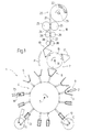
- Figure 1 shows a schematic front view, with parts removed for clarity, of a preferred embodiment of the machine according to the present invention;
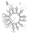
- Figure 2 shows a larger-scale schematic front view of a first detail of the Figure 1 machine;
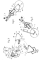
- Figure 3 shows a larger-scale schematic front view of a second detail of the Figure 1 machine;
- Figure 4 shows a larger-scale schematic front view of a third detail of the Figure 1 machine;
- Figure 5 shows a larger-scale schematic front view of a fourth detail of the Figure 1 machine.
-
-
Number 1 in Figure 1 indicates as a whole an automatic packing machine for producing packets of cigarettes (not shown), wherein agroup 2 of cigarettes is first wrapped in asheet 3 of foil wrapping material, and is then inserted inside a blank (not shown) which is folded aboutgroup 2 to form a packet of cigarettes (not shown). -
Packing machine 1 comprises awrapping wheel 4 powered to rotate continuously (clockwise in Figure 1) about acentral axis 5 perpendicular to the Figure 1 plane, and having a number ofperipheral seats 6 equally spaced aboutaxis 5. Eachseat 6 provides for receiving and conveying first arespective sheet 3 of wrapping material folded substantially into a U, and then also arespective group 2 of cigarettes, which is wrapped insheet 3 of wrapping material. -
Packing machine 1 also comprises asupply device 7 for successivelyfeeding sheets 3 of wrapping material torespective seats 6 on wrappingwheel 4 at aloading station 8; a knownloading station 9 wheregroups 2 of cigarettes are fed successively torespective seats 6 on wrappingwheel 4; two knownfolding devices 10 and 11 for folding asheet 3 of wrapping material about arespective group 2 of cigarettes atrespective folding stations unloading station 14 wheregroups 2 wrapped inrespective sheets 3 of wrapping material are extracted successively fromrespective seats 6 on wrappingwheel 4 and fed to successive known wrapping units (not shown). -
Supply device 7 comprises atransfer wheel 15 powered to rotate continuously (anticlockwise in Figure 1) about acentral axis 16 parallel toaxis 5, and having a number ofperipheral folding spindles 17 equally spaced aboutaxis 16. Eachfolding spindle 17 provides for picking up arespective sheet 3 of wrapping material from a knownsupply unit 18, at an output ofunit 18 defined by asupply station 19, and forfeeding sheet 3 of wrapping material to arespective seat 6 atloading station 8. -
Supply device 7 also comprises a folding element P located along the path offolding spindles 17 betweensupply station 19 andloading station 8. -
Supply unit 18 comprises a knownunwinding station 20 where astrip 21 of foil is unwound off areel 22 supported on apin 23; a knownembossing station 24 having twoembossing rollers 25; twofeed rollers 26 forfeeding strip 21 alongsupply unit 18; and a knowncutting station 27 having twocutting rollers 28. - As shown more clearly in Figure 3,
folding spindles 17 are connected totransfer wheel 15 via the interposition ofrespective rocker arms 29, each of which is hinged to transferwheel 15 to swing, with respect totransfer wheel 15, about anaxis 30 parallel toaxis 16. Eachrocker arm 29 comprises afirst arm 31 extending towardsaxis 16 and fitted on the free end with atappet roller 32 connected to afixed cam 33 defining, withroller 32, acontrol device 34 for controlling the angular position ofrocker arm 29 aboutrespective axis 30; and asecond arm 35 extending outwards oftransfer wheel 15 and fitted on the free end with arespective folding spindle 17. - Each
folding spindle 17 is substantially trapezoidal and is defined by alarge bottom surface 36 parallel toaxis 16, by asmall top surface 37 parallel tosurface 36 and outwards ofsurface 36 with respect toaxis 16, and by two inclinedlateral surfaces folding spindle 17, and which form, withtop surface 37, twoedges 40 parallel toaxis 16. Eachfolding spindle 17 is fixed torespective arm 35 atbottom surface 36, and comprises a known pneumatic suction device 41, which comes out through a number ofsuction holes 42 formed insurfaces respective sheet 3 of wrapping material. - Each
folding spindle 17 comprises aninner body 43 of nondeformable material, typically metal, covered atsurfaces outer layer 44 of deformable material, typically rubber or sponge. In an alternative embodiment not shown,folding spindles 17 have noouter layers 44 of deformable material. - Each
folding spindle 17 also comprises agripper 45 hinged tobottom surface 36 to retain arespective sheet 3 of wrapping material onlateral surface 38. - As shown more clearly in Figure 2, each
seat 6 is defined on arespective support 46 connected to wrappingwheel 4 via the interposition of arespective rocker arm 47 hinged to wrappingwheel 4 to swing, with respect to wrappingwheel 4, about anaxis 48 parallel toaxis 5. Eachrocker arm 47 comprises afirst arm 49 extending towardsaxis 5 and fitted on the free end with atappet roller 50 connected to afixed cam 51 defining, withroller 50, acontrol device 52 for controlling the angular position ofrocker arm 47 aboutrespective axis 48; and asecond arm 53 extending outwards ofwrapping wheel 4 and fitted on the free end with arespective support 46. - Each
seat 6 inrespective support 46 is defined by abottom wall 54 fitted torespective arm 53, and by twolateral walls 55 hinged on opposite sides ofwall 54 to swing, aboutrespective axes 56 parallel toaxis 5, between an open position and a closed position. In the open position, the twolateral walls 55 of eachseat 6 form an obtuse angle withbottom wall 54, and the section ofseat 6 is in the form of an isosceles trapezium negatively reproducing the shape offolding spindle 17. In the closed position, the twolateral walls 55 of eachseat 6 form a substantially right angle withbottom wall 54, andseat 6 has a substantially rectangular section of substantially the same dimensions as agroup 2 of cigarettes. - The angular position of
lateral walls 55 aboutrespective axes 56 is controlled by acontrol device 57 comprising twofirst arms 58, each of which has one end fitted to a respectivelateral wall 55, and the other end hinged to one end of asecond arm 59. The other end of eacharm 59 is hinged to a tubular body 60, which slides alongrespective arm 53 and comprises anappendix 61, to the free end of which is hinged atappet roller 62 connected to afixed cam 63 to control the sliding movement of body 60 alongrespective arm 53. - The inner surfaces of
walls wheel 4. - As shown more clearly in Figure 4,
folding device 10 comprises acylinder 64 rotating about afixed axis 65 parallel toaxis 5; and a pair offolding elements 66 hinged tocylinder 64, and which are swung by a known cam control device (not shown) to fold asheet 3 of wrapping material longitudinally about arespective group 2 of cigarettes. - As shown more clearly in Figure 5, folding device 11 comprises a
cylinder 67 rotating about afixed axis 68 parallel toaxis 5; and two pairs of folding elements 69 (only one shown in Figure 5) hinged tocylinder 67, and which are swung by a known cam control device (not shown) to fold both ends (only one shown in Figure 5) of asheet 3 of wrapping material about arespective group 2 of cigarettes. - Operation of
packing machine 1 will now be described with reference to onefolding spindle 17 and onecorresponding seat 6, and as of the instant in which foldingspindle 17 is brought intosupply station 19 bytransfer wheel 15 rotating aboutaxis 16. - Before being fed from
supply unit 18 to foldingspindle 17,sheet 3 of wrapping material is embossed in known manner byembossing rollers 25, and is worked by a first pair of blades (not shown) oncutting rollers 28, which form onsheet 3 said preformed tear line (not shown). - As shown more clearly in Figure 3, as
folding spindle 17 enterssupply station 19, thelateral surface 38 ofspindle 17contacts sheet 3 of wrapping material, which is retained onlateral surface 38 by the suction generated by suction device 41, which is activated before foldingspindle 17 enterssupply station 19. At the same time,gripper 45 is also activated to retainsheet 3 of wrapping material onlateral surface 38. Suction device 41 andgripper 45 perform substantially the same function, which is that of retainingsheet 3 of wrapping material onlateral surface 38. In alternative embodiments not shown,gripper 45 or suction device 41 is dispensed with. -
Sheet 3 of wrapping material, still integral withstrip 21, is drawn out ofsupply unit 18 by foldingspindle 17 rotating continuously aboutaxis 16, is wound about foldingspindle 17, and is folded substantially into an L about theedge 40 defined betweensurfaces surface 37, from which a rear portion ofsheet 3 of wrapping material projects rearwards and is substantially coplanar with the intermediate portion ofsheet 3 contactingsurface 37. - Once extracted to substantially its full length,
sheet 3 of wrapping material is detached in known manner from the rest offoil strip 21 by a second pair of blades (not shown) oncutting rollers 28, and is transferred by foldingspindle 17 toloading station 8. Betweensupply station 19 andloading station 8,sheet 3 of wrapping material is engaged by folding element P, which assists in retainingsheet 3 of wrapping material onfront edge 40 andtop surface 37. - All the way between
unloading station 14 andloading station 9. i.e. through the whole ofloading station 8,control device 57 keepsseat 6 in said open position. - On nearing
loading station 8, foldingspindle 17 andcorresponding seat 6 are swung byrespective control devices respective axes transfer wheel 15 and wrappingwheel 4 respectively; which advanced swings are continued until foldingspindle 17 is positioned substantially facingseat 6 and begins penetrating and gradually meshing withseat 6 in substantially the same way as a gear tooth. At this point, to keep foldingspindle 17 andseat 6 facing each other and complete insertion of foldingspindle 17 insideseat 6,control devices folding spindle 17 with respect to transferwheel 15 andseat 6 with respect to wrappingwheel 4. - As it is inserted inside
seat 6, foldingspindle 17 folds the rear portion ofsheet 3 about therear edge 40 and so foldssheet 3 into a U ontolateral walls 55 ofseat 6. In particular, foldingspindle 17 andseat 6 act as a punch and die respectively to effectively foldsheet 3 of wrapping material without subjectingsheet 3 to excessive mechanical stress possibly resulting in partial or total tearing of said tear-off portion (not shown) ofsheet 3. An important, though not essential, role in reducing mechanical stress onsheet 3 is played by theouter layer 44 of deformable material of foldingspindle 17. - As
top surface 37 of foldingspindle 17 substantially contactsbottom wall 54 ofseat 6, the suction throughholes 42 in foldingspindle 17 is cut off, and the suction through the holes (not shown) inseat 6 is activated so as to releasesheet 3 of wrapping material inside, and adhering pneumatically to,seat 6. - Once
sheet 3 is loaded, foldingspindle 17 disengagesseat 6, which is fed, by wrappingwheel 4 rotating continuously, from loadingstation 8 toloading station 9, whereseat 6 receives arespective group 2 of cigarettes from a known supply conveyor (not shown). - Once
group 2 is loaded,control device 57 setsseat 6 to said closed position to retain the whole formed bygroup 2 and bysheet 3 folded into a U aboutgroup 2.Seat 6 is then fed throughfolding stations folding devices 10 and 11 provide respectively for longitudinally folding and folding the ends ofsheet 3 aboutgroup 2 to form about group 2 a wrapping 70. Finally,seat 6 is fed through unloadingstation 14 where the whole defined bygroup 2 and by wrapping 70 is fed in known manner to a known follow-up wrapping unit (not shown). - The above operations are repeated cyclically.
- In an alternative embodiment not shown,
sheet 3 of wrapping material, once extracted fromsupply unit 18, is wound about foldingspindle 17 and folded substantially into a U ontolateral surfaces top surface 37 of foldingspindle 17.
Claims (23)
- A method of continuously wrapping a product, the method comprising the steps of feeding a sheet (3) of wrapping material to an output (19) of a line (18) for supplying wrapping material (21); and feeding said sheet (3), at a first loading station (8), into a seat (6) on a wrapping conveyor (4), the sheet (3) being arranged in a substantially U-folded configuration inside the respective seat (6); the method being characterized by said sheet (3) being transferred from said output (19) to said seat (6) by means of a folding spindle (17) about which the sheet (3) is folded at least partly into a U before reaching said first loading station (8); the spindle (17) releasing the U-folded sheet (3) inside the seat (6), and the seat (6) and the sheet (3) being fed through a second loading station (9) to receive said product (2).
- A method as claimed in Claim 1, characterized in that the sheet (3) is folded into a U in two successive steps, of which a first step comprises folding the sheet (3) into an L about the spindle (17) as the spindle (17) travels between said output (19) and said first loading station (8), and a second step is performed by inserting the spindle (17) inside said seat (6).
- A method as claimed in Claim 2, characterized in that the spindle (17) is inserted inside the seat (6) by causing the spindle (17) to mesh gradually with the seat (6).
- A method as claimed in any one of Claims 1 to 3, characterized in that said sheet (3) is folded about said spindle (17) by winding the sheet (3) gradually about the spindle (17).
- A method as claimed in any one of Claims 1 to 4, characterized in that said spindle (17) is carried by a rotary support (15) rotated continuously about a fixed axis (16).
- A method as claimed in any one of Claims 2 to 5, characterized in that said spindle (17) and said seat (6) are kept facing each other as the spindle (17) is inserted inside the seat (6).
- A method as claimed in Claim 5 or 6, characterized in that said spindle (17) is kept facing said seat (6) by imparting to the spindle (17) a first movement with respect to said support (15), and by simultaneously imparting to the seat (6) a second movement with respect to said wrapping conveyor (4).
- A method as claimed in Claim 7, characterized in that said first movement and said second movement are oscillations about respective axes (30, 48) movable with said support (15) and said wrapping conveyor (4) respectively.
- A method as claimed in any one of Claims 1 to 8, characterized in that said spindle (17) is substantially trapezoidal and defined by an inclined first and second lateral surface (38, 39) located respectively at the front and rear in a traveling direction of the spindle (17) past said output (19), and by an intermediate third surface (37); said sheet (3) being folded about said spindle (17) by adhering first to said first lateral surface (38) and then to said intermediate third surface (37).
- A method as claimed in any one of Claims 1 to 9, characterized in that said seat (6) is defined by a bottom wall (54) and by two lateral walls (55) movable between an open first position and a closed second position; said two lateral walls (55) being maintained in said first position during supply of said sheet (3) of wrapping material and said product (2), and being moved into said second position to hold together said sheet (3) of wrapping material and said product (2).
- A machine for continuously wrapping a product, the machine comprising a line (18) for supplying wrapping material (21) and having an output (19); a wrapping conveyor (4) having a first loading station (8) for a sheet (3) of wrapping material; and at least one seat (6) carried by the wrapping conveyor (4) and for receiving and conveying said sheet (3) of wrapping material and a respective product (2); the machine being characterized by comprising at least one folding spindle (17); and actuating means (15) for feeding the folding spindle (17) through said output (19) to pick up and fold said sheet (3) of wrapping material at least partly into a U about the folding spindle (17), and then through said first loading station (8) to release the U-folded sheet (3) inside said seat (6); the wrapping conveyor (4) having a second loading station (9) for said product (2), located downstream from said first loading station (8) in a traveling direction of said seat (6).
- A machine as claimed in Claim 11, characterized in that said folding spindle (17) is so formed as to be inserted inside said seat (6) at said first loading station (8) to fold said sheet (3) of wrapping material into a U inside said seat (6).
- A machine as claimed in Claim 12, characterized in that said folding spindle (17) is so formed as to negatively reproduce the shape of at least a portion of said seat (6).
- A machine as claimed in any one of Claims 11 to 13, characterized in that said folding spindle (17) is substantially trapezoidal and defined by an inclined first and second lateral surface (38, 39) located respectively at the front and rear in a traveling direction of the folding spindle (17) past said output, and by an intermediate third surface (37).
- A machine as claimed in Claim 14, characterized in that said folding spindle (17) comprises a gripper (45) to retain said sheet (3) of wrapping material on said first lateral surface (38).
- A machine as claimed in Claim 14 or 15, characterized in that at least said first lateral surface and said intermediate third surface (38, 37) comprise pneumatic gripping means (41).
- A machine as claimed in any one of Claims 11 to 16, characterized in that said wrapping conveyor (4) is a wrapping wheel (4) rotating about a fixed first axis (5); said actuating means comprising a powered support (15) rotating about a fixed second axis (16) parallel to the first axis (5).
- A machine as claimed in Claim 17, characterized in that first articulated connecting means (29) are interposed between said folding spindle (17) and said support (15) to guide the folding spindle (17) as the folding spindle is oscillated about a third axis (30) parallel to said second axis (16).
- A machine as claimed in Claim 18, characterized in that said first articulated connecting means (29) comprise a first arm (35), and a first hinge coaxial with said third axis (30) and connecting said first arm (35) to said support (15); first control means (34) being provided to control an angular position of the first arm (35) about the third axis (30).
- A machine as claimed in any one of Claims 17 to 19, characterized in that said wrapping wheel (4) comprises at least one head (46) in which said seat (6) is defined; second articulated connecting means (47) being provided to connect said head (46) to said wrapping wheel (4).
- A machine as claimed in Claim 20, characterized in that said second articulated connecting means (47) comprise a second arm (53), and a second hinge having a fourth axis (48), parallel to said first axis (5), and connecting said second arm (53) to said wrapping wheel (4); second control means (52) being provided to control an angular position of the second arm (53) about the fourth axis (48).
- A machine as claimed in any one of Claims 11 to 21, characterized in that said seat (6) comprises a bottom wall (54); two lateral walls (55) movable, with respect to each other, between an open first position and a closed second position; and second actuating means (57) for keeping said two lateral walls (55) in said first position during supply of said sheet (3) of wrapping material and said product (2), and for moving said two lateral walls (55) into said second position to retain the sheet (3) of wrapping material and the product (2) inside the seat (6).
- A machine as claimed in Claim 22, characterized in that each of the movable said lateral walls (55) forms with said bottom wall (54) an obtuse angle in said first position, and a substantially right angle in said second position.
Applications Claiming Priority (2)
| Application Number | Priority Date | Filing Date | Title |
|---|---|---|---|
| IT98BO000129A IT1299880B1 (en) | 1998-03-05 | 1998-03-05 | METHOD AND MACHINE FOR THE CONTINUOUS WRAPPING OF A PRODUCT. |
| ITBO980129 | 1998-03-05 |
Publications (2)
| Publication Number | Publication Date |
|---|---|
| EP0940339A1 true EP0940339A1 (en) | 1999-09-08 |
| EP0940339B1 EP0940339B1 (en) | 2004-03-03 |
Family
ID=11342979
Family Applications (1)
| Application Number | Title | Priority Date | Filing Date |
|---|---|---|---|
| EP99104385A Expired - Lifetime EP0940339B1 (en) | 1998-03-05 | 1999-03-04 | Continuous product wrapping method and machine |
Country Status (7)
| Country | Link |
|---|---|
| US (1) | US6141944A (en) |
| EP (1) | EP0940339B1 (en) |
| CN (2) | CN1174840C (en) |
| DE (1) | DE69915145T2 (en) |
| ES (1) | ES2214762T3 (en) |
| IT (1) | IT1299880B1 (en) |
| RU (1) | RU2223898C2 (en) |
Cited By (8)
| Publication number | Priority date | Publication date | Assignee | Title |
|---|---|---|---|---|
| EP1145957A1 (en) * | 2000-04-12 | 2001-10-17 | G.D Societa' Per Azioni | Method and unit for forming tubular wrappings on a cigarette packing machine |
| EP1176657A1 (en) | 2000-07-25 | 2002-01-30 | BM-Battery Machines GmbH | Device for inserting battery or accumulator plates in sleeves of separator material |
| WO2003057567A1 (en) * | 2002-01-11 | 2003-07-17 | Focke & Co. (Gmbh & Co.) | Device for producing (cigarette) packs |
| EP1533232A1 (en) * | 2003-11-21 | 2005-05-25 | G.D Societ Per Azioni | Product packing unit |
| EP1842774A1 (en) * | 2006-04-04 | 2007-10-10 | G.D Societ Per Azioni | Method and machine for packing articles |
| WO2016008559A1 (en) * | 2014-07-16 | 2016-01-21 | Focke & Co. (Gmbh & Co. Kg) | Method and device for producing packages, in particular cigarette packages |
| WO2016066989A1 (en) * | 2014-10-31 | 2016-05-06 | British American Tobacco (Investments) Limited | Apparatus and method for manufacturing a smoking article pack |
| IT201600116650A1 (en) * | 2016-11-18 | 2018-05-18 | Cmfima S R L | GROUP OF INCARNATION |
Families Citing this family (15)
| Publication number | Priority date | Publication date | Assignee | Title |
|---|---|---|---|---|
| IT1309962B1 (en) * | 1999-04-08 | 2002-02-05 | Azionaria Costruzioni Acma Spa | METHOD AND DEVICE FOR THE CONTINUOUS WRAPPING OF PRODUCTS |
| ITBO20070439A1 (en) * | 2007-06-26 | 2008-12-27 | Gd Spa | METHOD OF BENDING A SHEET OF PAPERS AROUND A GROUP OF CIGARETTES AND CORRESPONDENT PACKAGE OF CIGARETTES |
| ITBO20070492A1 (en) * | 2007-07-18 | 2007-10-17 | Gd Spa | METHOD OF BENDING A SHEET OF RECTANGULAR PAPER AROUND A PARALLELEPIPED ITEM TO FORM A TUBULAR ENTRANCE WITH AN OPEN END. |
| ITBO20080092A1 (en) * | 2008-02-13 | 2009-08-14 | Gd Spa | CIGARETTE PACKAGING MACHINE FOR THE CONSTRUCTION OF A RIGID PACKAGE WITH HINGED LID. |
| CN201296392Y (en) * | 2008-11-01 | 2009-08-26 | 魏徽 | Racking machine package receiving-clamping device |
| IT1392017B1 (en) * | 2008-12-12 | 2012-02-09 | Ima Flavour S R L Ora Ima Ind S R L | MACHINE FOR THE CONSTRUCTION OF BAGS-FILTERS IN BAGS WITH INFUSION PRODUCTS |
| IT1401804B1 (en) * | 2010-06-30 | 2013-08-28 | Azionaria Costruzioni Acma Spa | PRODUCT WRAPPING MACHINE. |
| EP2688805B1 (en) * | 2011-03-23 | 2014-12-31 | Robert Bosch GmbH | Method for packaging products, particularly portions of chocolate or the like, and facility for implementing the method |
| US9003747B2 (en) * | 2012-04-23 | 2015-04-14 | Alain Cerf | Process and apparatus for increasing stacking strength of film wrapped articles |
| PT3733383T (en) * | 2019-05-02 | 2023-03-15 | Teepack Spezialmaschinen Gmbh & Co Kg | DEVICE AND PROCESS FOR THE PRODUCTION OF A SACKET WITH A PACKAGING, CONTAINING A MATERIAL THAT CAN BE INFUSIONED |
| US11414222B2 (en) * | 2019-10-23 | 2022-08-16 | Create Technologies, Inc. | Automated system for the integration of a liner and envelope |
| EP3960427B1 (en) | 2020-08-31 | 2025-01-01 | Teepack Spezialmaschinen GmbH & Co. KG | Device for manufacturing a bag accommodated in an envelope |
| CN113753322B (en) * | 2021-10-25 | 2025-07-15 | 重庆康创智恒智能装备有限公司 | Ice cream paper packaging machine |
| CN115973509B (en) * | 2023-03-18 | 2023-05-16 | 河北威达蓝海环保科技股份有限公司 | Automatic packaging equipment for denitration catalyst before drying |
| IT202300006993A1 (en) * | 2023-04-12 | 2024-10-12 | Ima Spa | FILLING AND CLOSING GROUP OF PACKAGING AND RELATED PROCEDURE. |
Citations (5)
| Publication number | Priority date | Publication date | Assignee | Title |
|---|---|---|---|---|
| GB906379A (en) * | 1957-08-12 | 1962-09-19 | Novotechnics Ltd | Machine for packing and wrapping articles |
| GB1570605A (en) * | 1976-03-27 | 1980-07-02 | Molins Ltd | Wrapping groups of cigarettes |
| GB2138382A (en) | 1983-04-15 | 1984-10-24 | Molins Plc | Cigarette packing machines |
| US5392586A (en) | 1991-03-29 | 1995-02-28 | Japan Tobacco, Inc. | Article transferring/wrapping apparatus |
| DE19502562A1 (en) * | 1995-01-27 | 1996-08-01 | Pactec Verpackungsmaschinen Fa | Continuous system for wrapping goods in sheet material |
Family Cites Families (3)
| Publication number | Priority date | Publication date | Assignee | Title |
|---|---|---|---|---|
| DE2949252A1 (en) * | 1979-12-07 | 1981-06-11 | Focke & Co, 2810 Verden | METHOD AND DEVICE FOR PACKING CIGARETTES OR THE LIKE |
| US4607477A (en) * | 1983-04-15 | 1986-08-26 | Molins Plc | Cigarette packing machines |
| IT1285921B1 (en) * | 1996-05-06 | 1998-06-26 | Gd Spa | METHOD FOR HANDLING PRODUCTS |
-
1998
- 1998-03-05 IT IT98BO000129A patent/IT1299880B1/en active IP Right Grant
-
1999
- 1999-03-04 EP EP99104385A patent/EP0940339B1/en not_active Expired - Lifetime
- 1999-03-04 DE DE69915145T patent/DE69915145T2/en not_active Expired - Fee Related
- 1999-03-04 ES ES99104385T patent/ES2214762T3/en not_active Expired - Lifetime
- 1999-03-04 RU RU99104399/12A patent/RU2223898C2/en not_active IP Right Cessation
- 1999-03-05 CN CNB991056256A patent/CN1174840C/en not_active Expired - Fee Related
- 1999-03-05 CN CN99105979A patent/CN1121967C/en not_active Expired - Fee Related
- 1999-03-05 US US09/263,964 patent/US6141944A/en not_active Expired - Fee Related
Patent Citations (5)
| Publication number | Priority date | Publication date | Assignee | Title |
|---|---|---|---|---|
| GB906379A (en) * | 1957-08-12 | 1962-09-19 | Novotechnics Ltd | Machine for packing and wrapping articles |
| GB1570605A (en) * | 1976-03-27 | 1980-07-02 | Molins Ltd | Wrapping groups of cigarettes |
| GB2138382A (en) | 1983-04-15 | 1984-10-24 | Molins Plc | Cigarette packing machines |
| US5392586A (en) | 1991-03-29 | 1995-02-28 | Japan Tobacco, Inc. | Article transferring/wrapping apparatus |
| DE19502562A1 (en) * | 1995-01-27 | 1996-08-01 | Pactec Verpackungsmaschinen Fa | Continuous system for wrapping goods in sheet material |
Cited By (13)
| Publication number | Priority date | Publication date | Assignee | Title |
|---|---|---|---|---|
| EP1145957A1 (en) * | 2000-04-12 | 2001-10-17 | G.D Societa' Per Azioni | Method and unit for forming tubular wrappings on a cigarette packing machine |
| US6513533B2 (en) | 2000-04-12 | 2003-02-04 | G.D Societa' Per Azioni | Method for forming tubular wrappings on a cigarette packing machine |
| EP1176657A1 (en) | 2000-07-25 | 2002-01-30 | BM-Battery Machines GmbH | Device for inserting battery or accumulator plates in sleeves of separator material |
| WO2003057567A1 (en) * | 2002-01-11 | 2003-07-17 | Focke & Co. (Gmbh & Co.) | Device for producing (cigarette) packs |
| EP1533232A1 (en) * | 2003-11-21 | 2005-05-25 | G.D Societ Per Azioni | Product packing unit |
| US7127873B2 (en) | 2003-11-21 | 2006-10-31 | G.D. Societa' Per Azioni | Product packing unit |
| EP1842774A1 (en) * | 2006-04-04 | 2007-10-10 | G.D Societ Per Azioni | Method and machine for packing articles |
| US7458196B2 (en) | 2006-04-04 | 2008-12-02 | G.D Societa' Per Azioni | Method and machine for packing articles |
| WO2016008559A1 (en) * | 2014-07-16 | 2016-01-21 | Focke & Co. (Gmbh & Co. Kg) | Method and device for producing packages, in particular cigarette packages |
| WO2016066989A1 (en) * | 2014-10-31 | 2016-05-06 | British American Tobacco (Investments) Limited | Apparatus and method for manufacturing a smoking article pack |
| EP3212513A1 (en) * | 2014-10-31 | 2017-09-06 | British American Tobacco (Investments) Ltd | Apparatus and method for manufacturing a smoking article pack |
| IT201600116650A1 (en) * | 2016-11-18 | 2018-05-18 | Cmfima S R L | GROUP OF INCARNATION |
| EP3323735A1 (en) * | 2016-11-18 | 2018-05-23 | Cmfima S.R.L. | Wrapping assembly |
Also Published As
| Publication number | Publication date |
|---|---|
| CN1121967C (en) | 2003-09-24 |
| US6141944A (en) | 2000-11-07 |
| DE69915145D1 (en) | 2004-04-08 |
| ITBO980129A0 (en) | 1998-03-05 |
| CN1174840C (en) | 2004-11-10 |
| RU2223898C2 (en) | 2004-02-20 |
| EP0940339B1 (en) | 2004-03-03 |
| IT1299880B1 (en) | 2000-04-04 |
| ITBO980129A1 (en) | 1999-09-05 |
| DE69915145T2 (en) | 2005-01-05 |
| CN1229711A (en) | 1999-09-29 |
| ES2214762T3 (en) | 2004-09-16 |
| CN1234358A (en) | 1999-11-10 |
Similar Documents
| Publication | Publication Date | Title |
|---|---|---|
| EP0940339B1 (en) | Continuous product wrapping method and machine | |
| EP1035021B1 (en) | Method and device for forming a packet of cigarettes | |
| US5133173A (en) | Method and equipment for wrapping groups of packets | |
| EP1452448B1 (en) | Method of producing soft packets of cigarettes | |
| US20230084810A1 (en) | Manufacturing machine and manufacturing method for the production of a tubular element, in particular for a smoking article | |
| JPH10194219A (en) | Pocket wrapping method and its device | |
| EP1052171B1 (en) | Method and device for feeding groups of cigarettes to a continuous wrapping line of a packing machine | |
| EP1640274A2 (en) | Method and unit for applying a label to an article | |
| EP0860358A1 (en) | Product wrapping method and machine | |
| US6286291B1 (en) | Method and machine for wrapping a product | |
| EP4099853B1 (en) | Manufacturing machine and manufacturing method for the production of a tubular element provided with a filter at one end | |
| EP0936143B1 (en) | Method and machine for packing a product | |
| JPH10211903A (en) | Device for manufacturing packet out of thin wrapping material | |
| EP1640268B1 (en) | A unit for overwrapping products, in particular packets, and a relative overwrapping method | |
| US6901721B2 (en) | Unit for overwrapping packets | |
| EP0792807B1 (en) | Method and unit for folding packing blanks along preformed bend lines | |
| EP1346916A1 (en) | A method and a unit for feeding elements of sheet material to a product wrapping line | |
| EP2110319B1 (en) | A unit and a method for wrapping tobacco products | |
| EP0972706A1 (en) | Packaging machine for wrapping a product | |
| EP1467912B1 (en) | Method and machine for wrapping an article | |
| EP1772382A1 (en) | Method and unit for transferring a product on an intermittent packing machine | |
| EP1150886B1 (en) | Method and machine for wrapping articles |
Legal Events
| Date | Code | Title | Description |
|---|---|---|---|
| PUAI | Public reference made under article 153(3) epc to a published international application that has entered the european phase |
Free format text: ORIGINAL CODE: 0009012 |
|
| AK | Designated contracting states |
Kind code of ref document: A1 Designated state(s): DE ES FR GB IT |
|
| AX | Request for extension of the european patent |
Free format text: AL;LT;LV;MK;RO;SI |
|
| 17P | Request for examination filed |
Effective date: 20000307 |
|
| AKX | Designation fees paid |
Free format text: DE ES FR GB IT |
|
| RAP1 | Party data changed (applicant data changed or rights of an application transferred) |
Owner name: G.D SOCIETA' PER AZIONI |
|
| GRAP | Despatch of communication of intention to grant a patent |
Free format text: ORIGINAL CODE: EPIDOSNIGR1 |
|
| GRAS | Grant fee paid |
Free format text: ORIGINAL CODE: EPIDOSNIGR3 |
|
| GRAA | (expected) grant |
Free format text: ORIGINAL CODE: 0009210 |
|
| AK | Designated contracting states |
Kind code of ref document: B1 Designated state(s): DE ES FR GB IT |
|
| REG | Reference to a national code |
Ref country code: GB Ref legal event code: FG4D |
|
| PGFP | Annual fee paid to national office [announced via postgrant information from national office to epo] |
Ref country code: GB Payment date: 20040317 Year of fee payment: 6 |
|
| PGFP | Annual fee paid to national office [announced via postgrant information from national office to epo] |
Ref country code: FR Payment date: 20040318 Year of fee payment: 6 |
|
| PGFP | Annual fee paid to national office [announced via postgrant information from national office to epo] |
Ref country code: ES Payment date: 20040407 Year of fee payment: 6 |
|
| REF | Corresponds to: |
Ref document number: 69915145 Country of ref document: DE Date of ref document: 20040408 Kind code of ref document: P |
|
| PGFP | Annual fee paid to national office [announced via postgrant information from national office to epo] |
Ref country code: DE Payment date: 20040430 Year of fee payment: 6 |
|
| REG | Reference to a national code |
Ref country code: ES Ref legal event code: FG2A Ref document number: 2214762 Country of ref document: ES Kind code of ref document: T3 |
|
| ET | Fr: translation filed | ||
| PLBE | No opposition filed within time limit |
Free format text: ORIGINAL CODE: 0009261 |
|
| STAA | Information on the status of an ep patent application or granted ep patent |
Free format text: STATUS: NO OPPOSITION FILED WITHIN TIME LIMIT |
|
| 26N | No opposition filed |
Effective date: 20041206 |
|
| PG25 | Lapsed in a contracting state [announced via postgrant information from national office to epo] |
Ref country code: IT Free format text: LAPSE BECAUSE OF NON-PAYMENT OF DUE FEES;WARNING: LAPSES OF ITALIAN PATENTS WITH EFFECTIVE DATE BEFORE 2007 MAY HAVE OCCURRED AT ANY TIME BEFORE 2007. THE CORRECT EFFECTIVE DATE MAY BE DIFFERENT FROM THE ONE RECORDED. Effective date: 20050304 Ref country code: GB Free format text: LAPSE BECAUSE OF NON-PAYMENT OF DUE FEES Effective date: 20050304 |
|
| PG25 | Lapsed in a contracting state [announced via postgrant information from national office to epo] |
Ref country code: ES Free format text: LAPSE BECAUSE OF NON-PAYMENT OF DUE FEES Effective date: 20050305 |
|
| PG25 | Lapsed in a contracting state [announced via postgrant information from national office to epo] |
Ref country code: DE Free format text: LAPSE BECAUSE OF NON-PAYMENT OF DUE FEES Effective date: 20051001 |
|
| GBPC | Gb: european patent ceased through non-payment of renewal fee |
Effective date: 20050304 |
|
| PG25 | Lapsed in a contracting state [announced via postgrant information from national office to epo] |
Ref country code: FR Free format text: LAPSE BECAUSE OF NON-PAYMENT OF DUE FEES Effective date: 20051130 |
|
| REG | Reference to a national code |
Ref country code: FR Ref legal event code: ST Effective date: 20051130 |
|
| REG | Reference to a national code |
Ref country code: ES Ref legal event code: FD2A Effective date: 20050305 |