EP0941662B1 - Procédé et dispositif de séparation de saucisses - Google Patents
Procédé et dispositif de séparation de saucisses Download PDFInfo
- Publication number
- EP0941662B1 EP0941662B1 EP99103384A EP99103384A EP0941662B1 EP 0941662 B1 EP0941662 B1 EP 0941662B1 EP 99103384 A EP99103384 A EP 99103384A EP 99103384 A EP99103384 A EP 99103384A EP 0941662 B1 EP0941662 B1 EP 0941662B1
- Authority
- EP
- European Patent Office
- Prior art keywords
- separator
- elements
- separating device
- sausage
- separating
- Prior art date
- Legal status (The legal status is an assumption and is not a legal conclusion. Google has not performed a legal analysis and makes no representation as to the accuracy of the status listed.)
- Expired - Lifetime
Links
Images


Classifications
-
- A—HUMAN NECESSITIES
- A22—BUTCHERING; MEAT TREATMENT; PROCESSING POULTRY OR FISH
- A22C—PROCESSING MEAT, POULTRY, OR FISH
- A22C11/00—Sausage making ; Apparatus for handling or conveying sausage products during manufacture
- A22C11/006—Separating linked sausages
Definitions
- the invention relates to a separating device for separating sausages at compartment locations according to the preamble of claim 1 and a method for dividing Sausage strands according to the preamble of claim 22.
- a generic device is e.g. known from EP 0440 039 B1. These Sausage filling machine described presses sausage meat through a filling pipe in a tubular sausage casing. Through a calibration mechanism, individual Sausage portions formed between which there are twist-off or compartment locations. The Sausage strand formed in this way is supported by two conveyor belts. length unit moves forward. In the course of this forward movement, the sausage strand passes one Separating device that defines the sausage skein into individual sausages or in groups Separate the number of sausages at the compartment locations.
- devices are rotating separating elements on both sides of the sausage strand provided that run in opposite directions on circular paths and blades at the outer end or corresponding counterholders. The separators are stored that the blades or counterhold interact at one point in their rotation, that the sausage strand is cut at a compartment.
- the transport speed of the sausage skein and the speed of rotation of the separating elements are synchronized or adapted to the product.
- the object of the present invention is to provide an improved separation device and a method with which a safe Separation of sausages, especially natural casing sausages, regardless of the location the turning points is possible.
- the conveyor belts that make up the sausage strand lead to a separator during the cutting process at a distance pulled apart, which is larger than the sausage caliber.
- the device has devices which are in the area of the compartment locations during the Engagement of the two separating elements create a distance between the conveyor belts, which is larger than the sausage caliber.
- the separating elements can e.g. from the sides between the conveyor belts against the Compartment section are pushed and cut through.
- a particularly safe and advantageous embodiment provides, however, that the separating elements on circular paths around an axis that is perpendicular to the direction of transport of the sausage strand, circulate in opposite directions. This makes a particularly gentle separation possible Risk of injury to the intestinal material is reduced.
- the conveyor belts can e.g. be pulled apart with the help of a link device or a rail.
- first and second spacer elements are provided for this purpose, which revolve with one of the two separating elements, one of the two spacer elements when the first and the second separating element engage, a first conveyor belt keep away from the sausage skein and the other spacer when the first with the second separating element, a second conveyor belt from the sausage skein keep away so that when the two separating elements engage, the distance between the conveyor belts is larger than the caliber of the sausage skein.
- both spacer elements can be put together circulate with one of the two separating elements on a common axis.
- This enables a particularly compact structure and simple manufacture, since only the one rotating cutting head is equipped with appropriate spacing elements must become.
- the one spacing element can also separate the one separating element are assigned and the other spacing element to the other separating element. Such an arrangement ensures uniform loading of the axes of rotation.
- a particularly advantageous embodiment additionally has at least a third and a fourth separating element, the third separating element together with the rotates first separating element on an axis and the fourth separating element together rotates with the second separating element on an axis.
- the third and fourth separators work together in the same way as the first and the second Separation element to separate compartment locations.
- serve third and fourth spacer elements which are analogous to the mode of action the first and second spacer elements pull the conveyor belts apart, when the third and fourth separators come into engagement.
- Several separating and spacing elements, each rotating together on one axis means one uniform loading of the respective axes.
- the circumferential spacer elements have one in the circumferential direction leading bevelled edge on between the respective conveyor belt and kicking the sausage skein to remove the conveyor belt from the sausage skein. With such a slope, the conveyor belt is removed from the sausage strand in a safe manner without damaging the conveyor belt or the Sausage strand is to be feared.
- a molded element can be placed in front of at least one of the two all-round dividing elements that work together to form two sausages on the Run ahead of the circular path.
- Such a leading centering element also engages the area in which the conveyor belts are pulled apart by the spacer elements are between the conveyor belts. In this way an unimpeded run is the Centering elements possible.
- shaped elements can be used for centering that are larger than the caliber of a sausage.
- the spacer elements can have a centering bevel, which with the sausage strand comes into contact when the respective spacer between the Sausage strand and the conveyor belt kicks.
- Such a centering slope leads to a pre-centering the compartment, which is fed to the separating elements even more safely.
- the shaped elements can also be designed such that during the intervention The sausages to be separated are separated by a sufficient distance from two separating elements exhibit. This is an advantage when processing material with sufficient Extension of the compartment between two sausages is not possible.
- Will the form elements e.g. made of V-shaped surfaces that extend transversely to the sausage strand formed, so there is at least the distance between the two sausages Separating element and the form element leading it.
- additional Form elements that e.g. run after the other separating element, the one for the division the sausage strand interacts with the first separating element can also be a larger distance can be obtained.
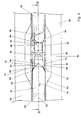
- FIG. 1 The overall view of a sausage filling machine in FIG. 1 shows a main part of the filling machine 30 with a hopper 28 for the sausage meat.
- 20 denotes a filling pipe, through the sausage meat with the help of one arranged in the machine main part 30 Vane pump is ejected in a known manner in direction 22.
- 16 denotes a brake ring gear, as it e.g. from European patent 0232 812 is known, which serves to brake the sausage casing.
- 18 denotes an in itself Known calibration gear for the formation of calibration points between the individual Sausages.
- Figure 12 shows individual sausages that are located at the compartment locations, i.e. the twist-off points with each other are connected.
- separating heads 4a, b designate separating heads of a separating device, of which only one separating head here 4a is visible.
- a motor e.g. a highly dynamic speed controllable Motor, which the revolving separating heads 4a, which are on both sides of the sausage strand are driving.
- the separating heads 4a and 4b are from the common Motor 2 driven via a gear that is of no further interest here.
- two separate motors can be used for the separating elements.
- the sausage skein or sausages are made up of two endless belts 6a, b in the direction 24, which are driven by deflection rollers 7. The totality the endless belts with their drive and the separating device is used as a length device Designated 14.
- a controller 25 is used to precisely coordinate the movements of the endless belts 6a, 6b of the discharge of the filling material through the filling pipe 20, of the calibration gear 18 and the motor 2 of the separator.
- Figure 2 shows the compartment 48 between two sausages 10 to be separated, the opposite the central axis 52 of the sausages is decentered. 82 denotes the caliber of the sausages.
- endless belts 6a and b are shown as examples, which have additional ribs are equipped to reduce the slip between the endless belt and the sausage skein.
- the endless belts 6a, 6b can e.g. be flexible straps attached to guides or Run brackets 50, 54 along. These brackets 50, 54 have in the cutting area Recesses 56, 58.
- 83 the distance between the endless belts 6a and 6b in Designated cutting area, 84 shows an example of the distance between two sausages 10 during the separation process. This distance corresponds at least to the distance a shaped element 36 from the separating elements currently in engagement.
- the separating head 4a can be seen between the two sausages in the view in FIG. He includes two lower spacers 62 and 60 and two upper spacers 68 and 66. Between these are separators 41 and 40 (that in perspective 3 can not be seen) and plate-shaped elements 36. The exact The structure of the spacer elements 60, 62, 66, 68 is detailed with reference to FIGS. 5 to 9 explained.
- Figure 4 shows the same perspective as Figure 3, only at a time just before one Compartment point 48 enters the cutting area. In this perspective, the V-shaped ones Cutouts 38 of the shaped elements 36 can be seen. In contrast to Figure 3 at the time shown in Figure 4, the spacers do not between the conveyor belts 6a, b.
- FIG. 5 shows a plan view of a sectional plane that corresponds to plane D of FIG. 3 equivalent.
- the viewing direction of FIG. 3 is designated E in FIG. Figure 5 shows accordingly the lower area of a separating device according to the invention during the engagement of two separators. For the sake of clarity, it is Sausage skein not shown.
- the separating head 4a rotates in the direction 47 around the Axis 45.
- Each spacer element 60, 62 has a centering bevel 64, which with the leading of the two sausages to be separated and for pre-centering the compartment 48 serves.
- 36 denotes shaped elements in the embodiment shown are formed from flat elements which are essentially parallel to one another extend a line that perpendicularly intersects axis 45.
- the V-shaped design the shaped elements 36 can be seen in FIG. 4.
- the V-shaped areas 38 of the Shaped elements 36 can be adjustable or formed in one piece.
- the separating head 4a carries two opposing counterholders 40, 41 which are elastically mounted.
- the Counterholder 40 is engaged with one of the two blades 42, 43 of the second separating head 4b.
- the second separating head 4b rotates about an axis 44 in the direction 46.
- On each a concave surface 49 can be provided on the leading side of the separating head 4b, that comes into contact with the leading sausage and thus an injury to the sausage casing avoids.
- both separating heads can 4a, b be equipped with blades which engage in the cutting area.
- FIG. 6 is a perspective corresponding to FIG. 5 at a point in time that the Figure 4 corresponds to shown, i.e. shortly before two sausages 10 are separated from one another should. As in FIG. 5, the sausage skein is for the sake of clarity Not shown.
- FIG. 6 shows a sectional view corresponding to plane D of FIG. 4. Accordingly, Figure 6 shows only the lower area of the invention Separator.
- the perspective in FIG. 4 is designated E in FIG.
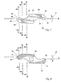
- the spacer elements 60, 62 are shown in detail in FIG. 7, the perspective corresponds to FIG. 5 or FIG. 6. 80 denotes the rounded corners, the radial protrude beyond the shaped elements 36.
- the centering slope 64 is in the Figure 7 embodiment shown in contrast to that shown in Figure 5 or Figure 6 Embodiment from an oblique area, which is shown hatched and a in flat area 65 oriented substantially perpendicular to axis 45.
- FIG. 8 shows the same spacer element rotated by 180 ° about the axis X of FIG. 7. In the forward direction, the bevels 72 are shown, which with the conveyor belt 6a in Get in touch.
- FIG. 9 shows the areas that arise when the spacing element 62, as can be seen in Figure 8, cut along the plane A and in this perspective is looked at.
- Figures 9b and c correspond to the cut surfaces B and C of Figure 8.
- FIGS. 5 to 9 each show the lower spacer elements 60, 62.
- the upper ones Spacer elements 66, 68 (see FIGS. 3, 4) have a mirror-inverted, but otherwise analog structure on.
- the centering bevels 64 correspond to the upper spacer elements the centering bevels 70 and the leading bevels 72 of the lower spacers 60, 62 correspond to the upper spacer elements 66, 68 leading slopes 74.
- All spacer elements 60 are located in the two shown embodiments, 62, 66, 68 on the first separating head 4a.
- the spacers can also on the Separating heads 4a and 4b can be divided.
- the top spacers on the first separating head 4a while the lower spacer elements are located are located on the second separating head 4b. It is also conceivable that on each cutting head only an upper and a lower spacer arranged one above the other are that when two separating elements engage, only the spacing elements one Separating head between the conveyor belts 6a, 6b.
- top and bottom in this description refer to the Perspective of Figures 1, 3 and 4 and are not to be interpreted as limiting.
- the figures 44, 45 are oriented vertically.
- the method according to the invention runs with the shown embodiment of the invention Device as follows. Sausage meat is through the funnel 28 in the Filling machine main part 30 introduced.
- the vane pump not shown, presses the sausage meat through the filling tube 20 in the direction 22. This is known in itself Filled a sausage casing applied to the filling tube and at the same time by deducted from the fill tube 20.
- the casing material filled with sausage meat is used by the Endless belts 6a, b of the length device 14 detected by the pulleys 7 in Direction 24 are driven. After a portion of sausage meat has been ejected, that of a sausage corresponds, the filling material output is stopped synchronously with the endless belts 6a, b or reduced in speed.
- the filled part of the peeled shell material is held by the endless belts 6a, b, while the calibration gear 18 holds the filling pipe 20 together with the still unfilled part of the envelope material that is on the filling pipe is rotated.
- Brake ring gear 16 is provided.
- the timing of the movement of the vane pump in the machine body 30, the calibration gear 18, the brake ring gear 16 and the endless belts 16a, b is carried out by the controller 25, the corresponding electrical signals in a manner not of interest to the individual components.
- the portions of the sausage skein turned into individual sausages are made by the endless belts 6a, b are guided past the separating device, the separating heads 4a, b engage laterally between the endless belts 6a, b, as is shown in FIG. 3 and FIG Figure 5 can be seen.
- the motor 2 of the separating device which the two separating heads 4a and 4b drives, is also from the controller 25 to a corresponding synchronous Movement driven.
- the phase positions of the individual movements are made Parameters such as the desired portion quantity, the filling speed, the caliber or the desired number of sausages that together form a sausage chain should be calculated and specified by the controller 25.
- the separating heads 4a, 4b divide the sausage strand at the compartment locations 48, so that individual Sausages 8 arise, which are conveyed on by the endless belts 6a, b until they fall or processed at the end of the length device 14 into a storage container become.
- the separating heads 4a, 4b can run at a uniform speed circulate. Depending on the speed of the sausage skein and the distance between the compartments 48, however, it may be necessary for the controller 25 to operate during a revolution a cutting head 4a, 4b changes its angular velocity.
- the speed of rotation of the separating heads 4a, 4b accordingly be adapted to the speed of the sausage skein, while in the Period during which no separating element is in contact with the sausage skein, the Rotation speed is set slower in order to be able to divide longer sausages.
- the centering bevels 64 and 70 of the spacer elements 60, 62 and 66, 68 ensure a secure insertion of the compartment 48 into the V-shaped areas 38 of the shaped elements 36, the side view of which can be seen in FIG. 3. Since the conveyor belts 6a, 6b can be spread apart by the spacer elements in this way also compartment points 48 are detected, which are very strongly decentered.
- the V-shaped opening area 38 of the centering elements 36 can be opened further than it corresponds to caliber 82 of sausages. Even if this is not the case, it will through the centering bevels 64, 70 a detection of highly decentered compartment locations 48 secured.
- the minimum distance is between the two sausages to be separated by the distance between the shaped element 36, which leads the counter-holder 40, and the ones in engagement Separating elements 40, 42 determined.
- further form elements are provided, one of which runs after the counter-holder 40, so determines the distance of a leading form element from a trailing one Form element the minimum distance of the sausages during the separation.
- the Separating head 4b in the position of FIG. 5.
- the center point is the compartment location 48 centered at least to such an extent that it is separated from the blade 42 or the counter-holder 40 can be detected.
- the blade 42 cuts the compartment 48 against the counter-holder 40, which is elastically supported by.
- the elastic bearing allows springing back the counter-holder 40, 41, so that a smooth course of the cutting process is guaranteed.
- the centering slope 64 is ensured that the spacers during Engagement does not hinder the movement of the blades 42, 43 of the cutting head 4b.
- the separated sausage is conveyed on by the conveyor belts 6a, 6b.
- the separating heads 4a, 4b continue to rotate so that the conveyor belts 6a, 6b no longer spread apart are when the separating heads 4a, 4b are in the position of FIG. 6 and FIG Figure 4 are. In this way there is a slip between those to be transported Sausages and the endless belts 6a, 6b prevented.
- the device according to the invention and the method according to the invention enable by pulling apart the conveyor belts 6a, 6b a safe detection of decentred Compartmental points 48. This allows the conveyor belts to be pulled apart Separating elements of sufficient width or centering elements that are sufficiently large Capture the area across the sausage skein.
- the device according to the invention ensures that the conveyor belts 6a, 6b the movement of the separating heads 4a, 4b do not hinder.
Landscapes
- Life Sciences & Earth Sciences (AREA)
- Engineering & Computer Science (AREA)
- Wood Science & Technology (AREA)
- Zoology (AREA)
- Food Science & Technology (AREA)
- Processing Of Meat And Fish (AREA)
- Control And Other Processes For Unpacking Of Materials (AREA)
- Meat, Egg Or Seafood Products (AREA)
Claims (24)
- Dispositif de séparation pour séparer des saucisses (10) en des points de séparation, qui sont formés entre les différentes saucisses d'un chapelet de saucisses, comportant
au moins deux bandes transporteuses (6a, 6b) se déplaçant dans la même direction, qui reçoivent entre elles les saucisses et les transportent,
au moins un premier élément séparateur (40), qui est disposé sur un premier côté du chapelet de saucisses et au moins un second élément séparateur (42), qui est disposé sur le second côté du chapelet de saucisses, les éléments séparateurs étant entraínés de manière telle qu'ils coopèrent pour séparer le chapelet de saucisses en des points de séparation,
caractérisé par
des dispositifs (60, 66) pour générer un écartement (83) entre les bandes transporteuses (6a, 6b) dans la zone de chaque point de séparation (48) à séparer, pendant la venue en prise des deux éléments séparateurs (40, 42), qui est plus grand que le calibre des saucisses (82). - Dispositif de séparation selon la revendication 1, caractérisé en ce que tournent en sens contraire le(s) premier(s) élément(s) séparateur(s) (40) sur une trajectoire circulaire autour d'un premier axe (45) et le(s) second(s) élément(s) séparateur(s) (42) sur une trajectoire circulaire autour d'un second axe (44), les deux axes (44, 45) étant perpendiculaires à la direction du sens de transport (24) du chapelet de saucisses (10, 12).
- Dispositif de séparation selon la revendication 2, caractérisé en ce que les dispositifs générant l'écartement comportent un premier élément écarteur (60) tournant avec l'un des deux éléments séparateurs (40, 42) et un second élément écarteur (66) tournant avec l'un des deux éléments séparateurs (40, 42), l'un des deux éléments écarteurs (60, 66) maintenant une première bande transporteuse (6a) à distance du chapelet de saucisses (10, 12) lors de la venue en prise du premier élément séparateur avec le second et l'autre élément écarteur (66, 60) maintenant à distance du chapelet de saucisses (10, 12) une seconde bande transporteuse (6b) lors de la venue en prise du premier élément de séparation avec le second.
- Dispositif de séparation selon la revendication 3, caractérisé en ce que le premier et le second élément d'écartement (60, 66) tournent ensemble avec le premier élément séparateur (40) autour d'un axe commun (45).
- Dispositif de séparation selon la revendication 3, caractérisé en ce que le premier et le second élément d'écartement tournent ensemble avec le second élément séparateur (42) autour d'un axe commun (44).
- Dispositif de séparation selon la revendication 3, caractérisé en ce que l'un des éléments écarteurs tourne sur un axe commun (45) avec le premier élément séparateur (40) et l'un des éléments écarteurs tourne sur un axe commun (44) avec le second élément séparateur.
- Dispositif de séparation selon l'une des revendications 3 à 6, caractérisé parl'un des troisième et quatrième éléments écarteurs (68) maintenant à distance une première bande transporteuse (6a) du chapelet de saucisses (10, 12) lors de la venue en prise du troisième (41) avec le quatrième élément séparateur (43), et l'autre des troisième et quatrième éléments écarteurs maintenant une seconde bande transporteuse (6b) à distance du chapelet de saucisses (10, 12) lors de la venue en prise du troisième (41) avec le quatrième élément séparateur (43).au moins un troisième élément séparateur (41), qui tourne avec le premier élément séparateur (40) sur le premier axe (45),au moins un quatrième élément séparateur (43), qui tourne ensemble avec le second élément séparateur (42) sur le second axe (44) de l'autre côté du chapelet de saucisses (10, 12), le troisième et le quatrième élément séparateur (41, 43) coopérant lors de la rotation de manière telle que le chapelet de saucisses (10, 12) est séparé aux points de séparation (48),au moins un troisième élément écarteur (62) qui tourne soit avec le troisième soit avec le quatrième élément séparateur,au moins un quatrième élément écarteur (68), qui tourne soit avec le troisième soit avec le quatrième élément séparateur,
- Dispositif de séparation selon la revendication 7, caractérisé en ce que le troisième et le quatrième élément écarteur (62, 68) tournent ensemble avec le troisième élément séparateur (41) sur un axe commun (45).
- Dispositif de séparation selon la revendication 7, caractérisé en ce que le troisième et le quatrième élément écarteur tournent ensemble avec le quatrième élément séparateur (43) sur un axe commun (44).
- Dispositif de séparation selon la revendication 7, caractérisé en ce que l'un des troisième et quatrième éléments écarteurs tourne ensemble avec le troisième élément séparateur (41) sur un axe commun (45) et l'autre des troisième et quatrième éléments écarteurs tourne ensemble avec le quatrième élément séparateur (43) sur un axe commun (44).
- Dispositif de séparation selon l'une des revendications 7 à 10, caractérisé en ce que précisément deux éléments séparateurs (42, 43 ; 40, 41) sont prévus par axe (44 ; 45) qui s'étendent en s'écartant l'une de l'autre de l'axe (44 ; 45) considéré sensiblement en direction opposée.
- Dispositif de séparation selon l'une des revendications 3 à 11, caractérisé en ce que les éléments écarteurs (60, 62, 66, 68) présentent une arête biseautée (72, 74) saillant dans le sens de rotation (46, 47), qui tourne lors de la rotation entre la bande transporteuse (6a, 6b) considérée à maintenir à distance et le chapelet de saucisses (10, 12), la rampe (72, 74) venant en contact avec la bande transporteuse (6a, 6b) de manière telle, que la bande transporteuse est écartée du chapelet de saucisses.
- Dispositif de séparation selon l'une des revendications 3 à 12, caractérisé en ce que les éléments écarteurs (60, 62, 66, 68) s'écartent plus loin de l'axe considéré que les éléments séparateurs considérés.
- Dispositif de séparation selon l'une des revendications 3 à 13, caractérisé en ce que les extrémités (80) éloignées des axes des éléments écarteurs (60, 62, 66, 68) sont arrondies.
- Dispositif de séparation selon l'une des revendications 3 à 14, caractérisé en ce que les éléments écarteurs (60, 62, 66, 68) comportent sur le côté orienté vers l'élément séparateur (40, 41, 42, 43) considéré une rampe de centrage (64, 70), pour amener le point de séparation (48) à l'élément séparateur considéré.
- Dispositif de séparation selon l'une des revendications 2 à 15, caractérisé en ce que chaque fois au moins l'un des deux éléments séparateurs, qui coopèrent pour séparer deux saucisses (10) est précédé par un élément formé (36) sur la trajectoire circulaire, qui centre le point de séparation (48) entre les deux saucisses à séparer (10) avant la séparation.
- Dispositif de séparation selon la revendication 16, caractérisé en ce que le ou les éléments formés (36) comprennent une zone de centrage (38) s'ouvrant dans la direction du chapelet de saucisses (10, 12) à son extrémité éloignée de l'axe.
- Dispositif de séparation selon la revendication 17, caractérisé en ce que le ou les zones de centrage en V (38) comportent chacune une zone d'ouverture, qui est au moins aussi grande que le calibre (82) du chapelet de saucisses (10, 12).
- Dispositif de séparation selon l'une des revendications 16 à 18, caractérisé en ce que le ou les éléments formés (36) sont conformés de manière telle, que les saucisses (10) considérées à séparer présentent un certain écartement pendant la venue en prise de deux éléments séparateurs.
- Dispositif de séparation selon l'une des revendications 1 à 19, caractérisé en ce que dans leur dimension les éléments séparateurs (40, 41, 42, 43) s'étendent perpendiculairement au chapelet de saucisses (10, 12) sur une largeur qui correspond au moins au calibre (82) du chapelet de saucisses (10, 12).
- Dispositif de séparation selon l'une des revendications 1 à 20, caractérisé en ce que l'un (42, 43) de deux éléments séparateurs, qui coopèrent pour séparer deux saucisses (10), comporte une lame et l'autre (40, 41) de ces deux éléments séparateurs, comporte un contre-support ou une autre lame.
- Procédé pour séparer des chapelets de saucisses en des points de séparation en saucisses distinctes ou chaínes de saucisses d'un nombre identique de saucisses, le chapelet de saucisses étant amené avec des bandes transporteuses (6a, 6b) à un dispositif de séparation et étant coupé en des points de séparation, caractérisé en ce que les bandes transporteuses (6a, 6b) sont écartées pendant l'opération de coupe dans la zone des points de séparation à séparer (48) à une distance (83) plus grande que le calibre de saucisse (82).
- Procédé selon la revendication 22, caractérisé en ce que le point de séparation (48) est centré simultanément à l'écartement des bandes transporteuses (6a, 6b).
- Procédé selon l'une des revendications 21 et 23, caractérisé en ce que pendant l'écartement des bandes transporteuses (6a, 6b) un écartement défini est créé entre les saucisses à séparer (10), avant que soit coupé le point de séparation (48).
Applications Claiming Priority (2)
| Application Number | Priority Date | Filing Date | Title |
|---|---|---|---|
| DE19810046 | 1998-03-09 | ||
| DE19810046A DE19810046C1 (de) | 1998-03-09 | 1998-03-09 | Vorrichtung und Verfahren zum Trennen von Würsten |
Publications (3)
| Publication Number | Publication Date |
|---|---|
| EP0941662A2 EP0941662A2 (fr) | 1999-09-15 |
| EP0941662A3 EP0941662A3 (fr) | 2000-07-26 |
| EP0941662B1 true EP0941662B1 (fr) | 2002-07-03 |
Family
ID=7860215
Family Applications (1)
| Application Number | Title | Priority Date | Filing Date |
|---|---|---|---|
| EP99103384A Expired - Lifetime EP0941662B1 (fr) | 1998-03-09 | 1999-02-22 | Procédé et dispositif de séparation de saucisses |
Country Status (7)
| Country | Link |
|---|---|
| US (1) | US6080054A (fr) |
| EP (1) | EP0941662B1 (fr) |
| JP (1) | JP3210907B2 (fr) |
| CN (1) | CN1086553C (fr) |
| AT (1) | ATE219887T1 (fr) |
| DE (2) | DE19810046C1 (fr) |
| ES (1) | ES2179561T3 (fr) |
Cited By (1)
| Publication number | Priority date | Publication date | Assignee | Title |
|---|---|---|---|---|
| EP4088581A1 (fr) * | 2021-05-12 | 2022-11-16 | VEMAG Maschinenbau GmbH | Dispositif de séparation permettant de séparer des portions des enveloppes oblongues remplies de masse alimentaire, ainsi que procédé correspondant |
Families Citing this family (20)
| Publication number | Priority date | Publication date | Assignee | Title |
|---|---|---|---|---|
| DE10008672C2 (de) * | 2000-02-24 | 2002-11-21 | Handtmann Albert Maschf | Füllvorrichtung zum Befüllen von Därmen |
| DE10013036A1 (de) * | 2000-03-17 | 2001-09-27 | Vemag Maschinenbau Gmbh | Verfahren und Vorrichtung zum Fördern und Vereinzeln von Würstchen oder dgl. |
| DE10055310C2 (de) * | 2000-11-08 | 2003-07-31 | Handtmann Albert Maschf | Vorrichtung und Verfahren zur Wurstherstellung und Längeneinheit zur Verwendung für eine Vorrichtung zur Wurstherstellung |
| ATE352207T1 (de) * | 2001-11-19 | 2007-02-15 | Handtmann Albert Maschf | Längeneinheit mit clipmodul |
| DE10237909B4 (de) * | 2002-08-14 | 2007-08-16 | Stimpfl & Gieseler Gmbh | Vorrichtung zum Durchtrennen der Verbindung zwischen zwei Würsten |
| ATE320190T1 (de) * | 2002-11-22 | 2006-04-15 | Handtmann Albert Maschf | Vorrichtung mit vakuumfüller und clipmodul |
| NL1025005C2 (nl) * | 2003-12-12 | 2005-06-14 | Townsend Engineering B V | Werkwijze voor het gefaseerd separeren van een worststreng, separatie-element en samenstel van separatie-elementen. |
| ES2299788T3 (es) * | 2004-12-14 | 2008-06-01 | ALBERT HANDTMANN MASCHINENFABRIK GMBH & CO. KG | Dispositivo de conformado y procedimiento de conformado para formar cabezas de extremos de embutidos. |
| ATE537703T1 (de) * | 2009-01-28 | 2012-01-15 | Handtmann Albert Maschf | Vorrichtung und verfahren zum hüllenschonenden abteilen von gefüllten wurststrängen |
| DE102009011555A1 (de) * | 2009-03-06 | 2010-09-09 | Inotec Gmbh Maschinenentwicklung Und Vertrieb | Vorrichtung zum Trennen von Wurstketten |
| JP5355186B2 (ja) * | 2009-04-02 | 2013-11-27 | プリマハム株式会社 | 紐状繋ぎ部を有する連鎖状食品の紐状繋ぎ部除去装置 |
| DE102009033725A1 (de) * | 2009-07-17 | 2011-03-24 | Vemag Maschinenbau Gmbh | Verfahren und Vorrichtung zum Herstellen von Würstchen |
| DE102010002827A1 (de) * | 2010-03-12 | 2011-09-15 | Albert Handtmann Maschinenfabrik Gmbh & Co. Kg | Vorrichtung und Verfahren zum Trennen von Wurstketten |
| CN102802424A (zh) * | 2011-03-08 | 2012-11-28 | 株式会社共荣工设 | 连锁状香肠的连接部切断装置及香肠制造系统 |
| US8641484B1 (en) * | 2013-02-15 | 2014-02-04 | Marel Meat Processing Inc. | Variable speed linker |
| DE102017120101B4 (de) * | 2017-08-31 | 2019-08-29 | Vemag Maschinenbau Gmbh | Vorrichtung zum Abteilen von schlauchförmigen Hüllen |
| DE102017120108B3 (de) * | 2017-08-31 | 2018-08-16 | Vemag Maschinenbau Gmbh | Vorrichtung zum Füllen schlauchförmiger Hüllen |
| DE102021112513B3 (de) * | 2021-05-12 | 2022-06-23 | Vemag Maschinenbau Gmbh | Portioniervorrichtung - und Verfahren sowie Crimpelement |
| DE102021124801B3 (de) | 2021-09-24 | 2023-03-16 | Vemag Maschinenbau Gmbh | Vorrichtung und Verfahren zum Transportieren und Ausschleusen von getrennten Lebensmittelportionen |
| CN114009707A (zh) * | 2021-10-20 | 2022-02-08 | 上海唐人神肉制品有限公司 | 一种德式香肠的制作方法 |
Family Cites Families (10)
| Publication number | Priority date | Publication date | Assignee | Title |
|---|---|---|---|---|
| DE2302297C2 (de) * | 1973-01-18 | 1983-08-04 | Karl 7065 Winterbach Schnell | Vorrichtung zum Einfüllen teigiger Medien in einen Darm oder dergleichen |
| US4104763A (en) * | 1976-12-06 | 1978-08-08 | Totai Company Limited | Apparatus for cutting a string of sausage links |
| US4214492A (en) * | 1978-12-26 | 1980-07-29 | Hoffman Thomas M | Method and apparatus for cutting clips off of the ends of sausages and the like |
| US4366600A (en) * | 1980-05-29 | 1983-01-04 | Townsend Engineering Company | Method and means of cutting links of encased material |
| DE3104099A1 (de) * | 1981-02-06 | 1982-09-09 | Karl 7065 Winterbach Schnell | "wurstfuellmaschine mit vorrichtung zur zipfelbildung" |
| DE3323659A1 (de) * | 1983-07-01 | 1985-01-03 | Karl 7065 Winterbach Schnell | Fuellmaschine fuer teigige medien, insbesondere fuer wurtstbraet |
| DE3408859A1 (de) * | 1984-03-10 | 1985-09-12 | Karl 7065 Winterbach Schnell | Wurstfuellmaschine mit einer vorrichtung zur zipfelbildung und einer abschneideinrichtung fuer die wuerste |
| DE3603001A1 (de) * | 1986-01-31 | 1987-08-06 | Handtmann Albert Maschf | Haltevorrichtung |
| DE9001075U1 (de) * | 1990-01-31 | 1990-09-27 | Albert Handtmann Maschinenfabrik GmbH & Co KG, 7950 Biberach | Vorrichtung zum Herstellen von Würsten in einer zusammenhängenden Kette und zum Trennen derselben |
| FR2725877A1 (fr) * | 1994-10-21 | 1996-04-26 | Britek | Dispositif pour torsader des saucisses |
-
1998
- 1998-03-09 DE DE19810046A patent/DE19810046C1/de not_active Expired - Fee Related
-
1999
- 1999-02-22 ES ES99103384T patent/ES2179561T3/es not_active Expired - Lifetime
- 1999-02-22 EP EP99103384A patent/EP0941662B1/fr not_active Expired - Lifetime
- 1999-02-22 DE DE59901889T patent/DE59901889D1/de not_active Expired - Lifetime
- 1999-02-22 AT AT99103384T patent/ATE219887T1/de active
- 1999-03-05 US US09/263,290 patent/US6080054A/en not_active Expired - Lifetime
- 1999-03-09 CN CN99103214A patent/CN1086553C/zh not_active Expired - Lifetime
- 1999-03-09 JP JP06168399A patent/JP3210907B2/ja not_active Expired - Fee Related
Cited By (2)
| Publication number | Priority date | Publication date | Assignee | Title |
|---|---|---|---|---|
| EP4088581A1 (fr) * | 2021-05-12 | 2022-11-16 | VEMAG Maschinenbau GmbH | Dispositif de séparation permettant de séparer des portions des enveloppes oblongues remplies de masse alimentaire, ainsi que procédé correspondant |
| US12310374B2 (en) | 2021-05-12 | 2025-05-27 | Vemag Maschinenbau Gmbh | Separator with crimping member for separating portions from elongate casings stuffed with food mass, and associated methods |
Also Published As
| Publication number | Publication date |
|---|---|
| CN1086553C (zh) | 2002-06-26 |
| JPH11313603A (ja) | 1999-11-16 |
| ES2179561T3 (es) | 2003-01-16 |
| US6080054A (en) | 2000-06-27 |
| DE19810046C1 (de) | 1999-12-09 |
| CN1232619A (zh) | 1999-10-27 |
| DE59901889D1 (de) | 2002-08-08 |
| JP3210907B2 (ja) | 2001-09-25 |
| ATE219887T1 (de) | 2002-07-15 |
| EP0941662A3 (fr) | 2000-07-26 |
| EP0941662A2 (fr) | 1999-09-15 |
Similar Documents
| Publication | Publication Date | Title |
|---|---|---|
| EP0941662B1 (fr) | Procédé et dispositif de séparation de saucisses | |
| EP0931458B1 (fr) | Dispositif et procédé pour séparer de saucisses | |
| DE69730559T2 (de) | Verfahren und Vorrichtung zum vertikalen Fördern von Zigarettenpackungen | |
| DE60113580T2 (de) | Schneidemaschine für eine Vielzahl von Küchen- und/oder Toiletten-Papierrollen | |
| EP0312877A2 (fr) | Procédé et dispositif pour fabriquer et convoyer des coupes pour paquets | |
| EP2110349A1 (fr) | Méthode et dispositif pour empiler des paquets d'aliments en tranche | |
| EP0440039B1 (fr) | Procédé et dispositif pour la fabrication de saucisses en chapelet et pour leur division en saucisses séparées ou en groupes de saucisses connectées | |
| EP2364596A2 (fr) | Dispositif et procédé destinés à la séparation de chaînes de saucisses | |
| EP2028732A2 (fr) | Procédé et dispositif de production et de confection consécutive d'une section de câble sur son extrémité avant et arrière | |
| WO2018162237A1 (fr) | Dispositif et procédé permettant la découpe d'une bande en une pluralité de morceaux de bande individuels | |
| EP3785543B1 (fr) | Dispositif de coupe | |
| DE60015046T2 (de) | Verfahren und vorrichtung zur übergabe von blister-verpackungen von einer schneidestation zu einer förderlinie | |
| EP1636097B1 (fr) | Dispositif et procede de traitement d'emballages approvisionnes en continu sur des elements supports | |
| DE1511734A1 (de) | Verpackungsmaschine | |
| DE3909373C2 (fr) | ||
| EP0762950B1 (fr) | Procede et dispositif pour la manipulation de produits imprimes | |
| EP3459865A1 (fr) | Procédé et dispositif d'emballage sous forme d'empilement des produits de petite taille | |
| EP3449730A1 (fr) | Dispositif de séparation des manchons tubulaires | |
| DE3608250A1 (de) | Vorrichtung zum zufuehren von verpackungsmitteln zu packmaschinen | |
| DE1632102A1 (de) | Trennbogen-Foerdervorrichtung fuer Nahrungsmittelmaschinen | |
| DE3130103A1 (de) | Verfahren und vorrichtung zur automatischen vorbereitung der verpackung von leicht zerbechlichen produkten, beispielsweise mohrenkoepfen | |
| EP3967145A1 (fr) | Système de transport de pâtes alimentaires | |
| DE102019111195B3 (de) | Verfahren zum Trennen von Würsten von einem Wurststrang | |
| DE102022111365B4 (de) | Wendeeinheit und Verfahren zum Wenden eines offenen Behälters mit flachen Produkten sowie System und Verfahren zum portionierten Abfüllen von flachen Produkten | |
| DE2912247A1 (de) | Vorrichtung zum abtrennen von wuerstchen von einer kette |
Legal Events
| Date | Code | Title | Description |
|---|---|---|---|
| PUAI | Public reference made under article 153(3) epc to a published international application that has entered the european phase |
Free format text: ORIGINAL CODE: 0009012 |
|
| AK | Designated contracting states |
Kind code of ref document: A2 Designated state(s): AT CH DE ES FR GB IT LI NL |
|
| AX | Request for extension of the european patent |
Free format text: AL;LT;LV;MK;RO;SI |
|
| PUAL | Search report despatched |
Free format text: ORIGINAL CODE: 0009013 |
|
| AK | Designated contracting states |
Kind code of ref document: A3 Designated state(s): AT BE CH CY DE DK ES FI FR GB GR IE IT LI LU MC NL PT SE |
|
| AX | Request for extension of the european patent |
Free format text: AL;LT;LV;MK;RO;SI |
|
| 17P | Request for examination filed |
Effective date: 20000711 |
|
| AKX | Designation fees paid |
Free format text: AT CH DE ES FR GB IT LI NL |
|
| GRAG | Despatch of communication of intention to grant |
Free format text: ORIGINAL CODE: EPIDOS AGRA |
|
| 17Q | First examination report despatched |
Effective date: 20010813 |
|
| GRAG | Despatch of communication of intention to grant |
Free format text: ORIGINAL CODE: EPIDOS AGRA |
|
| GRAH | Despatch of communication of intention to grant a patent |
Free format text: ORIGINAL CODE: EPIDOS IGRA |
|
| GRAH | Despatch of communication of intention to grant a patent |
Free format text: ORIGINAL CODE: EPIDOS IGRA |
|
| GRAA | (expected) grant |
Free format text: ORIGINAL CODE: 0009210 |
|
| AK | Designated contracting states |
Kind code of ref document: B1 Designated state(s): AT CH DE ES FR GB IT LI NL |
|
| REF | Corresponds to: |
Ref document number: 219887 Country of ref document: AT Date of ref document: 20020715 Kind code of ref document: T |
|
| REG | Reference to a national code |
Ref country code: CH Ref legal event code: NV Representative=s name: PATENTANWALTSBUERO JEAN HUNZIKER Ref country code: CH Ref legal event code: EP |
|
| REF | Corresponds to: |
Ref document number: 59901889 Country of ref document: DE Date of ref document: 20020808 |
|
| GBT | Gb: translation of ep patent filed (gb section 77(6)(a)/1977) |
Effective date: 20020912 |
|
| ET | Fr: translation filed | ||
| REG | Reference to a national code |
Ref country code: ES Ref legal event code: FG2A Ref document number: 2179561 Country of ref document: ES Kind code of ref document: T3 |
|
| PLBE | No opposition filed within time limit |
Free format text: ORIGINAL CODE: 0009261 |
|
| STAA | Information on the status of an ep patent application or granted ep patent |
Free format text: STATUS: NO OPPOSITION FILED WITHIN TIME LIMIT |
|
| 26N | No opposition filed |
Effective date: 20030404 |
|
| PGFP | Annual fee paid to national office [announced via postgrant information from national office to epo] |
Ref country code: CH Payment date: 20130225 Year of fee payment: 15 |
|
| REG | Reference to a national code |
Ref country code: CH Ref legal event code: PL |
|
| PG25 | Lapsed in a contracting state [announced via postgrant information from national office to epo] |
Ref country code: LI Free format text: LAPSE BECAUSE OF NON-PAYMENT OF DUE FEES Effective date: 20140228 Ref country code: CH Free format text: LAPSE BECAUSE OF NON-PAYMENT OF DUE FEES Effective date: 20140228 |
|
| REG | Reference to a national code |
Ref country code: FR Ref legal event code: PLFP Year of fee payment: 18 |
|
| REG | Reference to a national code |
Ref country code: FR Ref legal event code: PLFP Year of fee payment: 19 |
|
| REG | Reference to a national code |
Ref country code: FR Ref legal event code: PLFP Year of fee payment: 20 |
|
| PGFP | Annual fee paid to national office [announced via postgrant information from national office to epo] |
Ref country code: NL Payment date: 20180227 Year of fee payment: 20 |
|
| PGFP | Annual fee paid to national office [announced via postgrant information from national office to epo] |
Ref country code: ES Payment date: 20180314 Year of fee payment: 20 Ref country code: DE Payment date: 20180226 Year of fee payment: 20 Ref country code: GB Payment date: 20180226 Year of fee payment: 20 |
|
| PGFP | Annual fee paid to national office [announced via postgrant information from national office to epo] |
Ref country code: AT Payment date: 20180228 Year of fee payment: 20 Ref country code: FR Payment date: 20180227 Year of fee payment: 20 Ref country code: IT Payment date: 20180228 Year of fee payment: 20 |
|
| REG | Reference to a national code |
Ref country code: DE Ref legal event code: R071 Ref document number: 59901889 Country of ref document: DE |
|
| REG | Reference to a national code |
Ref country code: NL Ref legal event code: MK Effective date: 20190221 |
|
| REG | Reference to a national code |
Ref country code: GB Ref legal event code: PE20 Expiry date: 20190221 |
|
| REG | Reference to a national code |
Ref country code: AT Ref legal event code: MK07 Ref document number: 219887 Country of ref document: AT Kind code of ref document: T Effective date: 20190222 |
|
| PG25 | Lapsed in a contracting state [announced via postgrant information from national office to epo] |
Ref country code: GB Free format text: LAPSE BECAUSE OF EXPIRATION OF PROTECTION Effective date: 20190221 |
|
| REG | Reference to a national code |
Ref country code: ES Ref legal event code: FD2A Effective date: 20200724 |
|
| PG25 | Lapsed in a contracting state [announced via postgrant information from national office to epo] |
Ref country code: ES Free format text: LAPSE BECAUSE OF EXPIRATION OF PROTECTION Effective date: 20190223 |