EP0943229A1 - Vorrichtung zum Ernten von stengeligem Erntegut - Google Patents
Vorrichtung zum Ernten von stengeligem Erntegut Download PDFInfo
- Publication number
- EP0943229A1 EP0943229A1 EP99104805A EP99104805A EP0943229A1 EP 0943229 A1 EP0943229 A1 EP 0943229A1 EP 99104805 A EP99104805 A EP 99104805A EP 99104805 A EP99104805 A EP 99104805A EP 0943229 A1 EP0943229 A1 EP 0943229A1
- Authority
- EP
- European Patent Office
- Prior art keywords
- picking
- roller
- rollers
- elements
- driving elements
- Prior art date
- Legal status (The legal status is an assumption and is not a legal conclusion. Google has not performed a legal analysis and makes no representation as to the accuracy of the status listed.)
- Granted
Links
- 238000003306 harvesting Methods 0.000 title claims description 13
- 240000008042 Zea mays Species 0.000 claims abstract description 10
- 235000002017 Zea mays subsp mays Nutrition 0.000 claims abstract description 10
- 235000005824 Zea mays ssp. parviglumis Nutrition 0.000 claims abstract description 9
- 235000005822 corn Nutrition 0.000 claims abstract description 9
- 241000196324 Embryophyta Species 0.000 claims description 23
- 230000008878 coupling Effects 0.000 claims description 8
- 238000010168 coupling process Methods 0.000 claims description 8
- 238000005859 coupling reaction Methods 0.000 claims description 8
- 238000003780 insertion Methods 0.000 claims description 3
- 230000037431 insertion Effects 0.000 claims description 3
- 235000016383 Zea mays subsp huehuetenangensis Nutrition 0.000 abstract 1
- 235000009973 maize Nutrition 0.000 abstract 1
- 238000005520 cutting process Methods 0.000 description 15
- 238000011161 development Methods 0.000 description 9
- 230000018109 developmental process Effects 0.000 description 9
- 235000013399 edible fruits Nutrition 0.000 description 5
- 238000003860 storage Methods 0.000 description 5
- 238000012423 maintenance Methods 0.000 description 3
- 208000034656 Contusions Diseases 0.000 description 2
- 230000000694 effects Effects 0.000 description 2
- 238000000034 method Methods 0.000 description 2
- 230000010363 phase shift Effects 0.000 description 2
- 230000008569 process Effects 0.000 description 2
- 238000012545 processing Methods 0.000 description 2
- 240000001913 Atriplex hortensis Species 0.000 description 1
- 241000237858 Gastropoda Species 0.000 description 1
- 230000001154 acute effect Effects 0.000 description 1
- 230000005540 biological transmission Effects 0.000 description 1
- 208000034526 bruise Diseases 0.000 description 1
- 235000013339 cereals Nutrition 0.000 description 1
- 230000006835 compression Effects 0.000 description 1
- 238000007906 compression Methods 0.000 description 1
- 230000006378 damage Effects 0.000 description 1
- 238000006073 displacement reaction Methods 0.000 description 1
- 238000009826 distribution Methods 0.000 description 1
- 238000005553 drilling Methods 0.000 description 1
- 230000006872 improvement Effects 0.000 description 1
- 238000004519 manufacturing process Methods 0.000 description 1
- 238000005457 optimization Methods 0.000 description 1
- 230000035515 penetration Effects 0.000 description 1
- 238000003825 pressing Methods 0.000 description 1
- 238000009827 uniform distribution Methods 0.000 description 1
Images


Classifications
-
- A—HUMAN NECESSITIES
- A01—AGRICULTURE; FORESTRY; ANIMAL HUSBANDRY; HUNTING; TRAPPING; FISHING
- A01D—HARVESTING; MOWING
- A01D45/00—Harvesting of standing crops
- A01D45/02—Harvesting of standing crops of maize, i.e. kernel harvesting
- A01D45/021—Cornheaders
- A01D45/025—Snapping rolls
Definitions
- the invention relates to a device for harvesting stalky crop according to the preamble of claim 1.
- Known devices for harvesting corn (such as for example in the publications DE 40 41 530, DE 197 57 213 or EP 0 716 802) usually include one Conveyor device that the corn stalks parallel to Direction of travel of the harvesting device along a picking roller promotes. Often there are two such picking rollers arranged parallel to each other and driven in opposite directions.
- Picking rollers of this type serve to harvest the crop at the bottom Capture the stem area and pull it down.
- the stem by a picking element, for example pulled a slot formed by two sheets, at a corresponding picking edge, the edge of such Slot corresponds to the fruit stands, d. H. the corn cobs or the like can be picked.
- Pre-published DE 197 30 912 is a device for Harvesting corn and other cereals suggested at the tapered rollers of the axis are not conical arranged parallel to the direction of travel of the harvesting device become. This ensures that the Pulling speed of the plant stems in the front Area of the stalk roller is less than in the rear area and increases continuously over the length of the picking roller. The lower speed in the entrance area of the Picking roller causes less slippage and therefore less Wear.
- the object of the invention is a device to propose to harvest at which the cost of Maintenance work due to wear and tear is reduced.
- This task is based on a harvesting device type mentioned in the introduction by the marked feature of claim 1 solved.
- an inventive device for Harvesting stalky crops such as corn or the like with at least one picking roller and a conveyor to promote the crop along the picking roller characterized in that the picking roller in the axial direction at least two separate, interconnectable Sections exists.
- the invention uses the knowledge that the authoritative Wear occurs on the picking roller in the front area. So if the picking roller according to the invention in this Area is worn so far that an exchange is necessary, so now only the section has to be be exchanged, which is in this front area located. This will reduce the cost of maintaining the Harvester significantly reduced.
- the picking roller is on the circumference Take-away elements for taking the plant stems with you.
- the structure of such entrainment elements can be related to the respective crop are adjusted.
- the separate sections are each different Provide structure of the driving elements.
- the front section an optimization of the Take-away elements with regard to when the stems are retracted picking process required in this area as well as the Processing of the lower stem areas possible.
- the Picking roller at least partially with a conical one Shape. This can, for example, as above executed in the prior art, the different Stem thickness of the plants, which are from bottom to top rejuvenate, taken into account and thus the driving force of the Picking roller can be reduced.
- an angled axis arrangement of two neighboring ones Picking rollers are provided to each other.
- This enables the plant stems in different Areas in the axial direction of the stalk rollers different pulling speed.
- the Pull-through speed will be greatest where the Circumference of the picking roller assumes its greatest value. At smaller external circumferences are natural at the same speed the pulling speed is lower.
- Through the angled Arrangement of the stalk rollers is possible independently the distance of the picking rollers from the pulling speed to keep the same or to the stem thickness of the respective Picking roller area to be processed Adapt plant stems.
- a in the axial direction in relation to the length of the picking roller very short coupling between two separate sections intended.
- a short plug-in coupling enables pulling off of the front section in a confined space.
- Plug-in coupling also comparatively small distances between the picking rollers.
- At least one picking roller with one is preferred Roll structure provided that an improvement in Shredding or squeezing allows.
- the roll structure also enables one as mentioned above Adjustment of the picking roller areas to that during the Forces specific to the harvesting process.
- the Picking roller at least partially with cutting Provide driving elements.
- Cutting driving elements chop up while pulling the stems of the crop this stem so that a faster rotting of the on the Field remaining plant remains.
- a combination of the circumference of the stalk roller distributed, cutting and blunt driving elements is also conceivable. Depending on the distribution of blunt or cutting driving elements on the scope of the Picking roller can adjust the length of the chopped material become.
- two picking rollers are used opposite direction of rotation and arranged in phase Provide driving elements.
- driving elements for example cutting or blunt driving elements such as cited above, on top of each other, so that between these The stems to be retracted are pinched and be cut if necessary.
- cutting driver elements can be used here not only on also cutting, but also on blunt ones Take away items.
- the picking rollers here so designed that between the individual Take-away elements are well-tolerated.
- These spaces can be plant parts that are on the stem to be retracted, e.g. B. leaves or the like, are recorded, with a pressing avoided and thus the energy requirement thereby further is reduced.
- the Driving elements of two adjacent picking rollers so trained that the stalk rollers interlocking to grab.
- This can be done, for example, by uniform trained driving elements on both picking rollers be accomplished, although the picking rollers are still as before turning in opposite directions, but now a certain one Have phase shift so that they alternate from each one of the two picking rollers the straight line between pass the picking roller axes.
- the distance of the axes of the Picking roller is smaller than the sum of the two outer envelopes of the rotating picking rollers.
- the Adjust phase so that the corresponding one different entrainment elements in the opposite Rotational movement of the two adjacent picking rollers can engage accordingly.
- the Distance between the axes of the two stalk rollers smaller than that Sum of the two envelopes.
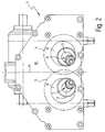
- FIG. 1 shows two stub shafts 2, 3, the one with a dashed line in FIG. 1 indicated picking roller structure 4, 5 two picking rollers 6, 7 surrender.
- the stub shafts 2, 3 are in storage boxes 8, 9 stored and open into a gear housing 10.
- Die Stumps 2, 3 are not parallel to each other arranged, but run at an acute angle ⁇ towards each other.
- This angled arrangement is according to the front view 2 clearly visible.
- they are Picking roller structures 4, 5 not shown in detail, but again indicated by dashed lines 4, 5.
- the structures 4, 5 grip when passing through the case Center axis 11 into one another.
- rollers could also be used here, it is advantageous to use the roller as possible in the rear area of closely spaced bearing points to store freely floating on the front.
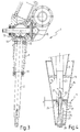
- Fig. 4 it can be seen how the picking roller 6 in two separate sections 16, 17 is divided. Any of these Parts 16, 17 have a conical roller structure 18, 19, each firmly with the corresponding shaft part 20, 21 connected, for example welded.
- the shaft parts 20, 21 comprise two together corresponding plug-in profiles 22, 23, one Form shaft coupling 24.
- the plug profiles 22, 23 can for example, be conical. However, there are also other profiles, for example polygon profiles or the like conceivable, both a good fit as well Ensure slip-free torque transmission.
- the insertion depth e is kept relatively short, so that the disassembly of the stalk roller 6 with a corresponding small displacement of the front section 17 at Pulling off the rear section 16 can be done.
- the front shaft part 21 is with a fastener attached to the rear shaft part 20.
- the front shaft part 21 with provided a hole through which a screw 26 passes which is in a threaded bore 27 of the rear shaft part 20 is screwed.
- An end plate 28 provides a uniform distribution of the screw 26th applied tension when attaching the two Parts 16, 17 to each other.
- Fig. 4 it can also be seen that the two sections 16, 17 in the present exemplary embodiment have different cone angles ⁇ or ⁇ .
- the insertion depth of the shaft coupling 24 is selected so that when pulling a section 17 this is not on the corresponding front sections of the neighboring Picking roller 7 abuts. This is especially angled The arrangement of the shaft ends 2, 3 must be observed.
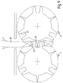
- FIG. 5 illustrates the function of the Picking rollers 6, 7.
- 4 driving elements 29, 30, 31, 32 each form the picking roller structure 4 and 5.
- Die Driving elements 29 to 32 are each pointed Cutting edge 33 provided.
- the envelopes 34, 35 are like this formed that two opposite cutting edges 33, 36, which when rotating the in phase and in opposite directions Picking rollers 6, 7 meet each other, a small distance between them.
- a plant stem 38 with fruit stands 39 for example a corn stalk with corn on the cob is cut by the two blades 33, 36 of the counter-moving elements 30, 37 of the picking rollers 6, 7 detected and down in the direction of the arrow P is drawn. Cut the cutting edges 33, 36 thereby the stem 38. While the stem 38 down the fear stands 39 on a scraper 40 picked.
- a picking roller structure according to this 5 is the plant stem in regular small pieces of length 2 ⁇ r / n cut, where r the radius of the envelopes 34, 35 and n the number of Driving elements 29, 30, 31, 32 corresponds.
- the picking rollers 6, 7 corresponds essentially to that 5, but now alternating between cutting driver elements 41, 42, 43 blunt driving elements 44, 45, 46 are arranged.
- the End regions 47 of the blunt drive elements 44, 45, 46 are arranged so that they do not reach the envelope 34. Therefore, the blunt drive elements 44, 45, 46 only squeezing functions and crush the Plant stem 38 not.
- the blunt drive elements 44, 45, 46 due to the lower number of cuts of energy required to drive the picking rollers 6, 7 reduced. Through the squeezing The effect of the blunt driving elements is still the Rotting favors because the entry is decomposing Organisms in the chopped material is facilitated.
- the picking rollers 6, 7 run in phase opposite, so that always correspondingly corresponding Take-along elements meet.
- the embodiment according to FIG. 7 in turn has alternating arranged cutting or blunt driving elements 41, 42, 43, 44, 45, 46. However, there are now between Driving elements deliberately larger free spaces 47, 48, 49, 50, 51, 52 provided, which can absorb crops.
- the Effect of this picking roller structure corresponds to that The embodiment described above, now a larger amount of other plant stem 38 Parts of plants, for example leaves or the like in the free spaces can be taken up. This avoids one any compression when passing between the stalk rollers 6, 7 which in turn reduces the energy requirement.
- FIGS. 5 to 7 are before especially suitable for the front picking roller areas where large pulling forces are desired because the fruit stands picked during the passage in this picking roller area become.
- the embodiment according to FIG. 8 shows two picking rollers 6, 7 with radially protruding driving elements 53, 54.
- the distance the picking roller 6, 7 is selected so that the envelopes 34, 35 overlap.
- the two picking rollers 6, 7 are operated here with a phase shift, so that one Driving element 54 of a picking roller 7 between two Engage driving elements 53 of the other picking roller 6 can.
- the plant stem 38 is thereby bent so that it breaks into pieces 55. With this arrangement achieve a short chopped crop, being crushed there is also good information.
- This structure is especially for the rear picking roller area, for example on the rear section 16 is advantageous because here lower entrainment forces due to the lack of fruit stands are required, however, the stalk must be taken along quickly is still required.
- the embodiment according to FIG. 9 is also primarily for the rear picking roller area is advantageous, now each point, cutting driving elements 56 alternating are arranged with hollow driving elements 57.
- the picking rollers 6, 7 are again so offset that a pointed driving element 56 in each hollow driving element 58 engages.
- This type of The stalk 38 not only breaks the stem 38, but cut at the same time. The chopped material is hereby crushed even more, resulting in a complete one Destruction of the stem structure can result.
- This Picking roller structure is again for use cases thought, where no high pull-in forces, however a faster pulling is desired, which in turn with the top Plant stem area and thus the rear Picking roller area corresponds.
- the sections 16, 17 are preferred provided with different picking roller structures.
- So 5 to 7 are the exemplary embodiments as o. a. especially for the front sections 17 as Roll structure suitable during the working examples 8 and 9 preferably on the rear sections 16 are attached.
- the angle ⁇ between the Stumps 2, 3 of the stalk rollers 6, 7 and the Cone angles ⁇ , ⁇ are on the outer contour of the one to be detected Adaptable external stem. With continuous threading the plant stem 38 passes the picking rollers 6, 7 in axial direction, so that in different Picking roller areas different Plant stem areas are processed.
- the roller structure 19 of the front section 17 is subject a higher wear, because the plant stem 38 in this picking roller area is located while the fruit stands 39 are picked on the stripper 40. This means that high driving forces are required in this area, whereby it partly to a certain slip between the Plant stems 38 and the corresponding roller structure 19 is coming. This results in the increased closure.
- the front section 17 for example, by simple Loosen the screw 26 and replace it, which rear section 16 can be used further. Of the Replacement of the front section 17 is without great Time required by loosening the single screw 26 possible. The Maintenance of the stalk roller 6 is thereby considerable simplified and especially cheaper.
Landscapes
- Life Sciences & Earth Sciences (AREA)
- Environmental Sciences (AREA)
- Harvesting Machines For Specific Crops (AREA)
Abstract
Description
- Fig. 1
- eine Draufsicht einer Erntevorrichtung mit zwei Pflückwalzen,
- Fig.2
- eine Frontansicht einer Vorrichtung gemäß Fig. 1,
- Fig. 3
- ein Längsschnitt durch eine Vorrichtung gemäß den Fig. 1 und 2,
- Fig. 4
- einen Längsschnitt durch eine erfindungsgemäße Pflückwalze,
- Fig. 5
- eine schematische Darstellung eines Ausführungsbeispiels für die Struktur eines Pflückwalzenbereichs,
- Fig. 6
- ein weiteres Ausführungsbeispiel für die Struktur eines Pflückwalzenbereichs,
- Fig. 7
- ein weiteres Ausführungsbeispiel für die Struktur eines Pflückwalzenbereichs,
- Fig. 8
- ein Ausführungsbeispiel für die Struktur eines Pflückwalzenbereichs mit ineinander greifenden Strukturelementen und
- Fig. 9
- eine weitere Ausführungsform eines Pflückwalzenbereichs mit ineinander greifenden Strukturelementen.
- 1.
- Vorrichtung
- 2.
- Wellenstumpf
- 3.
- Wellenstumpf
- 4.
- Pflückwalzenstruktur
- 5.
- Pflückwalzenstruktur
- 6.
- Pflückwalzen
- 7.
- Pflückwalzen
- 8.
- Lagerkasten
- 9.
- Lagerkasten
- 10.
- Getriebegehäuse
- 11.
- Mittelachse
- 12.
- Kugellager
- 13.
- Wälzlager
- 14.
- Kegelrad
- 15.
- Antriebswelle
- 16.
- Teilstück
- 17.
- Teilstück
- 18.
- Walzenstruktur
- 19.
- Walzenstruktur
- 20.
- Wellenteil
- 21.
- Wellenteil
- 22.
- Steckprofil
- 23.
- Steckprofil
- 24.
- Wellenkupplung
- 25.
- Bohrung
- 26.
- Schraube
- 27.
- Gewindebohrung
- 28.
- Abschlußplatte
- 29.
- Mitnahmeelement
- 30.
- Mitnahmeelement
- 31.
- Mitnahmeelement
- 32.
- Mitnahmeelement
- 33.
- Schneide
- 34.
- Hüllkurve
- 35.
- Hüllkurve
- 36.
- Schneide
- 37.
- Mitnahmeelement
- 38.
- Pflanzenstengel
- 39.
- Fruchtstand
- 40.
- Abstreifer
- 41.
- Mitnahmeelement
- 42.
- Mitnahmeelement
- 43.
- Mitnahmeelement
- 44.
- Mitnahmeelement
- 45.
- Mitnahmeelement
- 46.
- Mitnahmeelement
- 47.
- Mitnahmeelement
- 48.
- Freiraum
- 49.
- Freiraum
- 50.
- Freiraum
- 51.
- Freiraum
- 52.
- Freiraum
- 53.
- Mitnahmeelement
- 54.
- Mitnahmeelement
- 55.
- Teilstück
- 56.
- Mitnahmeelement
- 57.
- Mitnahmeelement
- 58.
- Mitnahmeelement
Claims (15)
- Vorrichtung zum Ernten von stengeligem Erntegut, wie Mais oder dergleichen, mit wenigstens einer Fördervorrichtung zur Förderung des Ernteguts entlang wenigstens einer Pflückwalze, dadurch gekennzeichnet, daß die Pflückwalze 6, 7 in axialer Richtung aus wenigsten zwei mit einander verbindbaren, separaten Teilstücken 16, 17 besteht.
- Vorrichtung nach Anspruch 1, dadurch gekennzeichnet, daß die Pflückwalze 6, 7 umfangsseitig Mitnahmeelemente 29, 30, 31, 32 zur Mitnahme der Pflanzenstengel 38 aufweist.
- Vorrichtung nach Anspruch 1 oder 2 dadurch gekennzeichnet, daß wenigstens zwei in axialer Richtung hintereinander liegende Strukturbereiche mit verschiedener Struktur 18, 19 der Mitnahmeelemente 29, 30, 31, 32 vorgesehen sind.
- Vorrichtung nach einem der vorgenannten Ansprüche, dadurch gekennzeichnet, daß wenigstens zwei separate Teilstücke 16, 17 der Pflückwalze 6 eine verschiedene Struktur 18, 19 der Mitnahmeelemente 29, 30, 31, 32 aufweisen.
- Vorrichtung nach einem der vorgenannten Ansprüche, dadurch gekennzeichnet, daß die Pflückwalzen 6, 7 wenigstens teilweise eine konische Form beinhaltet.
- Vorrichtung nach einem der vorgenannten Ansprüche, dadurch gekennzeichnet, daß unterschiedliche Konuswinkel β, γ in axialer Richtung vorgesehen sind.
- Vorrichtung nach einem der vorgenannten Ansprüche, dadurch gekennzeichnet, daß zwei separate Teilstücke 16, 17 mit unterschiedlichem Konuswinkel β, γ versehen sind.
- Vorrichtung nach einem der vorgenannten Ansprüche, dadurch gekennzeichnet, daß die Achsen zweier benachbarter Pflückwalzen 6, 7 unter einem Winkel α angeordnet sind.
- Vorrichtung nach einem der vorgenannten Ansprüche, dadurch gekennzeichnet, daß eine Steckkupplung 24 zwischen zwei Teilstücken 16, 17 einer Pflückwalze 6 vorgesehen ist.
- Vorrichtung nach einem der vorgenannten Ansprüche, dadurch gekennzeichnet, daß die Einstecktiefe e der Steckkupplung 24 an den Abstand a und den Winkel α zwischen zwei Pflückwalzen 6, 7 angepaßt ist.
- Vorrichtung nach einem der vorgenannten Ansprüche, dadurch gekennzeichnet, daß eine Walzenstruktur 18, 19 mit schneidenden Mitnahmeelementen 29, 30, 31, 32 vorgesehen ist.
- Vorrichtung nach einem der vorgenannten Ansprüche, dadurch gekennzeichnet, daß eine Walzenstruktur 18, 19 mit stumpfen Mitnahmeelementen 44, 45, 46 vorgesehen ist.
- Vorrichtung nach einem der vorgenannten Ansprüche, dadurch gekennzeichnet, daß zwei benachbarte Pflückwalzen 6, 7 einen gekoppelten Antrieb aufweisen, so daß korrespondierende Pflückwalzen 6, 7 phasengleich und gegenläufig umlaufen.
- Vorrichtung nach einem der vorgenannten Ansprüche, dadurch gekennzeichnet, daß gutaufnehmende Freiräume 48 zwischen Mitnahmeelementen in der Walzenstruktur 18, 19 vorgesehen sind.
- Vorrichtung nach einem der vorgenannten Ansprüche, dadurch gekennzeichnet, daß Mitnahmeelemente zweier benachbarter Pflückwalzen 6, 7 so ausgebildet sind, daß sich die Hüllkurven der Pflückwalzen 6, 7 schneiden.
Applications Claiming Priority (2)
| Application Number | Priority Date | Filing Date | Title |
|---|---|---|---|
| DE19811155 | 1998-03-14 | ||
| DE19811155 | 1998-03-14 |
Publications (2)
| Publication Number | Publication Date |
|---|---|
| EP0943229A1 true EP0943229A1 (de) | 1999-09-22 |
| EP0943229B1 EP0943229B1 (de) | 2003-08-27 |
Family
ID=7860928
Family Applications (1)
| Application Number | Title | Priority Date | Filing Date |
|---|---|---|---|
| EP99104805A Expired - Lifetime EP0943229B1 (de) | 1998-03-14 | 1999-03-11 | Vorrichtung zum Ernten von stengeligem Erntegut |
Country Status (2)
| Country | Link |
|---|---|
| EP (1) | EP0943229B1 (de) |
| DE (1) | DE59906721D1 (de) |
Cited By (11)
| Publication number | Priority date | Publication date | Assignee | Title |
|---|---|---|---|---|
| EP1305997A1 (de) | 2001-10-26 | 2003-05-02 | Maschinenfabrik Kemper GmbH & Co. KG | Pflückwalze |
| DE10250338A1 (de) * | 2002-10-29 | 2004-05-19 | Maschinenfabrik Kemper Gmbh & Co. Kg | Pflückwalze |
| EP2018801A1 (de) * | 2007-07-25 | 2009-01-28 | Deere & Company | Selbstreinigendes Reihengerät |
| US11129332B2 (en) * | 2018-06-29 | 2021-09-28 | Deere & Company | Corn stalk roll arrangement |
| US11800832B2 (en) | 2011-12-15 | 2023-10-31 | Calmer Holding Company, Llc | Stalk roll flute |
| US11882791B2 (en) | 2012-11-30 | 2024-01-30 | Calmer Holding Company, Llc | Narrow row head unit |
| US11937547B2 (en) * | 2018-08-03 | 2024-03-26 | Carl Geringhoff Gmbh & Co. Kg | Attachment for harvesting stalk-like stem crops with meshing picking rotors |
| USD1023700S1 (en) | 2019-02-12 | 2024-04-23 | Calmer Holding Company, Llc | Stalk roll |
| US12010949B2 (en) * | 2010-12-15 | 2024-06-18 | Calmer Holding Company, Llc | Stalk roll |
| US12029164B2 (en) | 2011-12-15 | 2024-07-09 | Calmer Holding Company, Llc | Stalk roll with multiple flutes of different lengths |
| US12279558B2 (en) | 2010-12-15 | 2025-04-22 | Calmer Holding Company, Llc | Stalk roll |
Families Citing this family (1)
| Publication number | Priority date | Publication date | Assignee | Title |
|---|---|---|---|---|
| WO2016118659A1 (en) | 2015-01-20 | 2016-07-28 | 360 Yield Center, Llc | Apparatus and method for management of harvest residue |
Citations (13)
| Publication number | Priority date | Publication date | Assignee | Title |
|---|---|---|---|---|
| US1641436A (en) * | 1924-04-25 | 1927-09-06 | Walter H Steimke | Snapping roll for corn harvesters |
| US2678526A (en) * | 1953-03-09 | 1954-05-18 | Herman H Voss | Snapping roll construction |
| US2905181A (en) * | 1958-01-10 | 1959-09-22 | Carl J Nelson | Corn picker roller |
| US2947133A (en) * | 1957-12-23 | 1960-08-02 | Int Harvester Co | Adjustable skewing of corn snapping rolls |
| US3633348A (en) * | 1970-03-25 | 1972-01-11 | Fmc Corp | Cornpicker head with reversible rotor blades |
| FR2453595A1 (fr) * | 1979-04-09 | 1980-11-07 | Revere Corp Paul | Rouleaux de prise pour tete de fauche |
| DE9105932U1 (de) * | 1990-05-18 | 1991-07-18 | Schulze Heuling, Ulrich, 4410 Warendorf | Schneidwalzenpaar für Maispflücker |
| US5040361A (en) * | 1990-02-27 | 1991-08-20 | Pixall Corporation | Snapping roller for a corn harvesting combine |
| DE4041530C1 (de) | 1990-12-22 | 1992-05-07 | Claas Ohg, 4834 Harsewinkel, De | |
| EP0716802A1 (de) | 1994-12-15 | 1996-06-19 | Claas Saulgau Gmbh | Einzugs- und Pflückvorrichtung für Mais |
| EP0852109A1 (de) * | 1996-12-06 | 1998-07-08 | New Holland Belgium N.V. | Modulare Pflückwalze mit einziger Schraubbolzen-Verbindung |
| DE19730912A1 (de) | 1997-07-18 | 1999-01-21 | Ludger Dipl Ing Wiegert | Erntegerät zum Ernten von Mais und anderen Körnerfrüchten |
| DE19757213C1 (de) | 1997-12-22 | 1999-02-18 | Roto Frank Ag | Scharnierbeschlag für den einen Überschlag aufweisenden Flügel eines Fensters, einer Tür oder dergleichen |
-
1999
- 1999-03-11 EP EP99104805A patent/EP0943229B1/de not_active Expired - Lifetime
- 1999-03-11 DE DE59906721T patent/DE59906721D1/de not_active Expired - Lifetime
Patent Citations (13)
| Publication number | Priority date | Publication date | Assignee | Title |
|---|---|---|---|---|
| US1641436A (en) * | 1924-04-25 | 1927-09-06 | Walter H Steimke | Snapping roll for corn harvesters |
| US2678526A (en) * | 1953-03-09 | 1954-05-18 | Herman H Voss | Snapping roll construction |
| US2947133A (en) * | 1957-12-23 | 1960-08-02 | Int Harvester Co | Adjustable skewing of corn snapping rolls |
| US2905181A (en) * | 1958-01-10 | 1959-09-22 | Carl J Nelson | Corn picker roller |
| US3633348A (en) * | 1970-03-25 | 1972-01-11 | Fmc Corp | Cornpicker head with reversible rotor blades |
| FR2453595A1 (fr) * | 1979-04-09 | 1980-11-07 | Revere Corp Paul | Rouleaux de prise pour tete de fauche |
| US5040361A (en) * | 1990-02-27 | 1991-08-20 | Pixall Corporation | Snapping roller for a corn harvesting combine |
| DE9105932U1 (de) * | 1990-05-18 | 1991-07-18 | Schulze Heuling, Ulrich, 4410 Warendorf | Schneidwalzenpaar für Maispflücker |
| DE4041530C1 (de) | 1990-12-22 | 1992-05-07 | Claas Ohg, 4834 Harsewinkel, De | |
| EP0716802A1 (de) | 1994-12-15 | 1996-06-19 | Claas Saulgau Gmbh | Einzugs- und Pflückvorrichtung für Mais |
| EP0852109A1 (de) * | 1996-12-06 | 1998-07-08 | New Holland Belgium N.V. | Modulare Pflückwalze mit einziger Schraubbolzen-Verbindung |
| DE19730912A1 (de) | 1997-07-18 | 1999-01-21 | Ludger Dipl Ing Wiegert | Erntegerät zum Ernten von Mais und anderen Körnerfrüchten |
| DE19757213C1 (de) | 1997-12-22 | 1999-02-18 | Roto Frank Ag | Scharnierbeschlag für den einen Überschlag aufweisenden Flügel eines Fensters, einer Tür oder dergleichen |
Cited By (20)
| Publication number | Priority date | Publication date | Assignee | Title |
|---|---|---|---|---|
| EP1305997A1 (de) | 2001-10-26 | 2003-05-02 | Maschinenfabrik Kemper GmbH & Co. KG | Pflückwalze |
| DE10250338A1 (de) * | 2002-10-29 | 2004-05-19 | Maschinenfabrik Kemper Gmbh & Co. Kg | Pflückwalze |
| US7237373B2 (en) | 2002-10-29 | 2007-07-03 | Maschinenfabrik Kemper Gmbh & Co. Kg | Stalk roll with oppositely tapering body and drivers |
| EP2018801A1 (de) * | 2007-07-25 | 2009-01-28 | Deere & Company | Selbstreinigendes Reihengerät |
| US7716908B2 (en) | 2007-07-25 | 2010-05-18 | Deere & Company | Self-clearing row unit and stalk roll |
| US12279558B2 (en) | 2010-12-15 | 2025-04-22 | Calmer Holding Company, Llc | Stalk roll |
| US12225851B2 (en) | 2010-12-15 | 2025-02-18 | Calmer Holding Company, Llc | Stalk roll with wide engagement gap |
| US12010949B2 (en) * | 2010-12-15 | 2024-06-18 | Calmer Holding Company, Llc | Stalk roll |
| US11800832B2 (en) | 2011-12-15 | 2023-10-31 | Calmer Holding Company, Llc | Stalk roll flute |
| US12295289B2 (en) | 2011-12-15 | 2025-05-13 | Calmer Holding Company, Llc | Stalk roll |
| US12029164B2 (en) | 2011-12-15 | 2024-07-09 | Calmer Holding Company, Llc | Stalk roll with multiple flutes of different lengths |
| US12232447B2 (en) | 2011-12-15 | 2025-02-25 | Calmer Holding Company, Llc | Stalk roll with progressively increasing engagement gap |
| US12342758B2 (en) | 2012-11-30 | 2025-07-01 | Calmer Holding Company, Llc | Actuated stripper plate mechanism for a harvester |
| US11882791B2 (en) | 2012-11-30 | 2024-01-30 | Calmer Holding Company, Llc | Narrow row head unit |
| US11129332B2 (en) * | 2018-06-29 | 2021-09-28 | Deere & Company | Corn stalk roll arrangement |
| US11937547B2 (en) * | 2018-08-03 | 2024-03-26 | Carl Geringhoff Gmbh & Co. Kg | Attachment for harvesting stalk-like stem crops with meshing picking rotors |
| US12150410B2 (en) | 2019-02-12 | 2024-11-26 | Calmer Holding Company, Llc | Twelve bladed stalk roll |
| US11997950B2 (en) | 2019-02-12 | 2024-06-04 | Calmer Holding Company, Llc | 12 bladed stalk roll |
| USD1023700S1 (en) | 2019-02-12 | 2024-04-23 | Calmer Holding Company, Llc | Stalk roll |
| US12433195B2 (en) | 2019-02-12 | 2025-10-07 | Calmer Holding Company, Llc | Twelve flutes for stalk roll |
Also Published As
| Publication number | Publication date |
|---|---|
| EP0943229B1 (de) | 2003-08-27 |
| DE59906721D1 (de) | 2003-10-02 |
Similar Documents
| Publication | Publication Date | Title |
|---|---|---|
| EP1417877B1 (de) | Pflückwalze | |
| DE3013689A1 (de) | Schnappwalzen fuer das ernten von maiskolben | |
| DE69915452T2 (de) | Brechwalzeneinheit für ein Maiserntevorsatzgerät | |
| EP0369440B1 (de) | Verfahren und Vorrichtung zum Ernten von Fruchtständen | |
| DD209561B5 (de) | Erntegeraet zum Ernten von Mais oder anderen Koernerfruechten | |
| EP2404496A2 (de) | Maispflücker | |
| DE4036717A1 (de) | Pflueckvorsatz fuer ein erntegeraet | |
| DE19959281A1 (de) | Einzugs- und Pflückeinrichtung einer Erntegutbergungsvorrichtung | |
| DE19959338A1 (de) | Einzugs- und Pflückeinrichtung sowie Erntemaschine | |
| DE102012014085A1 (de) | Pflückeinheit, Erntevorsatz und Erntemaschine für Mais oder dergleichen | |
| EP0943229B1 (de) | Vorrichtung zum Ernten von stengeligem Erntegut | |
| EP3829289B1 (de) | Vorsatzgerät zur ernte von stängeligem halmgut | |
| DE102005054998A1 (de) | Pflückwalze | |
| DE10257776A1 (de) | Einzugs- und Pflückeinrichtung | |
| DE2303528C3 (de) | Maishäcksler | |
| DE19811156A1 (de) | Vorrichtung zum Ernten von stengeligem Erntegut | |
| DE2010082A1 (de) | ||
| DE10026495A1 (de) | Erntegerät | |
| DE9105932U1 (de) | Schneidwalzenpaar für Maispflücker | |
| EP0716802A1 (de) | Einzugs- und Pflückvorrichtung für Mais | |
| EP1129610A1 (de) | Einzugs- und Pflückeinrichtung einer Erntegutbergungsmaschine | |
| DE8600113U1 (de) | Einzugs- und Rippenwalze für den Maispflückvorsatz eines Mähdreschers | |
| EP1493319B1 (de) | Einzugs- und Pflückeinrichtung | |
| DE29909358U1 (de) | Pflückvorsatz für Geräte zum Ernten von Körnerfrüchten | |
| DE102019007585A1 (de) | Reihenunabhängiges Vorsatzgerät zum Ernten stängelförmiger Pflanzen mit einem quer zur Fahrtrichtung liegenden, durch das ganze Vorsatzgerät durchgehenden Pflückspalt |
Legal Events
| Date | Code | Title | Description |
|---|---|---|---|
| PUAI | Public reference made under article 153(3) epc to a published international application that has entered the european phase |
Free format text: ORIGINAL CODE: 0009012 |
|
| AK | Designated contracting states |
Kind code of ref document: A1 Designated state(s): BE DE FR IT |
|
| AX | Request for extension of the european patent |
Free format text: AL;LT;LV;MK;RO;SI |
|
| 17P | Request for examination filed |
Effective date: 20000322 |
|
| AKX | Designation fees paid |
Free format text: BE DE FR IT |
|
| 17Q | First examination report despatched |
Effective date: 20010814 |
|
| GRAH | Despatch of communication of intention to grant a patent |
Free format text: ORIGINAL CODE: EPIDOS IGRA |
|
| GRAS | Grant fee paid |
Free format text: ORIGINAL CODE: EPIDOSNIGR3 |
|
| GRAA | (expected) grant |
Free format text: ORIGINAL CODE: 0009210 |
|
| AK | Designated contracting states |
Designated state(s): BE DE FR IT |
|
| REF | Corresponds to: |
Ref document number: 59906721 Country of ref document: DE Date of ref document: 20031002 Kind code of ref document: P |
|
| ET | Fr: translation filed | ||
| PLBE | No opposition filed within time limit |
Free format text: ORIGINAL CODE: 0009261 |
|
| STAA | Information on the status of an ep patent application or granted ep patent |
Free format text: STATUS: NO OPPOSITION FILED WITHIN TIME LIMIT |
|
| 26N | No opposition filed |
Effective date: 20040528 |
|
| REG | Reference to a national code |
Ref country code: FR Ref legal event code: PLFP Year of fee payment: 17 |
|
| PGFP | Annual fee paid to national office [announced via postgrant information from national office to epo] |
Ref country code: FR Payment date: 20150319 Year of fee payment: 17 |
|
| REG | Reference to a national code |
Ref country code: DE Ref legal event code: R084 Ref document number: 59906721 Country of ref document: DE |
|
| PGFP | Annual fee paid to national office [announced via postgrant information from national office to epo] |
Ref country code: DE Payment date: 20160127 Year of fee payment: 18 |
|
| PGFP | Annual fee paid to national office [announced via postgrant information from national office to epo] |
Ref country code: BE Payment date: 20160321 Year of fee payment: 18 |
|
| PGFP | Annual fee paid to national office [announced via postgrant information from national office to epo] |
Ref country code: IT Payment date: 20160324 Year of fee payment: 18 |
|
| REG | Reference to a national code |
Ref country code: FR Ref legal event code: ST Effective date: 20161130 |
|
| PG25 | Lapsed in a contracting state [announced via postgrant information from national office to epo] |
Ref country code: FR Free format text: LAPSE BECAUSE OF NON-PAYMENT OF DUE FEES Effective date: 20160331 |
|
| REG | Reference to a national code |
Ref country code: DE Ref legal event code: R119 Ref document number: 59906721 Country of ref document: DE |
|
| PG25 | Lapsed in a contracting state [announced via postgrant information from national office to epo] |
Ref country code: DE Free format text: LAPSE BECAUSE OF NON-PAYMENT OF DUE FEES Effective date: 20171003 |
|
| PG25 | Lapsed in a contracting state [announced via postgrant information from national office to epo] |
Ref country code: IT Free format text: LAPSE BECAUSE OF NON-PAYMENT OF DUE FEES Effective date: 20170311 |
|
| REG | Reference to a national code |
Ref country code: BE Ref legal event code: MM Effective date: 20170331 |
|
| PG25 | Lapsed in a contracting state [announced via postgrant information from national office to epo] |
Ref country code: BE Free format text: LAPSE BECAUSE OF NON-PAYMENT OF DUE FEES Effective date: 20170331 |