EP0943459B1 - Méthode pour retourner des assemblages pliés - Google Patents
Méthode pour retourner des assemblages pliés Download PDFInfo
- Publication number
- EP0943459B1 EP0943459B1 EP99104095A EP99104095A EP0943459B1 EP 0943459 B1 EP0943459 B1 EP 0943459B1 EP 99104095 A EP99104095 A EP 99104095A EP 99104095 A EP99104095 A EP 99104095A EP 0943459 B1 EP0943459 B1 EP 0943459B1
- Authority
- EP
- European Patent Office
- Prior art keywords
- collation
- plate assembly
- fold plate
- stop member
- folded
- Prior art date
- Legal status (The legal status is an assumption and is not a legal conclusion. Google has not performed a legal analysis and makes no representation as to the accuracy of the status listed.)
- Expired - Lifetime
Links
- 238000000034 method Methods 0.000 title claims description 17
- 230000000694 effects Effects 0.000 claims description 3
- 238000012545 processing Methods 0.000 claims description 2
- 238000003780 insertion Methods 0.000 description 15
- 230000037431 insertion Effects 0.000 description 15
- 238000007789 sealing Methods 0.000 description 5
- 238000012423 maintenance Methods 0.000 description 1
- 238000012986 modification Methods 0.000 description 1
- 230000004048 modification Effects 0.000 description 1
- 230000000717 retained effect Effects 0.000 description 1
- 238000012549 training Methods 0.000 description 1
Images


Classifications
-
- B—PERFORMING OPERATIONS; TRANSPORTING
- B43—WRITING OR DRAWING IMPLEMENTS; BUREAU ACCESSORIES
- B43M—BUREAU ACCESSORIES NOT OTHERWISE PROVIDED FOR
- B43M3/00—Devices for inserting documents into envelopes
- B43M3/04—Devices for inserting documents into envelopes automatic
- B43M3/045—Devices for inserting documents into envelopes automatic for envelopes with only one flap
-
- B—PERFORMING OPERATIONS; TRANSPORTING
- B65—CONVEYING; PACKING; STORING; HANDLING THIN OR FILAMENTARY MATERIAL
- B65H—HANDLING THIN OR FILAMENTARY MATERIAL, e.g. SHEETS, WEBS, CABLES
- B65H15/00—Overturning articles
- B65H15/02—Overturning piles
-
- B—PERFORMING OPERATIONS; TRANSPORTING
- B65—CONVEYING; PACKING; STORING; HANDLING THIN OR FILAMENTARY MATERIAL
- B65H—HANDLING THIN OR FILAMENTARY MATERIAL, e.g. SHEETS, WEBS, CABLES
- B65H15/00—Overturning articles
- B65H15/004—Overturning articles employing rollers
Definitions
- the present invention relates generally to document inserting system, which assemble documents and inserts for insertion into envelopes. More particularly, the present invention is directed toward a method for inverting the travel direction of a half-folded document in an inserter system.
- WO 97/28972 discloses a fold plate assembly.
- Document inserting systems generally include a plurality of various stations that are each configured for a specific task.
- an inserter system typically includes at least one sheet feeding mechanism for supplying a sheet from a supply.
- an inserter system includes a collating mechanism located downstream of the sheet feeding mechanism that is functional to collate one or more sheets designated to be inserted into an envelope.
- a folding mechanism is usually located downstream of the collaring mechanism and is operational to fold sheet collation a prescribed format. Examples of such folded formats include a z-fold, a c-fold, a half-fold, double-fold, etc.
- An insertion station is typically located downstream of the folding mechanism and is operational to insert the folded collation into a waiting open envelope.
- Inserter systems are used by organizations such as banks, insurance companies and utility companies for producing a large volume of specific mailings where the contents of each mail item are directed to a particular addressee. Additionally other organizations, such as direct mailers, use inserts for producing a large volume of generic mailings where the contents of each mail item are substantially identical for each addressee. Examples of such high volume inserter systems are the 8,9 and 14 series inserter systems available from Pitney Bowes. Inc., Stamford, Connecticut.
- inserter systems are not limited to such high volume applications as they also have considerably utility in lower volume applications, such as SOHO (small office/home office) applications.
- SOHO small office/home office
- An example of such a SOHO inserter system is the tabletop 3 Series inserter system available from Pitney Bowes Limited, Harlow, England.
- This inserter system has been designed for implementation on an tabletop surface while providing many automated features and requiring little maintenance. In other words, it has been designed to be operated by an ordinary office worker with little or no training in operating inserter systems. Therefore, regarding the operation of such inserters, it is critical that they provide many automated and self adjusting features while having a. high degree of reliability.
- One such area of an inserter where automation and reliability is extremely important is the folding station.
- a known difficulty associated with folding stations is when it desired to invert the travel direction of a half-folded collation in the folding station of an inserter. It is desirable to invert the travel direction of a half folded collation (also known as a single-folded document) when it is required reorient the addressing text printed on a sheet so as to be properly orient that text with respect to an envelope window when inserted Therein.
- a spring loaded stop was implemented in one of the folding plates to effect the change of direction of a half-folded document.
- spring loaded stops are costly as they require added and often prove unreliably.
- the instant invention provides from one aspect, a method of inverting the travel direction of a folded collation consisting of at least one sheet, comprising the steps of conveying the collation at least partially into a fold plate assembly through a proximal end thereof and into abutment with a movable stop member in the fold plate assembly at a distal position and moving the stop member from said distal position to a proximal position to cause the collation to convey out of the fold plate assembly.
- the instant invention provides from another aspect, a fold plate assembly having a proximal end, means for conveying a folded collation consisting of at least one sheet at least partially into said fold plate assembly through said proximal end and into abutment with a movable stop member in the fold plate assembly at a distal position, and means operable for moving the stop member from said distal position to a proximal position to cause the collation to convey out of the fold plate assembly.
- the means operable for moving the stop member comprises a control system coupled to the stop member in the second fold plate assembly and operative to move the stop member between its distal and proximal positions.
- a collation is initially conveyed to the first fold plate assembly such that a leading edge portion of the collation is disposed in the first fold plate assembly and a mid-point portion of the collation is in engagement with the folding roller assembly.
- the collation is conveyed through the folding roller assembly to the second fold plate assembly such that the mid-point portion of the collation is caused to be folded in the fording roller assembly, which, folded portion is conveyed to, and abuts against the stop member in the second fold plate assembly.
- the stop member in the second fold, plate assembly is then moved from the distal position to proximal position with a signal from the control system so as to cause the collation to convey out of the second fold plate assembly and folding station.
- FIG. 1 an elevational view of a table top inserter, designated generally at 10, which includes a folding station, designated generally at 100.
- inserter system 10 of Fig. 1 only to show an exemplary environment of implementation for the folding station 100.
- inserter system 10 is not to be understood to be the only environment of use for folding station 100 as one skilled in the art could readily implement the below described folding station 100 in various inserter systems requiring a folding station or in any mechanism requiring a folding station for folding sheets of paper. Therefore, in order not to obscure the folding station 100, only a general description of the inserter system 10 depicted in Fig. 1 will be provided.
- GB-A-2 292 937 Application No. 9418333.2
- tabletop inserter 10 generally consists of an upper housing 12 mounted atop a lower housing 14.
- Upper housing 12 generally includes first and second sheet feeders 16 and 18, and preferably an insert feeder 20.
- Individual sheets are preferably conveyed from each sheet feeder 16 and 18 into respectively fast and second feed paths 22 and 24.
- the fast and second sheet paths 22 and 24 merge with one another at a collation station 26 having fast and second collating rollers 28 and 29.
- the collation station 26 is operative to align the leading edges of first and second sheets being respectively conveyed from the first and second sheets feeders 16 and 18 (via the first and second sheet paths 22 and 24) within the nip formed between the collating rollers 28 and 29.
- the collating rollers 28 and 29 are actuated to simultaneously feed the aligned sheets in a supply path 30 downstream of the collating station 26.
- These aligned sheets are also commonly known as a "collation" This sheet collation is then conveyed downstream in the supply path 30 to the folding station 100.
- the folding station 100 is configured to fold a sheet collation in prescribed formats, such as, c-fold, z-fold, half-fold, etc.
- the preferred embodiment folding station 100 half-folds a collation in conjunction a first fold plate 102 and inverts the travel direction of the half-folded collation in a second fold-plate 104. After a collation is folded in the folding station 100, the collation is then conveyed to the lower housing 14 of the inserter system 10 for further processing.
- the lower housing 14 of inserter system 10 includes an envelope supply station 40 connecting to an insertion station 42.
- the envelope supply station 40 feeds envelopes to the insertion station 42 (via envelope feed path 44).
- an envelope is retained in preparation for insertion of the aforesaid folded collation being conveyed from the folding station 100.
- the folded collation is transported from the folding station 100 to the insertion station 42 via a collation transport path 46 connecting the later two stations.
- the collation transport path 46 includes a pair of conveying rollers 48 and 50 for conveying a folded collation along the transport path 46.
- the lower housing 14 further includes a sealing station 52 located downstream of the insertion station 42, which sealing station 52 is operative to seal an open envelope - received from the insertion station 42.
- An envelope insertion path connects the insertion station 42 to the sealing station 52.
- An envelope output path 56 connects to the sealing station 52 and is operative to convey sealed envelopes from the sealing station 52 through an output opening 58 provided in the lower housing 14 of the insertion system 10. After a sealed envelope has exited from the output opening 58 appropriate postage can then be applied for delivery to a recipient
- inserter system 10 includes a control system 70 (Fig. 2) for controlling the various components implemented in the inserter system 10. It is to be appreciated that the control system 70 is to encompass a computer processor driven system.
- the folding station 100 includes the first and second folding plates 102 and 104, and first, second, third and fourth folding rollers 106, 108, 110 and 112.
- first and third folding rollers 106 and 110 continuously rotate in a clockwise rotation
- second and fourth folding rollers 108 and 112 continuously rotate in a counter-clockwise direction.
- All the later folding rollers preferably rotate at a common speed, which rotation is caused by preferably a AC motor (not shown).
- Each folding plate 102 and 104 defines a channel 120 and 122 through which extends a movable stop member 124 and 126.
- Each stop member 124 and 126 extends from a carriage assembly 128 and 130 and is connected to a respective motor assembly 132 and 134 for moving each respective stop member 124 and 126 through each respective folding plate channel 120 and 122.
- Each motor assembly 132 and 134 is preferably connected to, and controlled by, the control system 70 of the inserter system 10.
- Each folding plate 102 and 104 further includes a sensor element 136 and 138 mounted in proximity to the entrance of each respective fold plate channel 120 and 122.
- Each sensor 136 and 138 is connected to the control system 70 and is operative to detect the presence of a collation residing above each sensor 136 and 138. It is noted that the sensor 138 in the second folding plate 104 is also operative to signal when an insert is to be fed from an insert station (not shown) so as to be properly nested with the collation in the folding station 100.
- control system 70 is operative to position each stop member 124 and 126 in each respective fold plate 102 and 104 at a predetermined position to achieve the chosen fold (e.g., z-fold, c-fold, half-fold, double-fold, etc.).
- a predetermined position e.g., z-fold, c-fold, half-fold, double-fold, etc.
- the chosen fold e.g., z-fold, c-fold, half-fold, double-fold, etc.
- the first fold plate stop member 124 is moved in the first fold plate 102 (via motor 132) to a half-fold position to effect a collation to be half-folded by the nip formed between the second aad third folding rollers 108 and 110.
- the second fold plate stop member 126 is moved in the second fold plate 104 (via motor 134) to an entry position 150 that permits a half-folded collation to substantially reside in the folding channel 122 of the second fold plate 104, the significance of which will be appreciated below.
- a single page collation 200 is feed from one of the sheet feeding stations 16 and 18 into the supply path 200 (via rollers 28 and 29).
- the collation being used in the present description is not to be limited to a single page collation but may consist of a plurality of pages being feed from a plurality of sheet feeding stations.
- the collation 200 is conveyed into the nip formed between the first and second folding rollers 106 and 108. The collation 200 is then caused to advance into the channel 120 of the first folding plate 102.
- the mid-point 202 of the collation 200 will then start to buckle into the nip of the second and third folding rollers 108 and 110 since the first and second folding rollers 106 and 108 are continuing to drive the tail portion of the collation 200.
- the mid-point 202 of the collation 200 is then caused to engage into the folding nip of the second and third folding rollers 108 and 110 causing the collation 200 to fold at its mid-point 202 and convey towards and into the second fold plate 104 (via the second and third folding rollers 108 and 110).
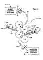
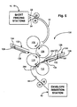
- the folded collation 200 then conveys past the second sensor 138 until the folded leading edge 202 abuts against the second fold plate stop member 126, as shown in Fig. 5.
- the second fold plate stop member 126 is caused to convey (via motor 134) toward the third and fourth folding rollers 110 and 112 and toward an engagement position 152 so as to cause the open edge 204 of the folded collation 200 to engage within the nip formed between the third and fourth folding rollers 110 and 112.
- the folded collation 200 With reference to Fig. 7, the folded collation 200, with it's open end 204 leading, is then caused to travel along the envelope feed path 44 and into the envelope insertion station 42 (via rollers 48 and 50). Once in the envelope insertion station 42, the folded collation 200 is then preferably inserted into an envelope.
- the travel direction of the half-folded folded collation 200 is inverted in the second fold plate 104 of the folding station 100. That is, the half-folded collation 200 enters into the second folding plate 104 with its folded edge 202 leading and its open edge 204 trailing, but exits the second folding plate 104, and the folding station 100, with its open edge 204 leading and its folded edge 202 trailing.
- the leading folded edge 202 of the collation is leading and conveying from the second and third folding rollers 108 and 110 and towards the second folding plate 104 (Fig. 5)
- the leading folded edge 202 first passes over the second sensor 138 as it enters into the second folding plate 104.
- the second sensor 138 detects that passage of the folded collation 200 in the second folding plate 204 and preferably sends a signal to the control system 70 informing it of the presence of the collation 200.
- the controls system 70 sends a signal to the second fold plate stop member 126 (via motor 134) to advance the stop member 126 from its entry position 150 to its engagement position 152 5o as to advance the collation 200 out of the second folding plate 104 and toward the nip formed by the third and fourth folding rollers 110 and 112, which rollers convey the collation 200 to the insertion station 42 (via transport path 46).
- the folded collation 200 is conveyed out of the second folding plate 104 by the second stop member 126 only after the open trailing edges 204 of the collation have exited from the nip of the second and third foldmg rollers 108 and 110 so as motto cause another fold in the collation 200.
- the second fold plate stop member 126 then preferably advances towards its home position 154 (Fig. 2) whereby the control system 70 resets the stop member 126 to its home calibration position 154, as detected by sensor 138. Thereafter, the second stop member 126 is returned to its entry position 152 (Fig. 3) enabling the control system 70 to ensure that the stop member 126 is in its intended position for inverting the travel direction of another half-folded collation in accordance with the above described method.
Landscapes
- Engineering & Computer Science (AREA)
- Mechanical Engineering (AREA)
- Folding Of Thin Sheet-Like Materials, Special Discharging Devices, And Others (AREA)
Claims (11)
- Procédé d'inversion du sens de déplacement d'un assemblage plié se composant d'au moins une feuille, comprenant les étapes consistant à transporter l'assemblage au moins en partie jusque dans un ensemble de plateau de pliage (104) à travers une extrémité proximale de celui-ci et en butée avec un organe d'arrêt mobile (126) dans l'ensemble de plateau de pliage au niveau d'une position distale (150) et à déplacer l'organe d'arrêt de ladite position distale à une position proximale (152) de façon à faire transporter l'assemblage hors de l'ensemble de plateau de pliage.
- Procédé selon la revendication 1 pour traiter un assemblage se composant d'au moins une feuille dans une station de pliage (100) ayant un ensemble de rouleaux plieurs (106, 108, 110, 112), un autre ensemble de plateau de pliage (102), le premier ensemble de plateau de pliage mentionné (104) se situant en aval de l'ensemble de rouleaux plieurs et du deuxième ensemble de plateau de pliage mentionné, dans lequel, avant que l'assemblage soit transporté jusque dans le premier ensemble de plateau mentionné (104),au moins une partie de l'assemblage est transportée jusque dans le deuxième ensemble de plateau de pliage mentionné (102) de façon à former l'assemblage plié ; etl'assemblage plié est transporté à partir du deuxième ensemble de plateau de pliage mentionné par l'intermédiaire de l'ensemble de rouleaux plieurs.
- Procédé selon la revendication 2, comprenant en outre l'étape consistant à:plier à moitié l'assemblage dans l'ensemble de rouleaux plieurs (106, 108, 110, 112) quand l'assemblage est transporté du deuxième ensemble de plateau de pliage mentionné (102) au deuxième ensemble de plateau de pliage (104), dans lequel l'assemblage à moitié plié a un bord plié (202) et un bord ouvert (204) de telle sorte que le bord plié est transporté en premier jusque dans le deuxième ensemble de plateau de pliage et mis en butée contre l'organe d'arrêt (126) dans le deuxième ensemble de plateau de pliage (104).
- Procédé selon la revendication 3, comprenant en outre l'étape consistant à transporter l'assemblage à moitié plié jusque dans le premier ensemble de plateau de pliage mentionné (104) de telle manière que l'assemblage à moitié plié est dégagé de l'ensemble de rouleaux plieurs.
- Procédé selon la revendication 3 ou 4, comprenant en outre l'étape consistant à déplacer l'organe d'arrêt (126) dans le premier ensemble de plateau de pliage mentionné (104) de la position proximale (152) à la position distale (150) après que l'assemblage à moitié plié a été transporté hors du premier ensemble de plateau de pliage mentionné (104).
- Procédé selon la revendication 5, comprenant en outre les étapes consistant à :placer un système de commande (70) couplé à l'organe d'arrêt (126) dans le premier ensemble de plateau de pliage mentionné (104) et servant à déplacer l'organe d'arrêt (126) entre ses positions distale (150) et proximale (152) ; ettransmettre un signal du système de commande à l'organe d'arrêt de façon à déplacer l'organe d'arrêt entre les positions distale et proximale dans le premier ensemble de plateau de pliage mentionné.
- Procédé selon la revendication 1 pour plier à moitié un assemblage d'au moins une feuille, dans lequel :au moins une partie de l'assemblage est transportée jusque dans le premier ensemble de plateau de pliage (102) de telle manière qu'une partie de bord avant de l'assemblage est disposée dans le premier ensemble de plateau de pliage et qu'une partie centrale de l'assemblage est en prise avec l'ensemble de rouleaux plieurs ;l'assemblage est transporté du premier ensemble de plateau de pliage mentionné, par l'intermédiaire de l'ensemble de rouleaux plieurs, au moins en partie jusque dans le premier ensemble de plateau de pliage mentionné (104) de telle manière que la partie centrale de l'assemblage se fait plier dans l'ensemble de rouleaux plieurs, laquelle partie pliée est transportée jusqu'à, et vient en butée contre, l'organe d'arrêt (126) dans le deuxième ensemble de plateau de pliage ; etl'organe d'arrêt est déplacé de la position distale (150) à la position proximale (152) en réponse à un signal d'un système de commande couplé à l'organe d'arrêt dans le deuxième ensemble de plateau de pliage et servant à déplacer l'organe d'arrêt entre ses positions distale et proximale de façon à faire transporter l'assemblage hors du premier ensemble de plateau de pliage mentionné et de la station de pliage.
- Procédé selon la revendication 7, comprenant en outre l'étape consistant à transporter l'assemblage à moitié plié jusque dans le premier ensemble de plateau de pliage mentionné (104) de telle façon que l'assemblage à moitié plié soit dégagé de l'ensemble de rouleaux plieurs.
- Procédé selon la revendication 7 ou 8, comprenant en outre l'étape consistant à ramener l'organe d'arrêt (126) dans le deuxième ensemble de plateau de pliage (104) de la position proximale (152) à la position distale (150) par un signal du système de commande (70) après que l'assemblage à moitié plié a été transporté hors du premier ensemble de plateau de pliage mentionné (104).
- Procédé selon la revendication 7, 8 ou 9, comprenant en outre les étapes consistant à :placer un organe d'arrêt mobile (124) dans le premier ensemble de plateau (102) qui est couplé au système de commande (70) de telle manière qu'un signal du système de commande produise un positionnement de l'organe d'arrêt mobile dans le deuxième ensemble de plateau de pliage mentionné ; etpositionner l'organe d'arrêt mobile dans le deuxième ensemble de plateau de pliage mentionné avec un signal du système de commande de façon à faire plier à moitié un assemblage par l'ensemble de rouleaux plieurs.
- Ensemble de plateau de pliage ayant une extrémité proximale, des moyens (108, 110) permettant de transporter un assemblage plié, se composant d'au moins une feuille, au moins en partie jusque dans ledit ensemble de plateau de pliage (104) à travers ladite extrémité proximale et en butée avec un organe d'arrêt mobile (126) dans l'ensemble de plateau de pliage (104) au niveau d'une position distale (150), et des moyens (170) servant à déplacer l'organe d'arrêt (126) de ladite position distale (150) à une position proximale (152) de façon à faire transporter l'assemblage hors de l'ensemble de plateau de pliage.
Applications Claiming Priority (3)
| Application Number | Priority Date | Filing Date | Title |
|---|---|---|---|
| GBGB9805907.4A GB9805907D0 (en) | 1998-03-19 | 1998-03-19 | Method for inverting a folded collation |
| GB9805907 | 1998-03-19 | ||
| US09/274,045 US6206816B1 (en) | 1998-03-19 | 1999-03-22 | Method for inverting a folded collation |
Publications (2)
| Publication Number | Publication Date |
|---|---|
| EP0943459A1 EP0943459A1 (fr) | 1999-09-22 |
| EP0943459B1 true EP0943459B1 (fr) | 2003-09-24 |
Family
ID=26313310
Family Applications (1)
| Application Number | Title | Priority Date | Filing Date |
|---|---|---|---|
| EP99104095A Expired - Lifetime EP0943459B1 (fr) | 1998-03-19 | 1999-03-18 | Méthode pour retourner des assemblages pliés |
Country Status (2)
| Country | Link |
|---|---|
| US (1) | US6206816B1 (fr) |
| EP (1) | EP0943459B1 (fr) |
Families Citing this family (18)
| Publication number | Priority date | Publication date | Assignee | Title |
|---|---|---|---|---|
| GB9828784D0 (en) * | 1998-12-29 | 1999-02-17 | Pitney Bowes Ltd | Inserter system |
| GB0123405D0 (en) * | 2001-09-28 | 2001-11-21 | Pitney Bowes Ltd | Apparatus for collating sheets |
| DE50106223D1 (de) * | 2001-12-11 | 2005-06-16 | Oppenweiler Binder Gmbh Maschb | Verfahren zur Einstellung der Falzspaltenweite mehrerer Falzwalzenpaare. |
| US6648319B2 (en) * | 2001-12-14 | 2003-11-18 | Pitney Bowes Inc. | Apparatus for collating sheets |
| DE20218159U1 (de) * | 2002-11-22 | 2003-01-16 | Maschinenbau Oppenweiler Binder GmbH & Co. KG, 71570 Oppenweiler | Taschenfalzwerk für eine Falzmaschine |
| JP2004284742A (ja) * | 2003-03-20 | 2004-10-14 | Fuji Xerox Co Ltd | シート折り装置、シート処理装置及び画像形成装置 |
| JP4189583B2 (ja) * | 2003-07-24 | 2008-12-03 | コニカミノルタビジネステクノロジーズ株式会社 | 用紙折り装置、用紙折り方法、後処理装置及び画像形成システム |
| DE202004006387U1 (de) * | 2004-04-22 | 2004-06-24 | Maschinenbau Oppenweiler Binder Gmbh & Co. Kg | Falzwerk mit Falzwalzenverstellung |
| US20060009340A1 (en) * | 2004-07-12 | 2006-01-12 | William Park | Adjustable bias folder |
| ITBO20040481A1 (it) * | 2004-07-30 | 2004-10-30 | C M C Spa | Apparato per il ribaltamento di pile di articoli |
| DE202005005532U1 (de) * | 2005-04-07 | 2005-06-16 | Maschinenbau Oppenweiler Binder Gmbh & Co. Kg | Taschenfalzmaschine mit Falztaschenkassette |
| ITBO20060291A1 (it) * | 2006-04-14 | 2007-10-15 | Tech S R L S | Apparecchiatura per la piegatura ordinata di nastri. |
| US7666129B2 (en) * | 2006-04-28 | 2010-02-23 | Pitney Bowes Inc. | Paper folder utilizing sheet inversion to develop auxiliary fold types |
| US8133163B2 (en) * | 2006-10-03 | 2012-03-13 | Smurfit-Stone Container Enterprises, Inc. | Apparatus for forming a barrel from a blank |
| US8939878B2 (en) * | 2007-09-04 | 2015-01-27 | Ricoh Company, Limited | Sheet folding device and image forming apparatus |
| US9022913B2 (en) | 2009-11-02 | 2015-05-05 | Rock-Tenn Shared Services, Llc | Methods and a machine for forming a container from a blank |
| US12179451B2 (en) * | 2021-04-29 | 2024-12-31 | Intertape Polymer Corp. | Mailer forming apparatus and method of forming |
| US12129145B2 (en) * | 2021-05-27 | 2024-10-29 | Ricoh Company, Ltd. | Enclosing apparatus and image forming system |
Family Cites Families (13)
| Publication number | Priority date | Publication date | Assignee | Title |
|---|---|---|---|---|
| DE2738689C3 (de) * | 1977-08-27 | 1981-05-21 | Mathias Bäuerle GmbH, 7742 ST. Georgen | Stauchfalzmaschine mit Falztaschen |
| DE3447301A1 (de) * | 1984-02-17 | 1985-09-05 | Mathias Bäuerle GmbH, 7742 St Georgen | Stauchfalzmaschine |
| JPS63125399A (ja) * | 1986-11-13 | 1988-05-28 | 株式会社エヌ・エ−・シ− | 全自動書類選択封入封緘装置 |
| US5092832A (en) * | 1990-06-11 | 1992-03-03 | Roll Systems, Inc. | Method and apparatus for creasing continuous web |
| FR2681847B1 (fr) * | 1991-09-30 | 1995-03-31 | Alcatel Satmam | Machine plieuse de documents programmable. |
| US5352177A (en) * | 1992-10-09 | 1994-10-04 | Gbr Systems Corporation | Buckle chute folder with adjustable spacing between plates |
| US5514066A (en) * | 1994-09-01 | 1996-05-07 | Pitney Bowes Inc. | Buckle chute folding machine for different length sheets |
| GB2292937A (en) | 1994-09-12 | 1996-03-13 | Pitney Bowes Ltd | Sheet-handling apparatus e.g. for mailpieces |
| FR2729939B1 (fr) * | 1995-01-31 | 1997-04-18 | Neopost Ind | Dispositif d'assistance au reglage de dimensions de pliage dans une machine plieuse insereuse |
| DE29516265U1 (de) * | 1995-10-13 | 1995-12-07 | Mathias Bäuerle GmbH, 78112 St Georgen | Stauchfalzmaschine mit einer Sammelfalztasche |
| US5980439A (en) * | 1996-01-19 | 1999-11-09 | Output Technology Solutions Of California, Inc. | Folding apparatus |
| JP3281895B2 (ja) * | 1996-02-08 | 2002-05-13 | プリンサーター コーポレイション | 郵便物取扱システム及びその制御方法 |
| US5769774A (en) * | 1996-04-22 | 1998-06-23 | Pitney Bowes Inc. | Folder with recycling feed path |
-
1999
- 1999-03-18 EP EP99104095A patent/EP0943459B1/fr not_active Expired - Lifetime
- 1999-03-22 US US09/274,045 patent/US6206816B1/en not_active Expired - Fee Related
Also Published As
| Publication number | Publication date |
|---|---|
| EP0943459A1 (fr) | 1999-09-22 |
| US6206816B1 (en) | 2001-03-27 |
Similar Documents
| Publication | Publication Date | Title |
|---|---|---|
| EP0943459B1 (fr) | Méthode pour retourner des assemblages pliés | |
| EP1016549B1 (fr) | Systeme d'insertion | |
| US4900391A (en) | Recirculating folder for direct mail application | |
| US6094894A (en) | Envelope inserting apparatus | |
| US5992132A (en) | Rotating envelope insertion horn | |
| US5054757A (en) | Mechanism and method for accumulating and folding sheets | |
| CA2246011C (fr) | Systeme d'alimentation de documents a grande vitesse | |
| US6244584B1 (en) | High speed pneumatic document input system | |
| US5554094A (en) | Folding apparatus | |
| US6102391A (en) | Right angle transfer apparatus | |
| CA2037935A1 (fr) | Systeme de production d'elements ayant des configurations determinees, et methode connexe | |
| US6364305B1 (en) | System and method for providing sheets to an inserter system | |
| US5876029A (en) | Feeder assembly apparatus | |
| CA2328551C (fr) | Methode permettant d'alimenter en enveloppes un systeme de mise sous enveloppe | |
| CA2053435C (fr) | Plieuse et colleuse integrees | |
| US6164640A (en) | Apparatus for directionally reorienting sheets | |
| CA2037701C (fr) | Methode et mecanisme de rectification laterale d'un paquet de feuilles | |
| EP0448271A1 (fr) | Mécanisme et méthode pour plier et sceller les rabats, supérieur et de côté d'une feuille-enveloppe | |
| US7427059B2 (en) | Paper handling system materials exit path arrangement | |
| US20040178555A1 (en) | Jam detection method and system for an inserter | |
| US6095513A (en) | Hi-speed sheet feeder | |
| US4843802A (en) | Inserting apparatus | |
| US6189883B1 (en) | Hi-speed pneumatic sheet feeder | |
| US6102390A (en) | Separator stone adjustment assembly | |
| US5045043A (en) | Flap opening mechanism and method |
Legal Events
| Date | Code | Title | Description |
|---|---|---|---|
| PUAI | Public reference made under article 153(3) epc to a published international application that has entered the european phase |
Free format text: ORIGINAL CODE: 0009012 |
|
| AK | Designated contracting states |
Kind code of ref document: A1 Designated state(s): DE FR GB |
|
| AX | Request for extension of the european patent |
Free format text: AL;LT;LV;MK;RO;SI |
|
| 17P | Request for examination filed |
Effective date: 20000308 |
|
| AKX | Designation fees paid |
Free format text: DE FR GB |
|
| 17Q | First examination report despatched |
Effective date: 20020507 |
|
| GRAH | Despatch of communication of intention to grant a patent |
Free format text: ORIGINAL CODE: EPIDOS IGRA |
|
| GRAS | Grant fee paid |
Free format text: ORIGINAL CODE: EPIDOSNIGR3 |
|
| GRAA | (expected) grant |
Free format text: ORIGINAL CODE: 0009210 |
|
| AK | Designated contracting states |
Kind code of ref document: B1 Designated state(s): DE FR GB |
|
| REG | Reference to a national code |
Ref country code: GB Ref legal event code: FG4D |
|
| REF | Corresponds to: |
Ref document number: 69911491 Country of ref document: DE Date of ref document: 20031030 Kind code of ref document: P |
|
| ET | Fr: translation filed | ||
| PLBE | No opposition filed within time limit |
Free format text: ORIGINAL CODE: 0009261 |
|
| STAA | Information on the status of an ep patent application or granted ep patent |
Free format text: STATUS: NO OPPOSITION FILED WITHIN TIME LIMIT |
|
| 26N | No opposition filed |
Effective date: 20040625 |
|
| PGFP | Annual fee paid to national office [announced via postgrant information from national office to epo] |
Ref country code: FR Payment date: 20090317 Year of fee payment: 11 |
|
| PGFP | Annual fee paid to national office [announced via postgrant information from national office to epo] |
Ref country code: DE Payment date: 20100329 Year of fee payment: 12 |
|
| REG | Reference to a national code |
Ref country code: FR Ref legal event code: ST Effective date: 20101130 |
|
| PG25 | Lapsed in a contracting state [announced via postgrant information from national office to epo] |
Ref country code: FR Free format text: LAPSE BECAUSE OF NON-PAYMENT OF DUE FEES Effective date: 20100331 |
|
| PG25 | Lapsed in a contracting state [announced via postgrant information from national office to epo] |
Ref country code: DE Free format text: LAPSE BECAUSE OF NON-PAYMENT OF DUE FEES Effective date: 20111001 |
|
| REG | Reference to a national code |
Ref country code: DE Ref legal event code: R119 Ref document number: 69911491 Country of ref document: DE Effective date: 20111001 |
|
| PGFP | Annual fee paid to national office [announced via postgrant information from national office to epo] |
Ref country code: GB Payment date: 20160329 Year of fee payment: 18 |
|
| GBPC | Gb: european patent ceased through non-payment of renewal fee |
Effective date: 20170318 |
|
| PG25 | Lapsed in a contracting state [announced via postgrant information from national office to epo] |
Ref country code: GB Free format text: LAPSE BECAUSE OF NON-PAYMENT OF DUE FEES Effective date: 20170318 |