EP0943560A1 - Automatisierte Sackentleerungs-station - Google Patents
Automatisierte Sackentleerungs-station Download PDFInfo
- Publication number
- EP0943560A1 EP0943560A1 EP99810152A EP99810152A EP0943560A1 EP 0943560 A1 EP0943560 A1 EP 0943560A1 EP 99810152 A EP99810152 A EP 99810152A EP 99810152 A EP99810152 A EP 99810152A EP 0943560 A1 EP0943560 A1 EP 0943560A1
- Authority
- EP
- European Patent Office
- Prior art keywords
- suction head
- container
- suction
- emptying
- pneumatic cylinder
- Prior art date
- Legal status (The legal status is an assumption and is not a legal conclusion. Google has not performed a legal analysis and makes no representation as to the accuracy of the status listed.)
- Granted
Links
- 238000000034 method Methods 0.000 claims description 15
- 239000000463 material Substances 0.000 claims description 13
- 230000008569 process Effects 0.000 claims description 10
- 239000013590 bulk material Substances 0.000 claims description 8
- 238000013519 translation Methods 0.000 claims description 4
- 230000009471 action Effects 0.000 claims description 3
- 238000009423 ventilation Methods 0.000 claims description 2
- 239000002689 soil Substances 0.000 claims 1
- 239000007787 solid Substances 0.000 abstract description 3
- 239000000725 suspension Substances 0.000 description 10
- 230000000694 effects Effects 0.000 description 4
- 239000000047 product Substances 0.000 description 4
- 239000011324 bead Substances 0.000 description 3
- 230000008859 change Effects 0.000 description 2
- 238000010276 construction Methods 0.000 description 2
- 238000011161 development Methods 0.000 description 2
- 230000018109 developmental process Effects 0.000 description 2
- 239000000428 dust Substances 0.000 description 2
- 238000007654 immersion Methods 0.000 description 2
- 230000035515 penetration Effects 0.000 description 2
- 206010010774 Constipation Diseases 0.000 description 1
- 241000196324 Embryophyta Species 0.000 description 1
- 235000004443 Ricinus communis Nutrition 0.000 description 1
- 240000000528 Ricinus communis Species 0.000 description 1
- 230000003466 anti-cipated effect Effects 0.000 description 1
- 238000013459 approach Methods 0.000 description 1
- 238000006243 chemical reaction Methods 0.000 description 1
- 230000008878 coupling Effects 0.000 description 1
- 238000010168 coupling process Methods 0.000 description 1
- 238000005859 coupling reaction Methods 0.000 description 1
- 230000001419 dependent effect Effects 0.000 description 1
- 238000010586 diagram Methods 0.000 description 1
- 238000000605 extraction Methods 0.000 description 1
- 239000004744 fabric Substances 0.000 description 1
- 239000011888 foil Substances 0.000 description 1
- 239000008187 granular material Substances 0.000 description 1
- 230000006872 improvement Effects 0.000 description 1
- 210000003127 knee Anatomy 0.000 description 1
- 239000007788 liquid Substances 0.000 description 1
- 239000006210 lotion Substances 0.000 description 1
- 239000000203 mixture Substances 0.000 description 1
- 238000005096 rolling process Methods 0.000 description 1
- 230000000087 stabilizing effect Effects 0.000 description 1
- 239000013589 supplement Substances 0.000 description 1
- 238000012549 training Methods 0.000 description 1
- 230000001960 triggered effect Effects 0.000 description 1
Images



Classifications
-
- B—PERFORMING OPERATIONS; TRANSPORTING
- B65—CONVEYING; PACKING; STORING; HANDLING THIN OR FILAMENTARY MATERIAL
- B65B—MACHINES, APPARATUS OR DEVICES FOR, OR METHODS OF, PACKAGING ARTICLES OR MATERIALS; UNPACKING
- B65B69/00—Unpacking of articles or materials, not otherwise provided for
- B65B69/0075—Emptying systems for flexible intermediate bulk containers [FIBC]
-
- B—PERFORMING OPERATIONS; TRANSPORTING
- B65—CONVEYING; PACKING; STORING; HANDLING THIN OR FILAMENTARY MATERIAL
- B65G—TRANSPORT OR STORAGE DEVICES, e.g. CONVEYORS FOR LOADING OR TIPPING, SHOP CONVEYOR SYSTEMS OR PNEUMATIC TUBE CONVEYORS
- B65G53/00—Conveying materials in bulk through troughs, pipes or tubes by floating the materials or by flow of gas, liquid or foam
- B65G53/34—Details
- B65G53/40—Feeding or discharging devices
- B65G53/42—Nozzles
Definitions
- the principle of flexible suspension was also used in the following - according to OS DE 1 531 920 -, around a silo bag with a discharge opening on the underside to empty.
- the sack is in the area of its outlet held and is connected to a lifting device at its upper edge, which the sack wall as well as the non-held part of the sack bottom each according to the degree of filling until it reaches a perfect outlet for the Bulk material required angle of repose is set.
- the lifting device can be pneumatically or hydraulically controlled.
- a valve for metering the secondary air is also provided.
- the container to be emptied is preferably tightened with several tension springs on a support frame.
- an improved suction pipe is proposed in connection with a suction head which is conically tapered towards the bottom and which is provided with a bell-shaped floating body and with a vibration control device, but with the latter rather a vibration generation device In the form of a vibrator is meant.
- the floating body floating on the bulk material is intended to keep the suction opening in an optimal, horizontal position and, in particular, to prevent the suction pipe from tilting.
- a relatively large amount remaining in the sack is to be expected.
- a suspension of the sack is also proposed, which can be moved in the vertical direction by means of a lifting device and is used to stretch the sack, the upper edge of which is lifted at three points is held.
- a suspension which tightens the sack, is referred to as "flexible" in the following.
- a pneumatic or hydraulically operated lifting cylinder, an electric drive or a hand crank can be used as the lifting device.
- a pneumatic cylinder When using a pneumatic cylinder, a certain, constant upward force can be specified.
- the bulk material located on the edge trickles towards the center of the sack, where the suction pipe or suction head is located, and can thus be better absorbed.
- the counterweight somewhat less than the weight of the suction tube including the suction head, the latter have a residual weight corresponding to the difference. This ensures that the - depending on the weight - immersion depth of the suction pipe is always in a certain range. If it is too low, there is a risk that the suction pipe or its suction opening will lose contact with the surface of the filling material when the fill level falls and that the flow rate will therefore decrease or even be interrupted. If, on the other hand, the immersion depth of the suction pipe is too great, there is the risk that the pipe will become blocked due to the high pressure caused by the contents. In addition, the suction pipe can otherwise suck through the bottom of the bag and suck in the film there, the emptying process also being stopped.
- the operation of the compensation device provided in the said invention in the preferred form of a weight train should, however, become quite cumbersome at the latest when an adjustment to the type of bulk material becomes necessary. However, lifting the suction head after emptying also requires manual intervention.
- the object of the present invention is a device for emptying free-flowing bulk goods from a flexible, bag-like container to create a suction cup introduced from above, which largely Automatic and trouble-free operation allowed and the disadvantages more common Bag emptying stations does not have.
- the device according to the invention has similar basic components to that already known models of related bag emptying stations. So it contains one with a first cable and a force adjustable in height, with a vibrator-provided suction head, which dips into the product and with a flexible pipe connected to a pump conveying the filling material is.
- the pulling force during emptying is roughly the same constant and almost corresponds to the weight of the suction head as well as that associated equipment.
- the difference between dead weight and counterforce corresponds to the weight of the suction head and influences the depth of penetration Product.
- a holder for the container is provided, which via a another, second cable as well as a pneumatic cylinder also, but independently is adjustable in height from the first cable pull.
- the device according to the invention is particularly characterized in that, instead of a counterweight, a further pneumatic cylinder is provided for generating the force pulling the suction head upward, which reacts abruptly when the suction head is slowly lowered in the course of emptying. As a result, the suction head digs into the filling material like an excavator, which is advantageous for the process.
- This jerky reaction only occurs in the pneumatic version according to the invention and stems from the fact that the corresponding pressure control valve is not continuously in action, but only responds when there is a minimal change in the system pressure.
- the pneumatic cylinder connected to this first cable is advantageously controlled by two selectively switchable pressure regulators, one set to a higher pressure when the suction head is lifted - i.e.
- this first cable which is responsible for lifting and lowering the suction head, has to travel a much longer distance than the second cable, which is responsible for lifting and lowering the edge of the container, it is preferably provided with a translation based on the principle of a pulley block.
- the other pneumatic cylinder which is used to lift and lower the Container edge associated cable pull, however, needs only from to be controlled by a single pressure regulator. This allows the setting a desired residual weight, preferably a weight between 60 and 100 kg, when the container is reached.
- a throttle is also available for this pneumatic cylinder
- To provide ventilation by means of which the lowering speed can be set can.
- a warning signal is automatically generated, preferably by means of a flashing light.
- a magnetic switch is provided at the lower end of the pneumatic cylinder, which is actuated automatically by the cylinder piston. This precaution increases the Degree of automation of the system additionally, thanks to the possibility of far perceptible warning signal for the operator is not necessary to stay next to the facility.
- the preferably proposed suction head differs from conventional suction heads and is constructed in such a way that it cannot suck onto the container and yet does not require a voluminous and cumbersome casing. In principle, this is accomplished in that it not only has a suction pipe open at the bottom, but also additional holes made on the side.
- the preferred embodiment consists at least of a tube which is open on the underside, a concentrically arranged hollow cone with the tip pointing downwards and a cover which forms the base of the hollow cone.
- Both the tube and the casing of the hollow cone are in their lower regions perforated with holes which are preferably round in the former and preferably have an elongated shape in the vertical direction (longitudinal slots) in the latter. It is best to provide three to five round holes and eight longitudinal slots.
- the contents can be sucked up both through the lower opening of the tube and through the side holes in the cone and then through the side holes in the tube. This reduces the susceptibility to clogging of the suction head.
- an inner tube connected to the suction hose is inserted into the suction head tube and can be fixed in the desired position, in such a way that a gap between the two tubes is open for air flowing in from above. By changing the relative pipe position, the supply of false air can also be easily adjusted.
- the vibrator is preferably arranged eccentrically in the interior of the suction head cone.
- a counterweight must be attached for balancing.
- Another automation factor the proposed invention is the possibility that the Vibrator automatically with each switching cycle due to the negative pressure that occurs is switched on, the corresponding control system based on a in the suction system provided pressure sensor takes place. So the vibrator is not continuous in operation, but only when extraction takes place.
- the framework is preferably provided in the form of a single-masted gallows, which on a preferably rectangular or fork-shaped base.
- scaffolding can be equipped better than a cuboid Scaffolding, especially if forklifts are used as a means of transport.
- the scaffold or the base can be equipped with rollers or Be wheels, preferably with two larger side of the mast and two smaller In the end areas of the base or its fork tines, the Rollers are preferably pivotable. It is thought of roles, which from In principle, they work the same as those on roller tables or rolling bases etc. frequently used swivel castors or wheels.
- an improved holder for the container essentially consists of a solid ring, the periphery of which consists of two parallel, outward-facing beads and over which the edge of the container can be put over.
- On the ring are also preferred at least five stamps fitting between the beads are provided, which by means of knee levers designed as handles from the outside to the periphery of the ring or onto the container edge lying on it and can be locked in this position.
- the surface of the ring is advantageously roughened on its periphery, preferably sandblasted. It is a quick release, which enables more efficient work and due to the better load distribution moreover, the edge of the container is less stressed than it is selective Do suspensions.
- the hazard lights 13, the control box 10 and the rear stop 12 also belong directly to the scaffolding.
- the latter is an aid for positioning the container, which is preferably fed in the form of an ocabine with a forklift from the front (from the left in the picture).
- the cables 1 and 2 hang on the horizontal bar.
- the suction head 3 is attached to the former, in which the lateral, slit-shaped openings 4 are visible.
- the filling material is sucked off via the flexible tube 5, in which the pressure sensor 7 for the vibrator is located.
- the holder for the container is attached to the second cable. It consists of a retaining ring 6 which is attached to the cable by means of the suspension 6 '. 2 shows the arrangement of the two pneumatic cylinders in the mast.
- the pneumatic cylinder 14 is provided for lifting and lowering the suction head attached to the cable 1 and requires a translation because of the long travel required. This is achieved by a pulley system, on the one hand freely rotating rollers 16 and on the other hand a fastening 17 at the end of the rope is required.
- the pneumatic cylinder 15 which is responsible for lifting and lowering the container, no translation is required, however, because the stroke is relatively short.
- the suction pipe bend 18 is also visible from the rear.
- Both pneumatic cylinders are also provided on the underside with pressure compensation openings 20.
- cylinder 15 there is also a magnetic switch 52, with the aid of which the hazard lights are automatically switched on as soon as the piston has reached the lower stop.
- 3 shows a schematic representation of the pressure regulators, feed lines and valves required for the two pneumatic cylinders. The compressed air is fed in from the direction of arrow 28. The check valve 29 ensures that no air can flow back if the supply line is switched off.
- 25 and 27 represent the compressed air lines from the pressure regulators 22, 23 and 26 to the pneumatic cylinders 14 and 15, which are connected to the ends of the cable pulls 1 and 2, respectively.
- the pressure regulators 22 and 23 responsible for the pneumatic cylinder 14 can be optionally controlled via the 5/2-way valve 24: Either - as highlighted in the drawing - the pressure regulator 23 responsible for balancing the suction head is in operation, or - In the case of a route via the dashed line - the pressure regulator 22 responsible for lifting the suction head.
- the former is set to a lower setpoint than the latter.
- the setpoints depend on the weight of the suction head or the desired depth of penetration for the product. In practice, setpoints of a maximum of five bar and a maximum of three bar are provided for the two pressure regulators 22 and 23.
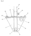
- Fig. 4 shows a suction head according to the invention in detail. 3 shows the casing of the hollow cone, 32 that of the inner tube connected to the suction hose and 30 that of the outer tube. The latter contains lateral suction holes 31 at the lower end, which are continued in the slots 4 of the conical jacket. In addition, the pipes are open towards the bottom. Fixing is possible by means of the set screw 33.
- Fig. 5 shows the lower area of a mobile, single-masted scaffold with a fork-shaped base 11 and a total of four roles.
- the two larger side rollers 41 are provided in pivotable roller bearings 43 and fastened to correspondingly elevated roller holders 44, while the two smaller, also pivotable rollers are attached to the underside of the fork tines in the end regions.
- the drawbar 45 is used for maneuvering the whole, while the rear stop 12 is, as said, an aid for positioning the container.
- 6 shows the left side of a quick-release fastener according to the invention with the retaining ring 6 for the flexible container wall 49. This is pulled over the protruding beads 46 and pressed by means of the stamp 47, which is actuated via the toggle lever 48. 50 represents the filling material.
- a single retaining ring is equipped with at least five such stamps and is preferably roughened in the region of its contact with the container wall.
- the procedure can be described as follows: In the starting position, the retaining ring 6 and the suction head 3 hang high, namely at the stop. After the container is positioned under the gallows. the suction head and the retaining ring are lowered, the suction head coming to rest on the material to be extracted. To lower the suction head (cable 1), one controls the pneumatic cylinder 14 by switching the 5/2-way valve 24 via the pressure regulator 23, while to lower the retaining ring (cable 2) the compressed air supply 27 to the pneumatic cylinder 15 by means of 5/2-way valve 51 switches from lifting to lowering. (The lowering speed is set by means of the vent throttle 21.) Now the operator puts the edge of the flexible container 49 over the holding ring and fixes it.
- the proposed bag emptying lotion with a suction device inserted from above has considerable advantages over the similar stations previously used: Since a pneumatic cylinder is provided for partial weight compensation of the suction head, its slow lowering can be jerky in the course of emptying, which has an advantageous effect on the suction process.
- the suction head according to the invention also contributes to an improvement in the suction effect or to a trouble-free sequence of the suction process, which, among other things, not only has a suction pipe that is open at the bottom, but also additionally has openings made on the side.
- the degree of automation of the system is increased by automatically switching on the vibrator in the suction head due to a corresponding sensor.
- the intended warning signal which is triggered by the bag holder when the stop is reached, also contributes to increasing the degree of automation. Overall, the system thus ensures largely trouble-free and automatic operation.
- changes to the scaffolding and bag holder are proposed that improve handling.
- the use of a single-mast, mobile gallows and a simple quick-release fastener for the bag suspension are particularly advantageous.
Landscapes
- Engineering & Computer Science (AREA)
- Mechanical Engineering (AREA)
- Basic Packing Technique (AREA)
- Control And Other Processes For Unpacking Of Materials (AREA)
- Making Paper Articles (AREA)
- Supplying Of Containers To The Packaging Station (AREA)
Abstract
Description
Ein derartiges Absaugverfahren wird in der OS DE 42 18 331 A1 vorgeschlagen, wobei das Absaugrohr an einer heb- und senkbaren Plattform befestigt, mit einem flexiblen Schlauch verbunden und am unteren Ende vorzugsweise mit einem Gitterkorb versehen ist, der das Ansaugen von Klumpen und Folien verhindert. Durch phosenverschobenes Betätigen der verschiedenen Plattform-Aufhängungsseile kann das Saugrohr zum Pendeln gebracht werden, was den Saugeffekt verbessert. Ferner ist ein Sensor vorgesehen, der zur Erkennung einer hinreichenden Annäherung an die jeweils oberste Lage des abzusaugenden Schüttgutes dient. Das Saugrohr kann auch teleskopierbar ausgebildet sein. Ausserdem ist ein Ventil für die Dosierung der Sekundärluft vorgesehen. Das zu entleerende Behältnis wird vorzugsweise mit mehreren Zugfedern an einem Traggestell stroffgezogen.
In der EPA 0 765 829 A1 sowie im Gebrauchsmuster DE 295 15 675 U1 wird ein verbessertes Saugrohr in Verbindung mit einem nach unten hin konisch verjüngten Saugkopf vorgeschlagen, welcher mit einem glockenförmigen Schwimmkörper sowie mit einer Schwingungsregelungseinrichtung versehen ist, wobei mit letzterer aber eher eine Schwingungserzeugzungseinrichtung In Form eines Vibrators gemeint ist. Durch den auf dem Schüttgut schwimmenden Schwimmkörper soll die Absaugöffnung in optimaler, horizontaler Lage gehalten und Insbesondere das Kippen des Saugrohres vermieden werden. Allerdings ist angesichts des relativ voluminösen Schwimmkörpers eine relativ große, im Sack verbleibende Restmenge zu erwarten.
In der OS DE 196 28 429 A1 sowie Im Gebrauchsmuster DE 296 12 187 U1 wird ferner eine Aufhängung des Sacks vorgeschlagen, welches mittels einer Hubeinrichtung in vertikaler Richtung bewegbar ist und zum Strecken des Sackes dient, wobei dessen oberer Rand von einem Hebezeug an drei Punkten gehalten wird. Eine derartige, den Sack straffende Aufhängung wird im folgenden «nachzügig» genannt. Als Hubeinrichtung kommt ein pneumatischer oder hydraulisch betätigter Hubzylinder, ein Elektroantrieb oder eine Handkurbel in Frage. Bei Einsatz eines pneumatischen Zylinders kann eine bestimmte, konstant nach oben ziehende Kraft vorgegeben werden. Infolge der Streckung rieselt das am Rand befindliche Schüttgut zur Mitte des Sackes hin, wo sich das Absaugrohr bzw. der Absaugkopf befindet, und kann so besser aufgenommen werden. Unterschreitet das Gewicht von Sack und Inhalt den der Zugkraft entsprechenden Wert, was gegen Ende des Entleerungsvorgangs der Fall ist, so wird das Ganze vom Boden abgehoben und der Sack noch stärker gegen unten zugespitzt, sodass eine fast restlose Entleerung möglich wird. Ausserdem zeigt das Hochheben des Sackes dem Betreiber an, dass der Vorgang seinem Ende zugeht und ein Sackwechsel eingeleitet werden kann. Ferner wird vorgeschlagen, die Endstellungen des Hubzylinders, d.h. die maximalen Ausfahr- und Einzugslängen der Kolbenstange, variabel einstellbar vorzusehen und somit an unterschiedliche Behältnishöhen anpassen zu können. Wie dies konkret zu bewerkstelligen ist, wird allerdings nicht näher erläutert. Insbesondere ist aber die Idee einer nachzügigen Aufhängung des Foliensacks bei einer Entleerung mittels eines von oben her eingeführten Saugrohres in der Beschreibung respektive Im Anspruch 15 der älteren, oben erwähnten EPA 0 765 829 A1 im wesentlichen bereits vorweggenommen. Auch die in der OS DE 42 18 331 A1 vorgesehenen Zugfedern zum Straffziehen der Behältniswand weisen in diese Richtung.
In der als Ergänzung zur obigen Idee gedachten OS DE 196 28 430 A1 sowie Im Gebrauchsmuster DE 296 12 1 85 U1 wird schliesslich vorgeschlagen, das Absaugrohr bzw. den Absaugkopf mit einer Gewichtsausgleichseinrichtung zu versehen, vorzugsweise In Form eines über einen Seilzug damit verbundenen Gegengewichts. Dabei wird dasselbe Prinzip angewandt, wie man es beispielsweise von Garagentoren her kennt. Indem jedoch das Gegengewicht etwas geringer eingestellt wird als das Gewicht des Absaugrohrs inklusive Absaugkopf, weisen letztere ein der Differenz entsprechendes Restgewicht auf. Dadurch wird erreicht, dass die - gewichfsabhängige - Eintauchtiefe des Saugrohres stets in einem bestimmten Bereich liegt. Ist jene nämlich zu gering, besteht die Gefahr, dass das Absaugrohr bzw. dessen Saugöffnung bei sinkendem Füllstand den Kontakt mit der Oberfläche des Füllgutes verliert und dass der Förderstrom deswegen abnimmt oder gar unterbrochen wird. Ist die Eintauchtiefe des Absaugrohres dagegen zu gross, besteht andererseits die Gefahr, dass wegen des zu hohen Drucks durch das Füllgut eine Verstopfung des Rohres eintritt. Überdies kann sich sonst das Absaugrohr unerwünschterweise auf den Grund des Sackes durchsaugen und dort die Folie ansaugen, wobei der Entleervorgang ebenfalls gestoppt wird. Die Bedienung der in der besagten Erfindung vorgesehenen Ausgleichsvorrichtung In der vorzugsweisen Form eines Gewichtszuges dürfte indessen spätestens dann ziemlich umständlich werden, wenn eine Anpassung an die Art des Schüttgutes erforderlich wird. Aber auch das Anheben des Saugkopfes im Anschluss an die Entleerung erfordert ein manuelles Eingreifen.
Der mit diesem ersten Seilzug verbundene pneumatische Zylinder wird dabei mit Vorteil von zwei wahlweise einschaltbaren Druckreglern angesteuert, wobei der eine, auf einen höheren Druck eingestellte Regler beim Heben des Saugkopfes - also nach erfolgter Entleerung des Behältnisses - und der andere, auf einen niedrigeren Druck eingestellte Regler als Gewichtskompensator beim Senken des Saugkopfes - also während der Entleerung des Behältnisses - In Aktion ist. Die Vorgabe dieser beiden an sich einstellbaren Druckwerte trägt zur Vereinfachung des Arbeitsablaufes bei. Da dieser erste, für das Heben und Senken des Saugkopfes zuständige Seilzug einen wesentlich längeren Weg als der zweite, für das Heben und Senken des Behältnisrandes zuständige Seilzug zurücklegen muss, wird er vorzugsweise mit einer Übersetzung versehen nach dem Prinzip eines Flaschenzugs.
Die vorzugsweise Ausführungsform besteht dabei wenigstens aus einem unterseitig offenen Rohr, einem konzentrisch dazu angeordneten, mit der Spitze nach unten weisenden Hohlkegel (Konus) sowie einem die Basis des Hohlkegels bildenden Deckel, Sowohl das Rohr als auch der Mantel des Hohlkegels sind in ihren unteren Bereichen mit Löchern perforiert, welche beim ersteren vorzugsweise rund sind und beim letzteren vorzugsweise eine In Vertikalrichtung längliche Form (Längsschlitze) aufweisen. Hierbei werden am besten drei bis fünf runde Löcher sowie acht Längsschlitze vorgesehen. Infolgedessen kann das Füllgut sowohl durch die untere Öffnung des Rohres als auch durch die seitlichen Löcher Im Kegel sowie anschliessend durch die seitlichen Löcher im Rohr aufgesaugt werden. Damit wird die Verstopfungsanfälligkeit des Saugkopfs vermindert. Zur Ermöglichung einer Falschluftzufuhr ist ein mit dem Absaugschlauch verbundenes Innenrohr In das Saugkopf-Rohr eingelassen und daran in gewünschter Lage fixierbar, und zwar derart, dass zwischen den beiden Rohren ein Spalt für von oben her einströmende Luft offen ist. Durch Veränderung der relativen Rohrlage ist zudem die Falschluftzufuhr auf einfache Weise verstellbar.
- Fig. 1
- eine stationäre Station (Seitenansicht);
- Fig. 2
- die Anordnung der beiden pneumatischen Zylinder (Sicht von hinten);
- Fig. 3
- das Schaltschema für die Druckregelung der pneumatischen Zylinder;
- Flg. 4
- die vorzugsweise Ausführungsform des Saugkopfes (Querschnitt);
- Fig. 5
- den Sockelbereich eines Gerüsts mit Rollen (perspektivische Sicht) und
- Fig. 6
- den Ausschnitt einer Halterung für das Behältnis (Querschnitt).
In Fig. 2 ist die Anordnung der beiden pneumatischen Zylinder im Mast dargestellt. Der pneumatische Zylinder 14 ist für das Heben und Senken des am Seilzug 1 befestigten Saugkopfes vorgesehen und bedarf wegen des erforderlichen langen Hubweges einer Übersetzung. Diese kommt durch einen Flaschenzug zustande, wobei einerseits frei drehbare Rollen 16 und andererseits eine Befestigung 17 am Seilende erforderlich sind. Für den mit dem pneumatischen Zylinder 15 verbundenen Seilzug 2, der für das Heben und Senken des Behältnisses zuständig ist, bedarf es dagegen keiner Übersetzung, weil der Hubweg relativ kurz ist. Von hinten sichtbar ist ausserdem der Absaugrohr-Bogen 18. Beide pneumatische Zylinder sind überdies unterseitig mit Druckausgleichsöffnungen 20 versehen. In Zylinder 15 ist ferner ein Magnetschalter 52 angebracht, mit dessen Hilfe automatisch der Warnblinker eingeschaltet wird, sobald der Kolben zum unteren Anschlag gelangt ist.
In Fig. 3 wird eine schematische Darstellung der für die beiden pneumatischen Zylinder erforderlichen Druckregler, Zuleitungen und Ventile gegeben. Die Druckluft-Zufuhr erfolgt darin aus der Richtung des Pfeils 28. Das Rückschlagventil 29 sorgt dafür, dass bei einer allfälligen Abschaltung der Zuleitung keine Luft zurückfliessen kann. 25 und 27 stellen die Druckluftleitungen von den Druckreglern 22, 23 und 26 zu den pneumatischen Zylindern 14 und 15 dar, welche mit den Enden der Seilzüge 1 bzw. 2 verbunden sind. Ferner sind die Kolben 19 in diesen Zylindern sowie die erforderlichen Druckausgleichsöffnungen 20 und der bereits erwähnte Magnetschalter 52 eingezeichnet.
Die für den pneumatischen Zylinder 14 zuständigen Druckregler 22 und 23 können über das 5/2-Weg-Ventil 24 wahlweise angesteuert werden: Entweder ist - wie in der Zeichnung hervorgehoben - der für die Gleichgewichtskompensation des Saugkopfes zuständige Druckregler 23 In Betrieb, oder aber - Im Falle des Weges über die gestrichelte Linie - der für das Heben des Saugkopfes zuständige Druckregler 22. Ersterer Ist auf einen geringeren Sollwert eingestellt als letzterer. Die Sollwerte hängen vom Gewicht des Saugkopfes bzw. von der gewünschten Eindringtiefe beim Füllgut ab. In der Praxis sind für die beiden Druckregler 22 und 23 Sollwerte von maximal fünf bar bzw. maximal drei bar angebracht.
Der für die Hebung des Behältnisses zuständige pneumatische Zylinder 15 bedarf dagegen nur eines einzigen Druckreglers 26, welcher über das 5/2-Weg-Ventil 51 angesteuert wird. Zur Entlüftung des Zylinders, also zur Absenkung der Behältnis-Halterung, dient die Drossel 21, welche auf einen gewünschten Wert einstellbar ist.
Fig. 4 zeigt einen erfindungsgemässen Saugkopf im Detail. 3 stellt dabei den Mantel des Hohlkegels dar, 32 denjenigen des mit dem Absaugschlauch verbundenen Innenrohrs und 30 denjenigen des Aussenrohrs. Letzteres enthält am unteren Ende seitliche Ansauglöcher 31, welche In den Schlitzen 4 des Kegelmantels ihre Fortsetzung finden. Ausserdem sind die Rohre gegen unten hin offen. Mittels der Stellschraube 33 ist eine Fixierung möglich. Die Falschluft wird über den Ringspalt 34 angesaugt und kann durch Verstellen der relativen Rohrposition beeinflusst werden. Ferner ist im Saugkopf ein Vibrator 38 mit einem Gegengewicht 39 sowie einem elektrischen Stecker 40 vorhanden. Der Deckel 35 ist unterseitig mit einer Gummidichtung versehen und oberseitig mit Schnellverschluss-Schrauben 36 sowie mit Befestigungs-Laschen 37.
Fig. 5 zeigt den unteren Bereich eines mobilen, einmastigen Gerüsts mit einem gabelförmigen Sockel 11 und Insgesamt vier Rollen. Dabei sind die zwei grösseren Seitenrollen 41 in schwenkbaren Rollenlagern 43 vorgesehen und an entsprechenden überhöhten Rollenhaltern 44 befestigt, während die zwei kleineren, ebenfalls schenkbaren Rollen In den Endbereichen der Gabel-Zinken an deren Unterseite angebracht sind. Der Deichsel 45 dient zum Manövrieren des Ganzen, während der hintere Anschlag 12 wie gesagt ein Hilfsmittel zur Positionierung des Behältnisses darstellt.
Fig. 6 zeigt die linke Seite eines erfindungsgemässen Schnellverschlusses mit dem Haltering 6 für die flexible Behältniswand 49. Diese wird über die vorstehenden Sicken 46 gezogen und mittels des Stempels 47 angepresst, welcher über den Kniehebel 48 betätigt wird. 50 stellt das Füllgut dar. Ein einzelner Haltering ist mit wenigstens fünf solcher Stempel ausgestattet und vorzugsweise im Bereich seines Kontakts mit der Behältniswand aufgerauht.
In der Ausgangsposition hangen der Haltering 6 wie auch der Saugkopf 3 hoch, und zwar im Anschlag. Nachdem das Behältnis unter dem Galgen positioniert ist. werden der Saugkopf wie auch der Haltering gesenkt, wobei der Saugkopf auf das abzusaugende Material zu liegen kommt. Zur Senkung des Saugkopfes (Seilzug 1) steuert man den pneumatischen Zylinder 14 durch Umschalten des 5/2-Weg-Ventils 24 über den Druckregler 23 an, während man zur Senkung des Halterings (Seilzug 2) die Druckluflzufuhr 27 zum pneumatischen Zylinder 15 mittels des 5/2-Weg-Ventils 51 von Heben auf Senken umschaltet. (Die Senkgeschwindigkeit wird mittels der Enlüftungsdrossel 21 eingestellt.) Nun stülpt der Betreiber den Rand des flexiblen Behältnisses 49 über den Haltering und fixiert ihn. Anschliessend lässt er den Haltering mittels des pneumatischen Zylinders 15 nach oben ziehen, indem er mittels des 5/2-Weg-Ventils 51 das Druckreduzierventil 26 bzw. die Druckluftzufuhr 27 einschaltet. Dadurch strafft sich die Behältniswand, ohne dass das Behältnis vom Boden abgehoben wird. Nach Einschalten des Saugers läuft der Entleerungsvorgang automatisch ab, wobei der Saugkopf immer weiter nach unten sinkt und die Behältnlswand immer weiter nach oben gezogen wird. Sobald der grösste Teil des Inhalts entleert ist, beginnt sich das Behältnis vom Boden abzuheben, wobei dessen Basis in der Mitte nach unten hängt. Währenddessen wird der Rest des Füllguts abgesaugt. Schliesslich gelangt das Behältnis bis zum oberen Anschlag, wobei automatisch der Magnetschalter 52 betätigt und damit der Warnblinker 13 eingeschaltet wird. Damit ist die Entleerung abgeschlossen. Der Betreiber muss nun durch Abschalten der Druckluftzufuhr 26 mittels des 5/2-Weg-Ventils 51 den Haltering für das Behältnis nach unten lassen und dieses daraufhin enffernen. Schliesslich werden durch Einschalten des Druckreglers 26 der Haltering sowie durch anschliessendes Einschalten des Druckreglers 22 der Saugkopf wieder nach oben gezogen und sind so für einen neuen Arbeitsgang bereit.
Indem zur teilweisen Gewichtskompensation des Saugkopfes ein pneumatischer Zylinder vorgesehen ist, kann dessen langsames Absenken Im Verlaufe der Entleerung ruckartig erfolgen, was sich vorteilhaft auf den Absaugvorgang auswirkt. Ebenfalls zu einer Verbesserung der Absaugwirkung bzw. zu einem störungsfreien Ablauf des Absaugvorgangs trägt der erfindungsgemässe Saugkopf bei, welcher u.a. nicht nur ein nach unten offenes Saugrohr aufweist, sondern zusätzlich noch seitlich angebrachte Öffnungen. Indem der im Saugkopf vorhandene Vibrator bei Unterdruck aufgrund eines entsprechenden Sensors automatisch eingeschaltet wird, erhöht sich der Automationsgrad der Anlage. Ebenfalls zur Erhöhung des Automationsgrades trägt das vorgesehene Warnsignal bei, welches von der Sackhalterung beim Erreichen des Anschlags ausgelöst wird. Insgesamt gewährleistet die Anlage also einen weitgehend störungsfreien und automatischen Betrieb. Darüberhinaus werden Veränderungen beim Traggerüst sowie bei der Sackhalterung vorgeschlagen, welche das Handling verbessern. Vorteilhaft sind dabei Insbesondere der Einsatz eines einmastigen, mobilen Galgens sowie eines einfachen Schnellverschlusses für die Sackaufhängung.
Claims (10)
- Vorrichtung zum Entleeren von rieselfähigem Schüttgut aus einem flexiblen, sackartigen Behältnis mittels eines von oben her eingeführten Saugers, wenigstens bestehend aus einem über einen Seilzug (1) und eine Kraft höhenverstellbaren, mit einem Vibrator versehenen Saugkopf (3), welcher in das Füllgut eintaucht und mit einem das Füllgut fördernden, einer Pumpe angeschlossenen Rohr (5) verbunden ist, wobei die nach oben ziehende Kraft während der Entleerung in etwa konstant ist und nahezu dem Eigengewicht des Saugkopfes entspricht, einer über einen anderen Seilzug (2) sowie einen pneumatischen Zylinder (15) ebenfalls, aber unabhängig vom ersten Seilzug höhenverstellbaren Halterung (6, 6') für das Behältnis, wobei die aufgrund des pneumatischen Zylinders nach oben ziehende Kraft während der Entleerung konstant ist bzw. vorgegeben werden kann und bei Unterschreiten eines Restgewichts das Behältnis vorzugsweise vom Boden abhebt, dadurch gekennzeichnet, dass
zur Erzeugung der den Saugkopf (3) nach oben ziehenden Kraft ein weiterer pneumatischer Zylinder (14) vorgesehen ist, welcher beim im Verlaufe der Entleerung erfolgenden langsamen Absenken des Saugkopfes vorzugsweise ruckartig reagiert. - Vorrichtung nach Anspruch 1, dadurch gekennzeichnet, dass der mit dem Seilzug (1) verbundene pneumatische Zylinder (14) von zwei wahlweise einschaltbaren Druckreglern (22,23) angesteuert wird, wobei der eine, auf einen höheren Druck eingestellte Regler beim Heben des Saugkopfes und der andere, auf einen niedrigeren Druck eingestellte Regler als Gewichtskompensator beim Senken des Saugkopfes, also während der Entleerung des Behältnisses, in Aktion ist.
- Vorrichtung nach wenigstens einem der Ansprüche 1 und 2, dadurch gekennzeichnet, dass der Seilzug (1) mit einer Übersetzung versehen ist nach dem Prinzip eines Flaschenzugs.
- Vorrichtung nach Anspruch 1, dadurch gekennzeichnet, dass der mit dem Seilzug (2) verbundene pneumatische Zylinder (15) einerseits von einem Druckregler (26) angesteuert wird, welcher die Einstellung eines gewünschten Restgewichts erlaubt, vorzugsweise eines Gewichts zwischen 60 und 100 kg, und dass er andererseits zur Entlüftung mit einer Drossel (21) versehen ist, womit ein Absenken der Behältnis-Halterung bzw. des Behältnisses, vorzugsweise nach erfolgter Entleerung möglich wird.
- Vorrichtung nach wenigstens einem der Ansprüche 1 und 4, dadurch gekennzeichnet, dass beim Erreichen des Anschlags des zweiten, für die Behältnis-Halterung zuständigen Seilzugs (2) automatisch ein Warnsignal erfolgt.
- Vorrichtung nach Anspruch 5, dadurch gekennzeichnet, dass zur Auslösung des Warnsignals bzw. zur Einschaltung des Blinklichts am unteren Ende des für das Heben des Behältnisses zuständigen pneumatischen Zylinders (15) ein Magnetschalter (52) vorgesehen ist, welcher vom Zylinderkolben beim Erreichen des Anschlags automatisch betätigt wird.
- Vorrichtung wenigstens nach einem der Ansprüche 1 bis 6, dadurch gekennzeichnet, dass der Saugkopf wenigstens aus einem unterseitig offenen Rohr (30), einem konzentrisch dazu angeordneten, mit der Spitze nach unten weisenden Hohlkegel sowie einem die Basis des Hohlkegels bildenden Deckel (35) besteht, und dass das Rohr in seinem unteren Bereich mit vorzugsweise runden Löchern (31) und der Hohlkegel unterseitig mit vorzugsweise in Vertikalrichtung länglichen Löchern perforiert ist, so dass das Schüttgut sowohl durch die untere Öffnung des Rohres als auch durch die seitlichen Löcher im Kegel sowie anschliessend durch die seitlichen Löcher im Rohr aufgesaugt werden kann.
- Vorrichtung nach Anspruch 7, dadurch gekennzeichnet, dass zur Ermöglichung einer Falschluftzufuhr ein mit dem Absaugschlauch verbundenes Innenrohr (32) in das Saugkopf-Rohr (30) eingelassen und daran in gewünschter Lage fixierbar ist, und zwar derart, dass zwischen den beiden Rohren ein Spalt (34) für von oben her einströmende Luft offen ist, wobei die Falschluftzufuhr durch Veränderung der relativen Rohrlage verstellbar ist.
- Vorrichtung nach wenigstens einem der Ansprüche 1 bis 8, dadurch gekennzeichnet, dass der Vibrator exzentrisch im Innern des Saugkopf-Kegels (3) angeordnet ist und dass zu dessen Ausbalancierung ein Gegengewicht (39) angebracht ist.
- Vorrichtung nach wenigstens einem der Ansprüche 7 bis 9, dadurch gekennzeichnet, dass der Vibrator, gesteuert über einen Drucksensor (7), während des Absaugvorgangs automatisch eingeschaltet wird.
Applications Claiming Priority (2)
| Application Number | Priority Date | Filing Date | Title |
|---|---|---|---|
| DE29803071U | 1998-02-23 | ||
| DE29803071U DE29803071U1 (de) | 1998-02-23 | 1998-02-23 | Automatisierte Sackentleerungsstation |
Publications (2)
| Publication Number | Publication Date |
|---|---|
| EP0943560A1 true EP0943560A1 (de) | 1999-09-22 |
| EP0943560B1 EP0943560B1 (de) | 2002-07-17 |
Family
ID=8053043
Family Applications (1)
| Application Number | Title | Priority Date | Filing Date |
|---|---|---|---|
| EP99810152A Expired - Lifetime EP0943560B1 (de) | 1998-02-23 | 1999-02-19 | Automatisierte Sackentleerungsstation |
Country Status (3)
| Country | Link |
|---|---|
| EP (1) | EP0943560B1 (de) |
| AT (1) | ATE220637T1 (de) |
| DE (1) | DE29803071U1 (de) |
Cited By (11)
| Publication number | Priority date | Publication date | Assignee | Title |
|---|---|---|---|---|
| WO2004103822A1 (en) * | 2003-05-15 | 2004-12-02 | Kellogg Company | Vacuum wand assembly for extracting a product from a container |
| DE202010000004U1 (de) | 2009-01-07 | 2010-05-06 | Varicolor Ag | Vorrichtung zum Entleeren von Schüttgut aus einem insbesondere sackartigen Behältnis |
| US7921624B2 (en) | 2008-06-05 | 2011-04-12 | Kellogg Company | Unitary transporter base and shaper and slip frame former for forming a transportable container |
| US8104520B2 (en) | 2008-06-11 | 2012-01-31 | Kellogg Company | Gentle handling hopper and scrunched bag for filling and forming a transportable container |
| US8191341B2 (en) | 2008-09-03 | 2012-06-05 | Kellogg Company | Method for forming a transportable container for bulk goods |
| WO2012131131A1 (es) * | 2011-04-01 | 2012-10-04 | Seppelec, S.L. | Máquina para el vaciado de bidones de forma automática e higiénica |
| CN105293094A (zh) * | 2015-11-19 | 2016-02-03 | 重庆钢铁(集团)有限责任公司 | 一种料场堆取料机供电用滑触线调整方法 |
| CN110498235A (zh) * | 2019-08-29 | 2019-11-26 | 西安西古光通信有限公司 | 一种护套料吸料装置及其使用方法 |
| CN115215108A (zh) * | 2022-08-30 | 2022-10-21 | 株洲时代新材料科技股份有限公司 | 一种空气弹簧检修线物料装卸方法及物料装卸装置 |
| CN115610788A (zh) * | 2022-10-20 | 2023-01-17 | 湖南宏工智能科技有限公司 | 一种用于吨袋的割袋装置 |
| CN116873310A (zh) * | 2023-09-07 | 2023-10-13 | 山西三强新能源科技有限公司 | 一种自动打包装置 |
Families Citing this family (4)
| Publication number | Priority date | Publication date | Assignee | Title |
|---|---|---|---|---|
| DE19852259C2 (de) * | 1998-11-13 | 2001-08-16 | Wilhelm Nikolaus | Entleervorrichtung für rieselfähiges Schüttgut |
| WO2012075228A2 (en) | 2010-12-01 | 2012-06-07 | Kellogg Company | Transportable container for bulk goods and method for forming the same |
| WO2015104427A1 (de) * | 2014-01-13 | 2015-07-16 | Hecht Technologie Gmbh | Entleerungsvorrichtung zur entleerung von behältern, insbesondere fässern, und entsprechendes saugrohr |
| DE202014011136U1 (de) | 2014-08-21 | 2018-01-25 | Siloanlagen Achberg Holding Gmbh | Sauglanze für die Absaugung von rieselfähigen Schüttgütern |
Citations (10)
| Publication number | Priority date | Publication date | Assignee | Title |
|---|---|---|---|---|
| DE624645C (de) | 1936-02-22 | Friedrich Endres | Silo fuer Getreide und aehnliches koerniges Schuettgut | |
| DE1531920A1 (de) | 1967-10-05 | 1970-01-15 | Eisgruber Karl Heinrich | Siloanlage |
| DE4218331A1 (de) | 1992-06-04 | 1993-12-09 | Bvb Baeckerei Und Silotechnolo | Vorrichtung und Verfahren zur Entleerung von Schüttgutbehältern |
| DE29515675U1 (de) | 1995-10-02 | 1995-11-30 | Fritz, Walter, 85232 Bergkirchen | Absaugvorrichtung für Schüttgutbehälter |
| DE29612185U1 (de) | 1996-07-15 | 1996-08-29 | Wilhelm, Klaus, 83022 Rosenheim | Absaugvorrichtung für Schüttgutbehälter |
| DE19506538A1 (de) * | 1995-02-24 | 1996-08-29 | Helmut Haas | Pulver-Entnahmevorrichtung |
| DE29612187U1 (de) | 1996-07-15 | 1996-08-29 | Wilhelm, Klaus, 83022 Rosenheim | Entleervorrichtung für rieselfähiges Schüttgut |
| DE19628430A1 (de) | 1996-07-15 | 1997-01-09 | Klaus Wilhelm | Absaugvorrichtung für Schüttgutbehälter |
| DE19628429A1 (de) | 1996-07-15 | 1997-01-16 | Klaus Wilhelm | Entleervorrichtung für rieselfähiges Schüttgut |
| EP0765829A1 (de) | 1995-10-02 | 1997-04-02 | Klaus Wilhelm | Absaugvorrichtung für Schüttgutbehälter |
-
1998
- 1998-02-23 DE DE29803071U patent/DE29803071U1/de not_active Expired - Lifetime
-
1999
- 1999-02-19 EP EP99810152A patent/EP0943560B1/de not_active Expired - Lifetime
- 1999-02-19 AT AT99810152T patent/ATE220637T1/de not_active IP Right Cessation
Patent Citations (10)
| Publication number | Priority date | Publication date | Assignee | Title |
|---|---|---|---|---|
| DE624645C (de) | 1936-02-22 | Friedrich Endres | Silo fuer Getreide und aehnliches koerniges Schuettgut | |
| DE1531920A1 (de) | 1967-10-05 | 1970-01-15 | Eisgruber Karl Heinrich | Siloanlage |
| DE4218331A1 (de) | 1992-06-04 | 1993-12-09 | Bvb Baeckerei Und Silotechnolo | Vorrichtung und Verfahren zur Entleerung von Schüttgutbehältern |
| DE19506538A1 (de) * | 1995-02-24 | 1996-08-29 | Helmut Haas | Pulver-Entnahmevorrichtung |
| DE29515675U1 (de) | 1995-10-02 | 1995-11-30 | Fritz, Walter, 85232 Bergkirchen | Absaugvorrichtung für Schüttgutbehälter |
| EP0765829A1 (de) | 1995-10-02 | 1997-04-02 | Klaus Wilhelm | Absaugvorrichtung für Schüttgutbehälter |
| DE29612185U1 (de) | 1996-07-15 | 1996-08-29 | Wilhelm, Klaus, 83022 Rosenheim | Absaugvorrichtung für Schüttgutbehälter |
| DE29612187U1 (de) | 1996-07-15 | 1996-08-29 | Wilhelm, Klaus, 83022 Rosenheim | Entleervorrichtung für rieselfähiges Schüttgut |
| DE19628430A1 (de) | 1996-07-15 | 1997-01-09 | Klaus Wilhelm | Absaugvorrichtung für Schüttgutbehälter |
| DE19628429A1 (de) | 1996-07-15 | 1997-01-16 | Klaus Wilhelm | Entleervorrichtung für rieselfähiges Schüttgut |
Cited By (15)
| Publication number | Priority date | Publication date | Assignee | Title |
|---|---|---|---|---|
| WO2004103822A1 (en) * | 2003-05-15 | 2004-12-02 | Kellogg Company | Vacuum wand assembly for extracting a product from a container |
| US6979166B2 (en) | 2003-05-15 | 2005-12-27 | Kellogg Company | Vacuum wand assembly for extracting a product from a container |
| US7921624B2 (en) | 2008-06-05 | 2011-04-12 | Kellogg Company | Unitary transporter base and shaper and slip frame former for forming a transportable container |
| US8104520B2 (en) | 2008-06-11 | 2012-01-31 | Kellogg Company | Gentle handling hopper and scrunched bag for filling and forming a transportable container |
| US8191341B2 (en) | 2008-09-03 | 2012-06-05 | Kellogg Company | Method for forming a transportable container for bulk goods |
| DE202010000004U1 (de) | 2009-01-07 | 2010-05-06 | Varicolor Ag | Vorrichtung zum Entleeren von Schüttgut aus einem insbesondere sackartigen Behältnis |
| WO2012131131A1 (es) * | 2011-04-01 | 2012-10-04 | Seppelec, S.L. | Máquina para el vaciado de bidones de forma automática e higiénica |
| ES2400553R1 (es) * | 2011-04-01 | 2013-05-17 | Seppelec S L | Maquinaria para el vaciado de bidones de forma automatica e higienica |
| CN105293094A (zh) * | 2015-11-19 | 2016-02-03 | 重庆钢铁(集团)有限责任公司 | 一种料场堆取料机供电用滑触线调整方法 |
| CN110498235A (zh) * | 2019-08-29 | 2019-11-26 | 西安西古光通信有限公司 | 一种护套料吸料装置及其使用方法 |
| CN115215108A (zh) * | 2022-08-30 | 2022-10-21 | 株洲时代新材料科技股份有限公司 | 一种空气弹簧检修线物料装卸方法及物料装卸装置 |
| CN115215108B (zh) * | 2022-08-30 | 2024-03-12 | 株洲时代新材料科技股份有限公司 | 一种空气弹簧检修线物料装卸方法及物料装卸装置 |
| CN115610788A (zh) * | 2022-10-20 | 2023-01-17 | 湖南宏工智能科技有限公司 | 一种用于吨袋的割袋装置 |
| CN116873310A (zh) * | 2023-09-07 | 2023-10-13 | 山西三强新能源科技有限公司 | 一种自动打包装置 |
| CN116873310B (zh) * | 2023-09-07 | 2023-11-17 | 山西三强新能源科技有限公司 | 一种自动打包装置 |
Also Published As
| Publication number | Publication date |
|---|---|
| EP0943560B1 (de) | 2002-07-17 |
| ATE220637T1 (de) | 2002-08-15 |
| DE29803071U1 (de) | 1998-05-20 |
Similar Documents
| Publication | Publication Date | Title |
|---|---|---|
| EP0819628B2 (de) | Verfahren zum Entleeren von Schüttgut | |
| EP0943560B1 (de) | Automatisierte Sackentleerungsstation | |
| DE2851184C2 (de) | Vorrichtung zum Füllen eines Behälters in staubfreiem Betrieb | |
| EP0765829B1 (de) | Absaugvorrichtung für Schüttgutbehälter | |
| EP2380813B1 (de) | Verfahren und Vorrichtung zum Entleeren von Schüttgut | |
| EP0188478A1 (de) | Vorrichtung zum befüllen flexibler schüttgutbehälter. | |
| DE2235747A1 (de) | Verfahren und vorrichtung zum verladen von schuettgut | |
| DE60210898T2 (de) | Beutelfüllvorrichtung | |
| EP1199266B1 (de) | Verfahren und Vorrichtung zum Entleeren von Schüttgut | |
| EP1580133B1 (de) | Verfahren und Vorrichtung zum Entleeren von Schüttgut | |
| DE7730505U1 (de) | Mobile entladevorrichtung fuer massengut | |
| DE102007021124A1 (de) | Entleervorrichtung für Big Bags (I) | |
| DE2701059A1 (de) | Vorrichtung zur bevorratung und befoerderung von gekoernten oder pulvrigen produkten | |
| DE19506538C2 (de) | Pulver-Entnahmevorrichtung | |
| DE4005968A1 (de) | Muellsammelfahrzeug | |
| DE202015105077U1 (de) | Füllstation zum Befüllen von flexiblen Großbehältern | |
| DE102010031769B4 (de) | Dosiervorrichtung für den Schüttgut-Inhalt von Großtaschen | |
| DE29803070U1 (de) | Saugkopf für Sackentleerungsvorrichtung | |
| DE20209351U1 (de) | Vorrichtung zum Handhaben von rieselfähigen Baustoffen | |
| DE29612187U1 (de) | Entleervorrichtung für rieselfähiges Schüttgut | |
| DE2635969C2 (de) | Fahrbarer Bandförderer | |
| DE69713045T2 (de) | Wägesystem und Methode zum Wägen eines in einen Transportbehälter, zum Beispiel einen grossen Sack, einzufüllendes Materials | |
| DE19628430A1 (de) | Absaugvorrichtung für Schüttgutbehälter | |
| DE3245821A1 (de) | Vorrichtung zum absaugen von sand, schlamm, erde und dergleichen | |
| DE29612185U1 (de) | Absaugvorrichtung für Schüttgutbehälter |
Legal Events
| Date | Code | Title | Description |
|---|---|---|---|
| PUAI | Public reference made under article 153(3) epc to a published international application that has entered the european phase |
Free format text: ORIGINAL CODE: 0009012 |
|
| AK | Designated contracting states |
Kind code of ref document: A1 Designated state(s): AT CH FR IT LI |
|
| AX | Request for extension of the european patent |
Free format text: AL;LT;LV;MK;RO;SI |
|
| 17P | Request for examination filed |
Effective date: 20000113 |
|
| AKX | Designation fees paid |
Free format text: AT CH FR IT LI |
|
| REG | Reference to a national code |
Ref country code: DE Ref legal event code: 8566 |
|
| 17Q | First examination report despatched |
Effective date: 20010228 |
|
| GRAG | Despatch of communication of intention to grant |
Free format text: ORIGINAL CODE: EPIDOS AGRA |
|
| GRAG | Despatch of communication of intention to grant |
Free format text: ORIGINAL CODE: EPIDOS AGRA |
|
| GRAH | Despatch of communication of intention to grant a patent |
Free format text: ORIGINAL CODE: EPIDOS IGRA |
|
| GRAH | Despatch of communication of intention to grant a patent |
Free format text: ORIGINAL CODE: EPIDOS IGRA |
|
| GRAA | (expected) grant |
Free format text: ORIGINAL CODE: 0009210 |
|
| AK | Designated contracting states |
Kind code of ref document: B1 Designated state(s): AT CH FR IT LI |
|
| PG25 | Lapsed in a contracting state [announced via postgrant information from national office to epo] |
Ref country code: IT Free format text: LAPSE BECAUSE OF FAILURE TO SUBMIT A TRANSLATION OF THE DESCRIPTION OR TO PAY THE FEE WITHIN THE PRESCRIBED TIME-LIMIT;WARNING: LAPSES OF ITALIAN PATENTS WITH EFFECTIVE DATE BEFORE 2007 MAY HAVE OCCURRED AT ANY TIME BEFORE 2007. THE CORRECT EFFECTIVE DATE MAY BE DIFFERENT FROM THE ONE RECORDED. Effective date: 20020717 Ref country code: FR Free format text: LAPSE BECAUSE OF NON-PAYMENT OF DUE FEES Effective date: 20020717 |
|
| REF | Corresponds to: |
Ref document number: 220637 Country of ref document: AT Date of ref document: 20020815 Kind code of ref document: T |
|
| REG | Reference to a national code |
Ref country code: CH Ref legal event code: EP |
|
| PGFP | Annual fee paid to national office [announced via postgrant information from national office to epo] |
Ref country code: CH Payment date: 20030127 Year of fee payment: 5 |
|
| EN | Fr: translation not filed | ||
| PG25 | Lapsed in a contracting state [announced via postgrant information from national office to epo] |
Ref country code: AT Free format text: LAPSE BECAUSE OF NON-PAYMENT OF DUE FEES Effective date: 20030219 |
|
| PLBE | No opposition filed within time limit |
Free format text: ORIGINAL CODE: 0009261 |
|
| STAA | Information on the status of an ep patent application or granted ep patent |
Free format text: STATUS: NO OPPOSITION FILED WITHIN TIME LIMIT |
|
| 26N | No opposition filed |
Effective date: 20030422 |
|
| PG25 | Lapsed in a contracting state [announced via postgrant information from national office to epo] |
Ref country code: LI Free format text: LAPSE BECAUSE OF NON-PAYMENT OF DUE FEES Effective date: 20040229 Ref country code: CH Free format text: LAPSE BECAUSE OF NON-PAYMENT OF DUE FEES Effective date: 20040229 |
|
| REG | Reference to a national code |
Ref country code: CH Ref legal event code: PL |