EP0944789B1 - Carter universel pour boites d'engrenage et groupes motoreducteurs a angle droit - Google Patents
Carter universel pour boites d'engrenage et groupes motoreducteurs a angle droit Download PDFInfo
- Publication number
- EP0944789B1 EP0944789B1 EP97927909A EP97927909A EP0944789B1 EP 0944789 B1 EP0944789 B1 EP 0944789B1 EP 97927909 A EP97927909 A EP 97927909A EP 97927909 A EP97927909 A EP 97927909A EP 0944789 B1 EP0944789 B1 EP 0944789B1
- Authority
- EP
- European Patent Office
- Prior art keywords
- housing
- output opening
- housing body
- universal mount
- integrated
- Prior art date
- Legal status (The legal status is an assumption and is not a legal conclusion. Google has not performed a legal analysis and makes no representation as to the accuracy of the status listed.)
- Expired - Lifetime
Links
- 238000010276 construction Methods 0.000 title abstract description 13
- 239000007787 solid Substances 0.000 abstract description 5
- 210000005069 ears Anatomy 0.000 description 9
- 239000003638 chemical reducing agent Substances 0.000 description 6
- 230000008901 benefit Effects 0.000 description 3
- 230000005540 biological transmission Effects 0.000 description 3
- 230000009286 beneficial effect Effects 0.000 description 2
- 238000004519 manufacturing process Methods 0.000 description 2
- 239000004610 Internal Lubricant Substances 0.000 description 1
- 230000001419 dependent effect Effects 0.000 description 1
- 239000011159 matrix material Substances 0.000 description 1
- 238000012986 modification Methods 0.000 description 1
- 230000004048 modification Effects 0.000 description 1
Images




Classifications
-
- F—MECHANICAL ENGINEERING; LIGHTING; HEATING; WEAPONS; BLASTING
- F16—ENGINEERING ELEMENTS AND UNITS; GENERAL MEASURES FOR PRODUCING AND MAINTAINING EFFECTIVE FUNCTIONING OF MACHINES OR INSTALLATIONS; THERMAL INSULATION IN GENERAL
- F16H—GEARING
- F16H57/00—General details of gearing
- F16H57/02—Gearboxes; Mounting gearing therein
- F16H57/031—Gearboxes; Mounting gearing therein characterised by covers or lids for gearboxes
-
- F—MECHANICAL ENGINEERING; LIGHTING; HEATING; WEAPONS; BLASTING
- F16—ENGINEERING ELEMENTS AND UNITS; GENERAL MEASURES FOR PRODUCING AND MAINTAINING EFFECTIVE FUNCTIONING OF MACHINES OR INSTALLATIONS; THERMAL INSULATION IN GENERAL
- F16H—GEARING
- F16H57/00—General details of gearing
- F16H57/02—Gearboxes; Mounting gearing therein
- F16H57/025—Support of gearboxes, e.g. torque arms, or attachment to other devices
-
- F—MECHANICAL ENGINEERING; LIGHTING; HEATING; WEAPONS; BLASTING
- F16—ENGINEERING ELEMENTS AND UNITS; GENERAL MEASURES FOR PRODUCING AND MAINTAINING EFFECTIVE FUNCTIONING OF MACHINES OR INSTALLATIONS; THERMAL INSULATION IN GENERAL
- F16H—GEARING
- F16H57/00—General details of gearing
- F16H57/02—Gearboxes; Mounting gearing therein
-
- F—MECHANICAL ENGINEERING; LIGHTING; HEATING; WEAPONS; BLASTING
- F16—ENGINEERING ELEMENTS AND UNITS; GENERAL MEASURES FOR PRODUCING AND MAINTAINING EFFECTIVE FUNCTIONING OF MACHINES OR INSTALLATIONS; THERMAL INSULATION IN GENERAL
- F16H—GEARING
- F16H57/00—General details of gearing
- F16H57/02—Gearboxes; Mounting gearing therein
- F16H57/033—Series gearboxes, e.g. gearboxes based on the same design being available in different sizes or gearboxes using a combination of several standardised units
-
- Y—GENERAL TAGGING OF NEW TECHNOLOGICAL DEVELOPMENTS; GENERAL TAGGING OF CROSS-SECTIONAL TECHNOLOGIES SPANNING OVER SEVERAL SECTIONS OF THE IPC; TECHNICAL SUBJECTS COVERED BY FORMER USPC CROSS-REFERENCE ART COLLECTIONS [XRACs] AND DIGESTS
- Y10—TECHNICAL SUBJECTS COVERED BY FORMER USPC
- Y10T—TECHNICAL SUBJECTS COVERED BY FORMER US CLASSIFICATION
- Y10T74/00—Machine element or mechanism
- Y10T74/21—Elements
- Y10T74/2186—Gear casings
Definitions
- the present invention relates generally to general purpose and industrial power transmission devices corresponding to the preamble of claim 1 and, in particular, to a novel housing construction for gearboxes and gearmotors in the right angle configuration.
- the right angle housing concept described herein will allow the coverage of practically all industry standard mountings with one universal housing.
- Gearboxes and gearmotors with right angle power transmission flow are widely used as preferred drive configurations in numerous industrial drive applications.
- To achieve a right angle power transmission flow primarily worm, bevel and hypoid gear configurations are utilized throughout the industry.
- gearbox series frequently utilize combinations of a standardized modular gear set system (as the ratio sensitive portion) with a right angle stage.
- standardized modular gear configuration systems are most commonly based on a spur or helical pinion and wheel combination matrix, or on other gear systems able to cover a large ratio change, such as the CYCLO® system manufactured by Sumitomo Machinery Corp. of America.
- the housing of the gearboxes and gearmotors needs to be connected to the driven machinery.
- the connection must give adequate support primarily for the reaction torque but also for the weight forces as well as, in many applications, for the axial and radial forces from the driven machinery.
- the housing design needs also to provide good multiplanar alignment of the driving and driven shafts relative to each other.
- a speed reducer comprising a casing for gearing, a removable side-plate and a lateral lid connected to said casing.
- the casing has opposite to the side-plate a large surface.
- the side-plate and the surface having a series of bores for journaling a gear shaft, each bore of said surface being of equal size with, disposed opposite, and in registry with, a bore in said side-plate and forming therewith a pair, the number of pairs of bores being equal to the largest number of sets of gears operable in said casing plus one.
- the casing presents on approximately prismatic shape, which is very characteristic with speed reducers.
- reducers comprising cylindrical gears with parallel input and output shafts
- reducers comprising bevel and cylindrical gears with shafts at right angles
- monobloc reducers I.e. designed to receive flanged motors and to constitute with the latter complete units.
- US 3,521,503 describes a gear housing of substantially rectangular shape having six boundary surfaces perpendicular to each other. Recesses are provided into oppositely facing surfaces and are bounded at their edges by flange-like projecting edge parts. The flange-like projecting edge parts have slots therein, open at one end for the introduction of fixing screws.
- the housing has at least two through bores or slots open at one end and which are perpendicular to the two oppositely facing boundary surfaces for receiving mounting screws.
- a universal mount housing construction for parallel offset gearboxes that allows a wide variety of mounting and torque support configurations.
- the housing construction includes a generally cubic-shaped housing body having an input opening for receiving a rotational power input and at least one output opening for transmitting a rotational power output, the output opening having a central axis which is perpendicular to a central axis of the input opening.
- a plurality of integrated raised feet are provided on three sides of the housing body, including a side of the housing body opposite to the input opening and perpendicular to the central axis of the input opening, and both sides of the housing body which are in planes parallel to both of the central axes of the input and output openings.
- the raised feet each have a tapped bore formed therein.
- the tapped bores preferably provide an identical bolt hole pattern on each of the three sides of the housing body.
- a pair of integrated, plate-shaped housing extensions are formed on two sides of the housing body which extend in two respective planes perpendicular to the central axis of the output opening.
- Each of the housing extensions provide an integrated torque arm having a through-bore formed therein for attachment purposes.
- a raised, machined surface is formed in the housing body around the output opening and extends to the plate-shaped housing extensions.
- the raised, machined surface provides a flat attachment surface.
- a centering bore is formed in the housing body concentric with the output opening, the centering bore providing, together with the through-bores in the plate-shaped housing extensions and the flat attachment surface, a flange type attachment.
- a set of tapped bores is provided in the housing body around the output opening for attaching an add-on flange arrangement.
- the present invention features a universal mount housing construction for right angle gearboxes and gearmotors which allows a wide variety of mounting and torque support configurations, including all of the mounting and torque arm configurations described above. This is accomplished by the integrated or "designed in” features of the housing and, in some cases, by using standard added hardware, such as brackets, bolt-on feet, and so forth.
- the housing design approach presented here gives exceptional flexibility to the industrial gearbox/gearmotor user. At the same time, production and global inventory costs are reduced due to high volume manufacturing and subsequent stocking of only a single kind of universal housing, as described herein.
- Figure 1 provides a perspective view of a right angle gearbox 20 having a universal mount housing according to a first embodiment of the present invention.
- the right angle gearbox 20 uses a worm gear as the right angle stage. Consequently, the center lines of the input shaft 1 and the output shaft 2 are at a right angle offset configuration.
- the input can be a free standing input shaft 1, as depicted in Figure 1, or integrated with a motor to form an integral gearmotor unit. Furthermore, the input can be combined with a primary gear stage, which can be of a helical, spur, planetary, or cycloidal type, or any other gear system. As shown in Figure 1, an input opening having a central axis Ri is provided in the body of the housing concentric with the input shaft 1 for receiving a rotational driving force into the housing.
- An output opening is provided in the body of the housing for transmitting a rotational force from the housing through the output shaft 2.
- the output opening of the housing has a central axis Ro, as shown in Figure 1.
- the output shaft 2 can be of a hollow or solid shaft type.
- the housing of the gearbox 20 maintains a cubic-shaped design with integrated sets of flat machined feet 3a, 3b, 3c at the three major mounting sides of the body of the housing.
- the feet 3a, 3b, 3c have tapped bores 4, which provide easy attachment of the gearbox 20 to the structure of the driven machinery.
- the flat machined feet 3a, 3b, 3c with the tapped bores 4 also provide an ideal attachment base for a variety of mounting brackets, base plates, torque arms, and other mounting hardware.
- the housing has two sets of ears 5a and 5b with bores 6 which function as torque arm attachment locations.
- the torque arm attachment ears 5a and 5b are used primarily for hollow shaft mount units.
- Raised machined surfaces 7 are provided on both output side faces of the body of the housing.
- the raised machined surfaces 7 extend around the output shaft housing bore 9 over to both ears 5a, 5b. These machined surfaces 7 around the output shaft housing bore 9 provide ideal surfaces for mounting the gearbox or gearmotor to a surface which is perpendicular to the center line of the output shaft 2.
- the output shaft housing bore 9 is designed in such a way as to allow the engagement of a male type centering pilot.
- the two smaller attachment bores 6 at the torque arm ears 5a, 5b, together with the above-described output shaft housing bore 9 and pilot, provide the three necessary alignment and supporting points to allow the gearbox to be directly and simply bolted to the structure of the driven machinery. This arrangement serves as an integrated flange directly in the housing, thereby providing significant savings in mounting space.
- the machined surface around the shaft housing bores 9 features a set of appropriately spaced, tapped bores 8 for easy attachment of a traditional round flange.
- the above-described centering pilot acts to secure the flange with the universal housing and provide proper alignment.
- the assembly of the internal components of the gearbox is accomplished through a top cover 10, as well as through the bores for the input and output shafts 1, 2.
- the top cover 10 is designed to have its top surface below the mounting surfaces of the feet 3a.
- all of the mounting feet 3a, 3b, 3c are integral with the housing structure and provide the sole attachment surfaces for the housing structure. Consequently, the top cover 10 is not subjected to any external reaction or internal gearing forces. Thus, the housing structure is better protected against leakage of any type of internal lubricant.
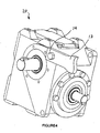
- Figure 2 shows a right angle gearbox 30 having a housing configuration according to a second embodiment of the present invention.
- the right angle gearbox 30 utilizes bevel gears as the right angle gear stage.
- the housing configuration according to the second embodiment incorporates basically the same beneficial features found in the first embodiment, as described above.
- the primary difference is that the cover of the housing according to the second embodiment is opposite the input side of the gearbox.
- the centerlines of the input and output shafts 1', 2' are intersecting and not offset like in the worm gear type unit of the first embodiment shown in Figure 1.
- the housing of the gearbox 30 has a cubic-shaped design with integrated pairs of parallel, flat machined feet 3a', 3b', 3c' at the three major mounting sides of the housing.
- the feet 3a', 3b', 3c' have tapped bores 4', which provide easy attachment of the gearbox 30 to the structure of the driven machinery.
- the flat machined feet 3a', 3b', 3c' with the tapped bores 4' also provide an ideal attachment base for a variety of mounting brackets, base plates, torque arms, and other mounting hardware.
- the housing of the gearbox 30 has two sets of ears 5a' and 5b' with bores 6' which function as torque arm attachment locations.
- Raised, machined surfaces 7' are provided on both output side faces of the housing of the gearbox 30 around the output shaft housing bore 9' over to both ears 5a', 5b'.
- FIG 3 shows the right angle gearbox 20 according to the first embodiment of the present invention, with a turn buckle type torque arm 11 attached to one of the integrated torque arm ears 5a.
- the torque arm 11 has a turn buckle 12 that extends through the bore 6 of the integrated torque arm ear 5a.
- the integrated torque arm ear 5a thereby allows an easy attachment of the turn buckle type torque arm 11, without the need to remove housing bolts as is commonly done on conventional housing designs.
- FIG. 4 shows the right angle gearbox 20 according to the first embodiment of the present invention, with a torque arm mounting arrangement utilizing a simple extension plate 13 of the driven machinery structure attached to one of the integrated torque arm ears 5a by a simple bolt or pin 14. This provides a very compact mounting.
- Figure 5 shows a torque arm arrangement 15 attached to the feet 3a at one side of the universal mount gearbox housing.
- the same bolt hole pattern is preferably provided for all three sets of mounting feet 3a, 3b, 3c so that the same torque arm arrangement 15 can be mounted on any of the three mounting surfaces of the housing. This further increases the flexibility of the universal mount housing without requiring additional mechanical attachment devices.
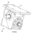
- Figure 6 depicts the attachment of a mounting plate 16 to the universal mount housing (or the universal mount housing to a base plate).
- the mounting plate 16 utilizes the tapped bores 4 on the integrated feet 3a.
- the same mounting plate 16 can be used on all three mounting surfaces of the housing by providing the same bolt hole pattern for the integrated feet 3a on all sides.
- Figure 7 shows a mounting configuration where the driving structure is attached directly to the driven structure 17 by utilizing the raised, machined surface 7 at the output side of the gearbox 20 along with the three defined attachment points; namely the centering pilot/bore contact and two bolts mounted through the bores 6 in the integrated torque arm ears 5b.
Landscapes
- Engineering & Computer Science (AREA)
- General Engineering & Computer Science (AREA)
- Mechanical Engineering (AREA)
- General Details Of Gearings (AREA)
- Gear Transmission (AREA)
- Motor Power Transmission Devices (AREA)
- Harvester Elements (AREA)
- Soil Working Implements (AREA)
- Retarders (AREA)
- Connection Of Motors, Electrical Generators, Mechanical Devices, And The Like (AREA)
Claims (13)
- Carter de montage universel pour boíte d'engrenage (20, 30) à angle droit, comprenant :caractérisé par au moins une extension de carter intégrée en forme de plaque (5a, 5b ; 5a', 5b') fournissant un bras de couple intégré formé sur une face du corps de carter s'étendant dans un plan perpendiculaire à l'axe central (Ro) de la première ouverture de sortie (9 ; 9'), l'extension de carter comprenant un trou débouchant (6 ; 6') formé dans celle-ci ; et l'extension de carter comprenant une surface qui est sensiblement coplanaire à la surface de fixation plate.un corps de carter de forme générale cubique ayant une ouverture d'entrée pour recevoir une entrée de puissance rotative (1) et au moins une première ouverture de sortie (9 ; 9') pour transmettre une sortie de puissance rotative, la première ouverture de sortie (9 ; 9') ayant un axe central (Ro) qui est perpendiculaire à un axe central (Ri) de l'ouverture d'entrée ; etplusieurs pieds intégrés en saillie (3a, 3b, 3c ; 3a', 3b', 3c') prévus sur trois faces du corps de carter, les trois faces du corps de carter comprenant une face du corps de carter opposée à l'ouverture d'entrée et perpendiculaire à l'axe central (Ri) de l'ouverture d'entrée, et deux faces du corps de carter qui sont dans des plans parallèles aux deux axes centraux (Ri, Ro) des ouvertures d'entrée et de sortie ; etune surface de fixation plate (7 ; 7') formée sur le corps de carter autour de la première ouverture de sortie (9 ; 9'),
- Carter de montage universel selon la revendication 1, dans lequel les pieds en saillie (3a, 3b, 3c ; 3a', 3b', 3c') ont chacun un trou taraudé formé dans ceux-ci.
- Carter de montage universel selon la revendication 2, dans lequel les trous taraudés (4 ; 4') forment un motif de trou de vis identique sur chacune des trois faces du corps de carter.
- Carter de montage universel selon l'une des revendications précédentes, dans lequel la au moins une extension de carter comprend deux extensions de carter intégrées en forme de plaque (5a, 5b ; 5a', 5b') formées sur deux faces du corps de carter, les deux faces du corps de carter s'étendant dans deux plans respectifs qui sont perpendiculaires à l'axe central (Ro) de la première ouverture de sortie (9 ; 9').
- Carter de montage universel selon la revendication 4, dans lequel chaque extension de carter (5a, 5b ; 5a', 5b') fournit un bras de couple intégré ayant un trou débouchant (6 ; 6') formé dans celui-ci à des fins de fixation, chaque trou débouchant (6 ; 6') s'étendant au travers de l'une des extensions de carter respectives dans une direction parallèle à l'axe central de la première ouverture de sortie (9 ; 9').
- Carter de montage universel selon l'une des revendications précédentes, dans lequel la surface de fixation plate comprend une surface usinée en saillie (7 ; 7') formée dans le corps de carter autour de la première ouverture de sortie (9 ; 9') et s'étendant jusqu'aux extensions de carter en forme de plaque (5a, 5b ; 5a', 5b').
- Carter de montage universel selon la revendication 6, comprenant en outre un trou de centrage formé dans le corps de carter de façon concentrique avec la première ouverture de sortie (9 ; 9'), le trou de centrage formant, avec les trous débouchants (6 ; 6') dans les extensions de carter en forme de plaque (5a, 5b ; 5a', 5b') et la surface de fixation plate (7 ; 7'), une liaison à bride.
- Carter de montage universel selon l'une des revendications précédentes, comprenant en outre un ensemble de trous taraudés (8 ; 8') formés dans le corps de carter autour de la première ouverture de sortie (9 ; 9').
- Carter de montage universel selon la revendication 1, dans lequel la au moins une extension de carter comprend une première paire d'extensions de carter intégrées en forme de plaque (5a ; 5a') formées sur la face du corps de carter qui est perpendiculaire à l'axe central (Ro) de la première ouverture de sortie (9 ; 9'), chaque extension de carter fournissant un bras de couple intégré ayant un trou débouchant (6 ; 6') formé dans celui-ci à des fins de fixation ; et
dans lequel la surface de fixation comprend une surface intégrée en saillie (7 ; 7') formée dans le corps de carter autour de la première ouverture de sortie (9 ; 9') et s'étendant jusqu'aux extensions de carter en forme de plaque (5a ; 5a'), la surface en saillie formant une première surface de fixation plate, et un ensemble de trous taraudés (8 ; 8') prévus dans la surface en saillie (7 ; 7') du corps de carter autour de l'ouverture de sortie (9 ; 9'). - Carter de montage universel selon la revendication 9, dans lequel le corps de carter comprend en outre une seconde ouverture de sortie formée dans une face du corps de carter opposée à la première ouverture de sortie, la seconde ouverture de sortie étant coaxiale à la première ouverture de sortie (9 ; 9').
- Carter de montage universel selon les revendications 9 ou 10, dans lequel les trous débouchants (6 ; 6') formés dans chaque extension de carter s'étendent dans une direction parallèle à l'axe central de la première ouverture de sortie (9 ; 9').
- Carter de montage universel selon la revendication 1, dans lequel le trou débouchant s'étend au travers de la au moins une extension de carter dans une direction parallèle à l'axe central de la première ouverture de sortie (9 ; 9').
- Carter de montage universel selon la revendication 12, comprenant en outre un ensemble de trous taraudés (8 ; 8'), prévus dans la surface de fixation plate (7 ; 7') du corps de carter autour de l'ouverture de sortie.
Applications Claiming Priority (3)
| Application Number | Priority Date | Filing Date | Title |
|---|---|---|---|
| US6989396P | 1996-12-13 | 1996-12-13 | |
| US69893P | 1996-12-13 | ||
| PCT/US1997/009456 WO1998026201A1 (fr) | 1996-12-13 | 1997-05-28 | Carter universel pour boites d'engrenage et groupes motoreducteurs a angle droit |
Publications (3)
| Publication Number | Publication Date |
|---|---|
| EP0944789A1 EP0944789A1 (fr) | 1999-09-29 |
| EP0944789A4 EP0944789A4 (fr) | 1999-12-15 |
| EP0944789B1 true EP0944789B1 (fr) | 2004-03-17 |
Family
ID=22091854
Family Applications (1)
| Application Number | Title | Priority Date | Filing Date |
|---|---|---|---|
| EP97927909A Expired - Lifetime EP0944789B1 (fr) | 1996-12-13 | 1997-05-28 | Carter universel pour boites d'engrenage et groupes motoreducteurs a angle droit |
Country Status (9)
| Country | Link |
|---|---|
| US (1) | US5816116A (fr) |
| EP (1) | EP0944789B1 (fr) |
| JP (1) | JP3832861B2 (fr) |
| KR (1) | KR20000035994A (fr) |
| CN (1) | CN1078940C (fr) |
| AT (1) | ATE262124T1 (fr) |
| AU (1) | AU3225697A (fr) |
| DE (1) | DE69728161T2 (fr) |
| WO (1) | WO1998026201A1 (fr) |
Cited By (1)
| Publication number | Priority date | Publication date | Assignee | Title |
|---|---|---|---|---|
| US8474347B2 (en) | 2009-06-08 | 2013-07-02 | Hub City, Inc. | High efficiency right angle gearbox |
Families Citing this family (23)
| Publication number | Priority date | Publication date | Assignee | Title |
|---|---|---|---|---|
| JP4757983B2 (ja) * | 2000-07-07 | 2011-08-24 | 住友重機械工業株式会社 | 分離型歯車箱、及び、半割箱鋳造用鋳型 |
| DE10135602B4 (de) * | 2001-07-21 | 2005-05-25 | Getriebebau Nord Gmbh & Co. Kg | Baukastengetriebe |
| TWI223036B (en) * | 2002-03-22 | 2004-11-01 | Sumitomo Heavy Industries | Speed reduction device for gear reduction motor, gear reduction motor and products thereof |
| US6912927B2 (en) * | 2002-05-15 | 2005-07-05 | Reliance Electric Technologies, Llc | Modular-flexible wormshaft assembly |
| DE10234749A1 (de) | 2002-07-30 | 2004-02-26 | Wittenstein Ag | Kegelradgetriebe, insbesondere Hypoidgetriebe |
| US20050066756A1 (en) * | 2003-09-30 | 2005-03-31 | Clare Patrick S. | System for securing a motor transversely to a gearbox |
| US7273132B2 (en) * | 2003-10-15 | 2007-09-25 | Weasler Engineering, Inc. | Method and apparatus for lubricating bearings on a vertical shaft in a gearbox |
| DE102004055743B4 (de) * | 2004-02-12 | 2012-02-02 | Sew-Eurodrive Gmbh & Co. Kg | Ein- oder mehrstufiges Planetengetriebe und Bausatz |
| KR100548009B1 (ko) * | 2004-05-22 | 2006-02-01 | 삼성테크윈 주식회사 | 동력 전달 장치 |
| DE102004030180A1 (de) * | 2004-06-22 | 2006-02-09 | A. Friedr. Flender Ag | Stirnradgetriebe |
| DE102004038581A1 (de) * | 2004-08-06 | 2006-02-23 | Wittenstein Ag | Kegelradgetriebe |
| US8770063B2 (en) * | 2007-04-30 | 2014-07-08 | Robert Bosch Gmbh | Gearbox housing assembly |
| WO2012037017A2 (fr) * | 2010-09-13 | 2012-03-22 | Illinois Tool Works Inc. | Ensemble pétrin mécanique horizontal avec configuration de train réducteur multiple pour basculement du bol |
| DE102013012718B4 (de) * | 2013-08-01 | 2025-11-20 | Sew-Eurodrive Gmbh & Co Kg | Getriebe mit einem Gehäuseteil |
| US9377097B2 (en) * | 2014-02-21 | 2016-06-28 | Kuhn North America, Inc. | Cartridge drive |
| JP6201878B2 (ja) | 2014-04-30 | 2017-09-27 | スズキ株式会社 | トランスミッション |
| CN104019337B (zh) * | 2014-05-23 | 2016-01-13 | 郑州机械研究所 | 能够实现高刚度回转中心正交的双转轴机构 |
| DE102015211183A1 (de) * | 2015-06-18 | 2016-12-22 | Voith Patent Gmbh | Getriebegehäuse für ein Fahrzeuggetriebe |
| US9551412B1 (en) * | 2015-08-14 | 2017-01-24 | JD Components, LLC | Gearboxes and related assemblies |
| US10487975B2 (en) * | 2016-12-21 | 2019-11-26 | Bradley Ray Smith | Rotational coupling device |
| JP2020016253A (ja) * | 2018-07-23 | 2020-01-30 | オリエンタルモーター株式会社 | 直交軸歯車減速機 |
| US11859399B2 (en) * | 2021-04-30 | 2024-01-02 | Nez Khan, L.L.C. | Adaptable fence bracing |
| FR3163908A1 (fr) * | 2024-06-26 | 2026-01-02 | Stellantis Auto Sas | Reducteur adaptable a de multiples configurations de vehicules electriques ou hybrides |
Family Cites Families (9)
| Publication number | Priority date | Publication date | Assignee | Title |
|---|---|---|---|---|
| US2734393A (en) * | 1956-02-14 | ujenberger | ||
| US1246930A (en) * | 1917-02-14 | 1917-11-20 | Arthur E Jenney | Adaptable motor and mounting. |
| BE491931A (fr) * | 1949-10-31 | |||
| AT271123B (de) * | 1967-06-15 | 1969-05-27 | Helmut Joerg | Getriebegehäuse |
| AT345051B (de) * | 1974-08-07 | 1978-08-25 | Louis Joerg Ges M B H | Einrichtung zum kuehlen eines schmiermittelgefuellten, mit kuehlrippen versehenen getriebegehaeuses mittels eines angebauten ventilators |
| JPS6044663A (ja) * | 1983-08-19 | 1985-03-09 | Tsubakimoto Moorusu:Kk | ケ−シング |
| JPH0741962Y2 (ja) * | 1988-07-29 | 1995-09-27 | 三菱重工業株式会社 | 多面据付形減速機 |
| AT413054B (de) * | 1992-05-04 | 2005-10-15 | Joerg Helmut | Getriebegehäuse |
| JPH0644663A (ja) * | 1992-07-27 | 1994-02-18 | Sony Corp | ローディング装置 |
-
1997
- 1997-05-28 EP EP97927909A patent/EP0944789B1/fr not_active Expired - Lifetime
- 1997-05-28 KR KR1019990701947A patent/KR20000035994A/ko not_active Withdrawn
- 1997-05-28 AT AT97927909T patent/ATE262124T1/de not_active IP Right Cessation
- 1997-05-28 AU AU32256/97A patent/AU3225697A/en not_active Abandoned
- 1997-05-28 WO PCT/US1997/009456 patent/WO1998026201A1/fr not_active Ceased
- 1997-05-28 DE DE69728161T patent/DE69728161T2/de not_active Expired - Lifetime
- 1997-05-28 JP JP52661298A patent/JP3832861B2/ja not_active Expired - Fee Related
- 1997-05-28 US US08/864,380 patent/US5816116A/en not_active Expired - Fee Related
- 1997-05-28 CN CN97197858A patent/CN1078940C/zh not_active Expired - Lifetime
Cited By (1)
| Publication number | Priority date | Publication date | Assignee | Title |
|---|---|---|---|---|
| US8474347B2 (en) | 2009-06-08 | 2013-07-02 | Hub City, Inc. | High efficiency right angle gearbox |
Also Published As
| Publication number | Publication date |
|---|---|
| JP2001505985A (ja) | 2001-05-08 |
| US5816116A (en) | 1998-10-06 |
| CN1078940C (zh) | 2002-02-06 |
| ATE262124T1 (de) | 2004-04-15 |
| JP3832861B2 (ja) | 2006-10-11 |
| DE69728161D1 (de) | 2004-04-22 |
| EP0944789A1 (fr) | 1999-09-29 |
| CN1230247A (zh) | 1999-09-29 |
| AU3225697A (en) | 1998-07-03 |
| KR20000035994A (ko) | 2000-06-26 |
| DE69728161T2 (de) | 2004-11-25 |
| EP0944789A4 (fr) | 1999-12-15 |
| WO1998026201A1 (fr) | 1998-06-18 |
Similar Documents
| Publication | Publication Date | Title |
|---|---|---|
| EP0944789B1 (fr) | Carter universel pour boites d'engrenage et groupes motoreducteurs a angle droit | |
| EP0677416B1 (fr) | Chapeau de palier et bride de montage d'une pompe pour unité de prise de force | |
| KR930002623B1 (ko) | 산업용 로보트의 손목조립체 | |
| EP0497354B1 (fr) | Engrenage rectangulaire avec moteur | |
| EP0632213B1 (fr) | Boîte de vitesse angulaire avec plusieurs étages de réduction | |
| US6125717A (en) | Close-connected shaft adapter assembly, jack shaft assembly, and power transmission assembly using same | |
| CN100385776C (zh) | 齿轮传动马达 | |
| US10377037B2 (en) | Speed reduction device, join servo and robot | |
| US6029532A (en) | Gearing commonality system for gear reducers | |
| US7225698B2 (en) | Modular transmission | |
| US6202507B1 (en) | Support housing for a shaft-mounted speed reducer | |
| US6253640B1 (en) | Gear reducer with improved housing configuration | |
| US6817268B1 (en) | Power distribution transmission | |
| US5857389A (en) | Universal mount housing construction for parallel offset gearboxes and gearmotors | |
| US6569053B2 (en) | Eccentric pinion cage | |
| EP0352416A2 (fr) | Réducteur de vitesse à montage multiplan | |
| US6227073B1 (en) | Modular drive system | |
| EP0666969B1 (fr) | Ensemble de reduction d'engrenage a angle droit | |
| JP2006521526A (ja) | ポンプ用のモジュラーギヤーシステム | |
| EP3489546B1 (fr) | Dispositif de réduction à engrenage planétaire pour réduction à très grande vitesse | |
| US6129647A (en) | Gear reducer comprising eccentrics | |
| EP1431614B1 (fr) | Engrenage pour un treuil | |
| US20260043465A1 (en) | Gearbox with configurable idler gear | |
| CN118482166A (zh) | 一种同轴双速比输出的齿轮箱 | |
| CN120363243A (zh) | 一种关节结构及机器人 |
Legal Events
| Date | Code | Title | Description |
|---|---|---|---|
| PUAI | Public reference made under article 153(3) epc to a published international application that has entered the european phase |
Free format text: ORIGINAL CODE: 0009012 |
|
| 17P | Request for examination filed |
Effective date: 19990702 |
|
| AK | Designated contracting states |
Kind code of ref document: A1 Designated state(s): AT BE CH DE DK ES FI FR GB GR IE IT LI LU MC NL PT SE |
|
| A4 | Supplementary search report drawn up and despatched |
Effective date: 19991104 |
|
| AK | Designated contracting states |
Kind code of ref document: A4 Designated state(s): AT BE CH DE DK ES FI FR GB GR IE IT LI LU MC NL PT SE |
|
| 17Q | First examination report despatched |
Effective date: 20011221 |
|
| RAP1 | Party data changed (applicant data changed or rights of an application transferred) |
Owner name: SUMITOMO HEAVY INDUSTRIES, LTD. |
|
| GRAP | Despatch of communication of intention to grant a patent |
Free format text: ORIGINAL CODE: EPIDOSNIGR1 |
|
| GRAA | (expected) grant |
Free format text: ORIGINAL CODE: 0009210 |
|
| GRAS | Grant fee paid |
Free format text: ORIGINAL CODE: EPIDOSNIGR3 |
|
| AK | Designated contracting states |
Kind code of ref document: B1 Designated state(s): AT BE CH DE DK ES FI FR GB GR IE IT LI LU MC NL PT SE |
|
| PG25 | Lapsed in a contracting state [announced via postgrant information from national office to epo] |
Ref country code: NL Free format text: LAPSE BECAUSE OF FAILURE TO SUBMIT A TRANSLATION OF THE DESCRIPTION OR TO PAY THE FEE WITHIN THE PRESCRIBED TIME-LIMIT Effective date: 20040317 Ref country code: LI Free format text: LAPSE BECAUSE OF FAILURE TO SUBMIT A TRANSLATION OF THE DESCRIPTION OR TO PAY THE FEE WITHIN THE PRESCRIBED TIME-LIMIT Effective date: 20040317 Ref country code: IT Free format text: LAPSE BECAUSE OF FAILURE TO SUBMIT A TRANSLATION OF THE DESCRIPTION OR TO PAY THE FEE WITHIN THE PRESCRIBED TIME-LIMIT;WARNING: LAPSES OF ITALIAN PATENTS WITH EFFECTIVE DATE BEFORE 2007 MAY HAVE OCCURRED AT ANY TIME BEFORE 2007. THE CORRECT EFFECTIVE DATE MAY BE DIFFERENT FROM THE ONE RECORDED. Effective date: 20040317 Ref country code: FR Free format text: LAPSE BECAUSE OF FAILURE TO SUBMIT A TRANSLATION OF THE DESCRIPTION OR TO PAY THE FEE WITHIN THE PRESCRIBED TIME-LIMIT Effective date: 20040317 Ref country code: FI Free format text: LAPSE BECAUSE OF FAILURE TO SUBMIT A TRANSLATION OF THE DESCRIPTION OR TO PAY THE FEE WITHIN THE PRESCRIBED TIME-LIMIT Effective date: 20040317 Ref country code: CH Free format text: LAPSE BECAUSE OF FAILURE TO SUBMIT A TRANSLATION OF THE DESCRIPTION OR TO PAY THE FEE WITHIN THE PRESCRIBED TIME-LIMIT Effective date: 20040317 Ref country code: BE Free format text: LAPSE BECAUSE OF FAILURE TO SUBMIT A TRANSLATION OF THE DESCRIPTION OR TO PAY THE FEE WITHIN THE PRESCRIBED TIME-LIMIT Effective date: 20040317 Ref country code: AT Free format text: LAPSE BECAUSE OF FAILURE TO SUBMIT A TRANSLATION OF THE DESCRIPTION OR TO PAY THE FEE WITHIN THE PRESCRIBED TIME-LIMIT Effective date: 20040317 |
|
| REG | Reference to a national code |
Ref country code: GB Ref legal event code: FG4D |
|
| REG | Reference to a national code |
Ref country code: CH Ref legal event code: EP |
|
| REG | Reference to a national code |
Ref country code: IE Ref legal event code: FG4D |
|
| REF | Corresponds to: |
Ref document number: 69728161 Country of ref document: DE Date of ref document: 20040422 Kind code of ref document: P |
|
| PG25 | Lapsed in a contracting state [announced via postgrant information from national office to epo] |
Ref country code: LU Free format text: LAPSE BECAUSE OF NON-PAYMENT OF DUE FEES Effective date: 20040528 Ref country code: IE Free format text: LAPSE BECAUSE OF NON-PAYMENT OF DUE FEES Effective date: 20040528 |
|
| PG25 | Lapsed in a contracting state [announced via postgrant information from national office to epo] |
Ref country code: MC Free format text: LAPSE BECAUSE OF NON-PAYMENT OF DUE FEES Effective date: 20040531 |
|
| PG25 | Lapsed in a contracting state [announced via postgrant information from national office to epo] |
Ref country code: SE Free format text: LAPSE BECAUSE OF FAILURE TO SUBMIT A TRANSLATION OF THE DESCRIPTION OR TO PAY THE FEE WITHIN THE PRESCRIBED TIME-LIMIT Effective date: 20040617 Ref country code: GR Free format text: LAPSE BECAUSE OF FAILURE TO SUBMIT A TRANSLATION OF THE DESCRIPTION OR TO PAY THE FEE WITHIN THE PRESCRIBED TIME-LIMIT Effective date: 20040617 Ref country code: DK Free format text: LAPSE BECAUSE OF FAILURE TO SUBMIT A TRANSLATION OF THE DESCRIPTION OR TO PAY THE FEE WITHIN THE PRESCRIBED TIME-LIMIT Effective date: 20040617 |
|
| PG25 | Lapsed in a contracting state [announced via postgrant information from national office to epo] |
Ref country code: ES Free format text: LAPSE BECAUSE OF FAILURE TO SUBMIT A TRANSLATION OF THE DESCRIPTION OR TO PAY THE FEE WITHIN THE PRESCRIBED TIME-LIMIT Effective date: 20040628 |
|
| NLV1 | Nl: lapsed or annulled due to failure to fulfill the requirements of art. 29p and 29m of the patents act | ||
| REG | Reference to a national code |
Ref country code: CH Ref legal event code: PL |
|
| PLBE | No opposition filed within time limit |
Free format text: ORIGINAL CODE: 0009261 |
|
| STAA | Information on the status of an ep patent application or granted ep patent |
Free format text: STATUS: NO OPPOSITION FILED WITHIN TIME LIMIT |
|
| EN | Fr: translation not filed | ||
| 26N | No opposition filed |
Effective date: 20041220 |
|
| REG | Reference to a national code |
Ref country code: IE Ref legal event code: MM4A |
|
| PG25 | Lapsed in a contracting state [announced via postgrant information from national office to epo] |
Ref country code: PT Free format text: LAPSE BECAUSE OF NON-PAYMENT OF DUE FEES Effective date: 20040817 |
|
| PGFP | Annual fee paid to national office [announced via postgrant information from national office to epo] |
Ref country code: GB Payment date: 20080528 Year of fee payment: 12 |
|
| GBPC | Gb: european patent ceased through non-payment of renewal fee |
Effective date: 20090528 |
|
| PG25 | Lapsed in a contracting state [announced via postgrant information from national office to epo] |
Ref country code: GB Free format text: LAPSE BECAUSE OF NON-PAYMENT OF DUE FEES Effective date: 20090528 |
|
| PGFP | Annual fee paid to national office [announced via postgrant information from national office to epo] |
Ref country code: DE Payment date: 20120523 Year of fee payment: 16 |
|
| PG25 | Lapsed in a contracting state [announced via postgrant information from national office to epo] |
Ref country code: DE Free format text: LAPSE BECAUSE OF NON-PAYMENT OF DUE FEES Effective date: 20131203 |
|
| REG | Reference to a national code |
Ref country code: DE Ref legal event code: R119 Ref document number: 69728161 Country of ref document: DE Effective date: 20131203 |