EP0945164A1 - Wet type exhaust gas desulfurization method - Google Patents
Wet type exhaust gas desulfurization method Download PDFInfo
- Publication number
- EP0945164A1 EP0945164A1 EP97942268A EP97942268A EP0945164A1 EP 0945164 A1 EP0945164 A1 EP 0945164A1 EP 97942268 A EP97942268 A EP 97942268A EP 97942268 A EP97942268 A EP 97942268A EP 0945164 A1 EP0945164 A1 EP 0945164A1
- Authority
- EP
- European Patent Office
- Prior art keywords
- liquid
- slurry
- storage bath
- liquid storage
- absorption tower
- Prior art date
- Legal status (The legal status is an assumption and is not a legal conclusion. Google has not performed a legal analysis and makes no representation as to the accuracy of the status listed.)
- Granted
Links
Images


Classifications
-
- B—PERFORMING OPERATIONS; TRANSPORTING
- B01—PHYSICAL OR CHEMICAL PROCESSES OR APPARATUS IN GENERAL
- B01D—SEPARATION
- B01D53/00—Separation of gases or vapours; Recovering vapours of volatile solvents from gases; Chemical or biological purification of waste gases, e.g. engine exhaust gases, smoke, fumes, flue gases, aerosols
- B01D53/34—Chemical or biological purification of waste gases
- B01D53/46—Removing components of defined structure
- B01D53/48—Sulfur compounds
- B01D53/50—Sulfur oxides
- B01D53/501—Sulfur oxides by treating the gases with a solution or a suspension of an alkali or earth-alkali or ammonium compound
- B01D53/504—Sulfur oxides by treating the gases with a solution or a suspension of an alkali or earth-alkali or ammonium compound characterised by a specific device
-
- B—PERFORMING OPERATIONS; TRANSPORTING
- B01—PHYSICAL OR CHEMICAL PROCESSES OR APPARATUS IN GENERAL
- B01D—SEPARATION
- B01D53/00—Separation of gases or vapours; Recovering vapours of volatile solvents from gases; Chemical or biological purification of waste gases, e.g. engine exhaust gases, smoke, fumes, flue gases, aerosols
- B01D53/34—Chemical or biological purification of waste gases
- B01D53/74—General processes for purification of waste gases; Apparatus or devices specially adapted therefor
- B01D53/77—Liquid phase processes
- B01D53/78—Liquid phase processes with gas-liquid contact
Definitions
- the present invention relates to a flue gas desulfurization (FGD) system for a combustion exhaust gas including a high-concentration sulfur oxide exhausted from steelworks and metal refineries.
- FGD flue gas desulfurization
- a lime gypsum FGD method for obtaining gypsum by desulfurizing a combustion exhaust gas including a sulfur oxide by contacting the combustion exhaust gas with a slurry including slaked lime or calcium carbonate and then air oxidating calcium sulfite generated in the slurry is a representative wet FGD method. This method is often used in desulfurizing facilities for exhaust gases including a sulfur oxide of not higher than about 5,000 ppm exhausted from coal boilers or thermal power plants. The reaction formula are given as follow.
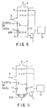
- FIG. 8 A conventional wet FGD unit according to the lime gypsum method is shown in FIG. 8.
- An exhaust gas 4 including a sulfur oxide is introduced into an absorption tower 1, is then brought into contact with a slurry sprayed from a spray nozzle 5 so that the exhaust gas is desulfurized, and this desulfurized exhaust gas is exhausted from the top portion of the absorption tower 1.
- the sulfur oxide reacts with the slaked lime or calcium carbonate included in the spayed slurry, or is absorbed in a spray liquid and then reacts with the slaked lime or calcium carbonate to be added in a liquid storage bath 2, and becomes calcium sulfite.
- the calcium sulfite is oxidized by finely blown air sent from a diffuser 6 within the liquid storage bath 2 to become gypsum.
- the liquid in the liquid storage bath is stirred by a stirrer 13, and there is also a case where minute air bubbles are generated by using the shearing force of this stirrer.
- the air blowing position is not particularly specified when the liquid in the liquid storage bath is stirred sufficiently (as described, for example, in the Jpn. Pat. Appln. KOKAI Publication No. 6-285327), and the air blowing position is at a middle stage section or in an upper area with low pH when the stirring is controlled to the extent of restricting the sedimentation of a solid material (as described, for example, in the Jpn. Pat. Appln. KOKOKU Publication No. 62-55890 and the Jpn. Pat. Appln. KOKOKU Publication No. 1-59004).
- the slurry including the gypsum after finishing the oxidation reaction is sent to the spray nozzle 5 and a gypsum recovering unit 8 by pressure by a slurry pump 7.
- the concentration of the sulfur oxide included in the gas to be processed is increased while maintaining the purity of the gypsum to be generated at 99% or above based on this prior-art technique, there is a limitation to the concentration of the sulfur oxide that can be processed if the same unit is used. Although the concentration of the sulfur oxide that can be processed increases along with an increase in the excess supply quantity of the blowing air, this is not effective and there is also an upper limit to the achievable concentration.
- the above-described object is achieved by carrying out an oxidation reaction in the whole areas of the liquid storage bath while restricting the stirring in the upward and downward directions of the liquid storage bath to the minimum.
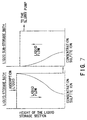
- the liquid in the liquid storage bath has three layers, from the top surface of the liquid, of a non-reaction section in which a reaction is not carried out because oxygen is not supplied to this section though sulfite ion exists in this section, a reaction zone in which an oxidation reaction is progressed further with a lowered concentration of the sulfite ion toward the larger depth of the liquid, and a complete oxidation section in which dissolved oxygen is saturated and there exists no sulfite ion.
- the air blowing quantity in this case is set as a minimum air blowing quantity. It is possible to increase the load of the sulfur oxide until the widths of the non-reaction section and the complete oxidation section are reduced and the reaction zone is expanded to the whole areas of the liquid storage bath. In this case, the concentration of the sulfite ion that takes a maximum value at the liquid surface is lowered as the liquid depth larger and the sulfite ion disappears at the bottom section of the liquid storage bath.
- the minimum quantity of blowing air when the concentration of the sulfur oxide in the exhaust gas 4 is increased and the quantity of the sulfur oxide supplied to the liquid storage bath is increased is as shown in FIG. 6.
- the width of the reaction zone increases.
- the reaction zone moves up and down between the liquid top surface and the marginal liquid depth at which the sulfite ion is immediately before leaking out to the slurry pump 7.
- the minimum quantity of blowing air increases substantially proportional to the concentration of the sulfur oxide until the upper surface of the reaction zone reaches the liquid top surface and the lower surface of the reaction zone reaches the depth of the liquid immediately before the point at which the sulfite ion is leaked out.
- an increase in the air blowing quantity increases the stirring in the upward and downward directions of the slurry in the liquid storage bath. This has the operation of expanding the width of the reaction zone as described later and this further increases the additional quantity of blowing air.
- the increase in the air blowing quantity means the increase in the cost of the air blowing unit. In the actual unit, it is desirable to operate the unit under the condition of immediately before a sudden increase in the air blowing quantity.
- the stirrer as described with reference to FIG. 6, the quantity of the sulfur oxide that can be loaded when the minimum quantity of blowing air increases suddenly, that is the load limit of the unit, is lowered.
- the stirring is for expanding the width of the reaction zone.
- a reduction in the load margin due to the increase in the stirring efficiency is also generated when a large-scale unit is prepared, and this becomes an interference.
- the liquid storage bath in which the oxidation reaction is carried out over the whole areas is divided into two sections, and the mixing of the slurry is restricted effectively so that the total volume of slurry is decreased.
- the present invention has the following structures.
- a liquid sub-storage bath 3 is provided at the side of an absorption tower 1, and the bottom section of a liquid storage bath 2 of the absorption tower is connected to the liquid sub-storage bath 3 through a liquid flowing section 11.
- the connection point of the liquid sub-storage bath 3 is not particularly limited to the bottom section but this may be an upper section.
- the upper section of the liquid sub-storage bath 3 is connected directly to the bottom section of the liquid storage bath 2 or a slurry extracted from the bottom section of the liquid storage bath 2 is sent to the upper section of the liquid sub-storage bath 3.
- An example of having both bottom sections connected together will be explained below.
- the shapes of the cross sections of the liquid storage bath 2 and the liquid sub-storage bath 3 are not particularly limited to a circular shape.
- Diffusers 6 for blowing air are installed at the bottom section of the absorption tower liquid storage bath 2, and an oxidation is carried out by restricting the stirring in the upward and downward directions.
- the slurry which has been oxidated insufficiently is sent to the liquid sub-storage bath 3 equipped with the diffusers 6 and this slurry is oxidated again while restricting the stirring in the upward and downward directions.
- the pH of the slurry is lowered by the generation of a sulfurous acid or a sulfuric acid
- the pH is neutralized by inputting a slurry of slaked lime or calcium carbonate in the liquid storage bath 2, the liquid sub-storage bath 3 and/or in the piping between the exit of the liquid sub-storage bath 3 and a slurry pump 7.
- the pH is controlled at a value of pH 5.5 or below at which the oxidation reaction is progressed quickly over the whole areas of the liquid storage bath 2 and the liquid sub-storage bath 3.
- This slurry may be input to any position, either to one position or to a plurality of positions, of the liquid storage bath 2, the liquid sub-storage bath 3 and the piping between the exit of the liquid sub-storage bath 3 and the slurry pump 7. Since scales can be easily generated in the liquid flowing section 11, the liquid flowing section 11 needs to be as thick and short as possible.
- Ejectors which have high dissolving efficiency of oxygen are desirable for the diffusers 6.
- the ejectors use a part of the slurry emitted from the slurry pump 7 as a driving liquid and suck air by a negative pressure generated by this.
- the cross section of the liquid storage bath is formed in a circular shape, and the ejectors are disposed by a plurality of number in the whole areas of the bottom section of the liquid storage bath as shown in FIG. 4. It is further desirable that a circular flow is formed by avoiding an occurrence of a falling flow of the liquid from the upper section and the air bubbles are dispersed thoroughly.
- a thorough dispersion of the air bubbles in the horizontal direction makes it possible to reduce the width of the reaction zone and to increase the quantity of the sulfur oxide that can be loaded to the per unit volume of the slurry. Further, according to this system, there does not occur a sedimentation of gypsum particles at the bottom section of the liquid storage bath, and it is not particularly necessary to install a stirrer.
- the quantity of blowing air is as small as possible in order to be able to restrict the quantity of oxygen to be discharged without being consumed in the slurry to the minimum and to restrict the stirring of the slurry in the upward and downward directions.
- a desirable quantity of blowing air is the one which can restrict the concentration of the dissolved oxygen at the liquid surface of the liquid storage bath 2 and the liquid sub-storage bath 3 respectively to 1 ppm or below.
- the gas discharged from the liquid surface of the liquid sub-storage bath 3 may be discharged straight into the atmosphere. However, it is desirable that this gas is returned to the absorption tower 1 through a gas flowing section 12 because a slight volume of sulfur oxide might be included in this gas.
- the slurry after having been oxidated completely at the upper section of the liquid sub-storage bath 3 is extracted by the slurry pump 7, and is then sent by pressure to a gypsum recovering unit 8 and a spray nozzle 5.
- a gypsum recovering unit 8 and a spray nozzle 5 When the quantity of blowing air is controlled so that the oxidation-reduction potential of the slurry sent to the slurry pump 7 from the liquid sub-storage bath 3 becomes 250 mV or above, a high-purity gypsum including no non-oxidated material is obtained from the gypsum recovering unit.
- the reduction in the desulfurization rate is because the quantity of the absorption liquid to be supplied from the spray nozzle is set at the same as that of the comparative example although a higher exhaust-gas flow rate was used than the exhaust-gas flow rate of the comparative example.
- the value of desulfurization rate can be increased by increasing the quantity of the absorption liquid.
- the quantity of sulfur oxide that can be processed per one hour increased to 4.1 Nm 3 for 1 m 3 volume of slurry in the liquid storage bath. Further, the proportion of oxygen in the air blown used for the oxidation reaction increased to 78%.
- the liquid bath in an absorption tower 1a is partitioned by a bulkhead 9 provided with a liquid flowing section 11 at its bottom section, and a roof 10 is installed in only a liquid storage bath 3a and a slurry having absorbed a sulfur oxide flows to only a liquid storage bath 2a.
- the cross sectional shape of the liquid storage bath of the absorption tower 1a is not particularly limited to a circular shape.
- Diffusers 6 are installed at the bottom section of the absorption tower 1a, a slurry insufficiently oxidated in the liquid storage bath 2a while restricting the stirring in the upward and downward directions is sent to the liquid sub-storage bath 3a having the roof, and this slurry is oxidated again in this bath by restricting the stirring in the upward and downward directions. It is suitable to set the volume ratio of the liquid storage bath 2a to the liquid sub-storage bath 3a between 70 : 30 and 30 : 70.
- the pH of the slurry is lowered by the generation of a sulfurous acid or a sulfuric acid
- the pH is neutralized by inputting a slurry of slaked lime or calcium carbonate in the liquid storage bath 2a, the liquid sub-storage bath 3a and/or in the piping between the exit of the liquid sub-storage bath 3a and a slurry pump 7.
- the pH is controlled at a value of pH 5.5 or below at which the oxidation reaction is progressed quickly over the whole areas of the liquid storage bath 2a and the liquid sub-storage bath 3a.
- This slurry may be input to any position, either to one position or to a plurality of positions, of the liquid storage bath 2a, the liquid sub-storage bath 3a and the piping between the exit of the liquid sub-storage bath 3a and the slurry pump 7. Since scales can be easily generated in the liquid flowing section 11, the liquid flowing section 11 needs to be as large as possible to the extent that the restriction of the mixing in the two liquid storage baths is not interrupted.
- Ejectors which have high dissolving efficiency of oxygen are desirable for the diffusers 6.
- the type is not limited to this.
- the ejectors use a part of the slurry emitted from the slurry pump 7 as a driving liquid and suck air by a negative pressure generated by this.
- the cross section of the liquid storage bath is formed in a circular shape, and the ejectors are disposed at the bottom section of the absorption tower 1a by a plurality of number in the whole areas of the bottom section of the liquid storage bath as shown in FIG. 4.
- a circular flow is formed by avoiding an occurrence of a falling flow of the liquid from the upper section and the air bubbles are dispersed thoroughly in the horizontal direction. Further, according to this system, there does not occur a sedimentation of gypsum particles at the bottom section of the liquid storage bath, and it is not particularly necessary to install a stirrer.
- the quantity of blowing air is as small as possible in order to restrict the stirring of the slurry in the upward and downward directions.
- a desirable quantity of blowing air is the one which can restrict the concentration of the dissolved oxygen at the liquid surface of the liquid storage bath 2a and the liquid sub-storage bath 3a respectively to 1 ppm or below.
- the gas discharged from the liquid surface of the liquid sub-storage bath 3a may be discharged straight into the atmosphere. However, it is desirable that this gas is returned to the absorption tower 1a through a gas flowing section 12 because a slight volume of sulfur oxide might be included in this gas.
- the bulkhead 9 should not be installed in the range at least from the bottom section to the 1m height, and this section having no bulkhead may be used as the liquid flowing section 11.
- a liquid storage bath of an absorption tower 1b is partitioned by a cylindrical bulkhead 9a provided with a liquid flowing section 11 at its bottom section so as to have a double structure of an inside liquid storage bath 2b and an outside liquid sub-storage bath 3b, and a slurry including a sulfur oxide flows into only the inside liquid storage bath 2a.
- the cross sectional shapes of the absorption tower 1b and the liquid storage baths with the bulkhead 9a are not particularly limited to circular shapes.
- the bulkhead 9a may be a tube shape, not limited to circular cross sectional shape.
- Diffusers 6 are installed at the bottom section of the absorption tower 1b, a slurry insufficiently oxidated in the inside liquid storage bath 2b while restricting the stirring in the upward and downward directions is sent to the outside liquid sub-storage bath 3b, and this slurry is oxidated again in this bath by restricting the stirring in the upward and downward directions. It is suitable to set the volume ratio of the liquid storage bath 2b to the liquid sub-storage bath 3b between 50 : 50 and 20 : 80.
- the outside liquid sub-storage bath 3b since the outside liquid sub-storage bath 3b has a structure particularly suitable for restricting the stirring in the upward and downward directions, the outside liquid sub-storage bath 3b can take a large volume.
- the pH of the slurry is lowered by the generation of a sulfurous acid or a sulfuric acid
- the pH is neutralized by inputting a slurry of slaked lime or calcium carbonate in the liquid storage bath 2b, the liquid sub-storage bath 3b and/or in the piping between the exit of the liquid sub-storage bath 3b and a slurry pump 7.
- the pH is controlled at a value of pH 5.5 or below at which the oxidation reaction is progressed quickly over the whole areas of the liquid storage bath 2b and the liquid sub-storage bath 3b. Since scales can be easily generated in the liquid flowing section 11, the liquid flowing section 11 needs to be as large as possible to the extent that the restriction of the mixing in the two liquid storage baths is not interrupted.
- Ejectors which have high dissolving efficiency of oxygen are desirable for the diffusers 6.
- the type is not limited to this.
- the ejectors use a part of the slurry emitted from the slurry pump 7 as a driving liquid and suck air by a negative pressure generated by this.
- the cross sectional shapes of the absorption tower 1b and the cylindrical bulkhead 9a are formed in circular shapes, and the ejectors are disposed at the bottom section of the absorption tower 1b by a plurality of number in the whole areas of the bottom section of the liquid storage bath as shown in FIG. 4.
- a circular flow is formed by avoiding an occurrence of a falling flow of the liquid from the upper section and the air bubbles are dispersed thoroughly in the horizontal direction. Further, according to this system, there does not occur a sedimentation of gypsum particles at the bottom section of the liquid storage bath, and it is not particularly necessary to install a stirrer.
- the quantity of blowing air is as small as possible in order to restrict the stirring of the slurry in the upward and downward directions.
- a desirable quantity of blowing air is the one which can restrict the concentration of the dissolved oxygen at the liquid surface of the liquid storage bath 2b and the liquid sub-storage bath 3b respectively to 1 ppm or below.
- the gas discharged from the liquid surface of the liquid sub-storage bath 3b may be discharged straight into the atmosphere. However, it is desirable that this gas is returned to the absorption tower 1b through a gas flowing section 12 because a slight volume of sulfur oxide might be included in this gas.
- the present invention it becomes possible to reduce the volume of the slurry in the liquid storage bath at the lower portion of the absorption tower while restricting the quantity of the blowing air to the minimum and securing the purity of the gypsum to be generated, for a combustion exhaust gas including a high-concentration sulfur oxide.
Landscapes
- Engineering & Computer Science (AREA)
- Chemical & Material Sciences (AREA)
- Environmental & Geological Engineering (AREA)
- Health & Medical Sciences (AREA)
- Biomedical Technology (AREA)
- Analytical Chemistry (AREA)
- General Chemical & Material Sciences (AREA)
- Oil, Petroleum & Natural Gas (AREA)
- Chemical Kinetics & Catalysis (AREA)
- Treating Waste Gases (AREA)
Abstract
Description
Claims (6)
- A wet FGD (flue gas desulfurization) method for introducing a combustion exhaust gas including a sulfur oxide of 1 volume percent or above into an absorption tower, desulfurizing said combustion exhaust gas by bringing it into contact with a slurry including slaked lime or calcium carbonate, blowing air into said slurry stored at a lower portion of said absorption tower to make said slurry as a gypsum slurry, and recovering a part of said gypsum slurry with the rest being re-circulated as an absorption liquid for said sulfur oxide, whereina liquid sub-storage bath is provided at the side of said absorption tower, with said liquid sub-storage bath connected with a bottom section of a liquid storage bath of said absorption tower, and air is blown from diffusers disposed at both bottom sections of said liquid storage bath of said absorption tower and said liquid sub-storage bath so that said slurry that has been oxidated insufficiently in said liquid storage bath of said absorption tower is oxidated completely in said liquid sub-storage bath and then said completely oxidated slurry is extracted.
- A wet FGD method for introducing a combustion exhaust gas including a sulfur oxide of 1 volume percent or above into an absorption tower, desulfurizing said combustion exhaust gas by bringing it into contact with a slurry including slaked lime or calcium carbonate, blowing air into said slurry stored at a lower portion of said absorption tower to make said slurry as a gypsum slurry, and recovering a part of said gypsum slurry with the rest being re-circulated as an absorption liquid for said sulfur oxide, whereina liquid storage bath of said absorption tower is partitioned by a bulkhead having a liquid flowing section at its bottom section, with a roof provided in only one of said partitioned liquid storage baths and said slurry including said sulfur oxide flowing into only the other liquid storage bath, and air is blown from diffusers disposed at both bottom sections of said liquid storage baths so that said slurry that has been oxidated insufficiently in said liquid storage bath without a roof is oxidated completely in said liquid sub-storage bath with said roof and then said completely oxidated slurry is extracted.
- A wet FGD method for introducing a combustion exhaust gas including a sulfur oxide of 1 volume percent or above into an absorption tower, desulfurizing said combustion exhaust gas by bringing it into contact with a slurry including slaked lime or calcium carbonate, blowing air into said slurry stored at a lower portion of said absorption tower to make said slurry as a gypsum slurry, and recovering a part of said gypsum slurry with the rest being re-circulated as an absorption liquid for said sulfur oxide, whereina liquid storage bath of said absorption tower is partitioned by a cylindrical bulkhead having a liquid flowing section at its bottom section so as to have a double structure of inside and outside liquid storage baths, with said slurry including said sulfur oxide flowing into only said inside liquid storage bath, and air is blown from diffusers disposed at both bottom sections of said liquid storage baths so that said slurry that has been oxidated insufficiently in said inside liquid storage bath is oxidated completely in said outside liquid sub-storage bath and then said completely oxidated slurry is extracted.
- A wet FGD method according to claim 1, wherein the volume ratio of said liquid storage bath to said liquid sub-storage bath is set at values between 70 : 30 and 30 : 70.
- A wet FGD method according to claim 2, wherein the volume ratio of said liquid storage bath without a roof to said liquid sub-storage bath with said roof is set at values between 70 : 30 and 30 : 70.
- A wet FGD method according to claim 3, wherein the volume ratio of said inside liquid storage bath to said outside liquid sub-storage bath is set at values between 50 : 50 and 20 : 80.
Applications Claiming Priority (1)
| Application Number | Priority Date | Filing Date | Title |
|---|---|---|---|
| PCT/JP1997/003583 WO1999017863A1 (en) | 1996-04-08 | 1997-10-07 | Wet type exhaust gas desulfurization method |
Publications (3)
| Publication Number | Publication Date |
|---|---|
| EP0945164A1 true EP0945164A1 (en) | 1999-09-29 |
| EP0945164A4 EP0945164A4 (en) | 1999-12-08 |
| EP0945164B1 EP0945164B1 (en) | 2002-11-06 |
Family
ID=14181265
Family Applications (1)
| Application Number | Title | Priority Date | Filing Date |
|---|---|---|---|
| EP97942268A Expired - Lifetime EP0945164B1 (en) | 1997-10-07 | 1997-10-07 | Wet type exhaust gas desulfurization method |
Country Status (4)
| Country | Link |
|---|---|
| EP (1) | EP0945164B1 (en) |
| KR (1) | KR100278324B1 (en) |
| DE (1) | DE69716942D1 (en) |
| WO (1) | WO1999017863A1 (en) |
Cited By (6)
| Publication number | Priority date | Publication date | Assignee | Title |
|---|---|---|---|---|
| EP1707875A1 (en) * | 2005-03-18 | 2006-10-04 | Lurgi Lentjes AG | Smoke purifier apparatus with improved oxidation device in the washing fluid sump |
| US7438879B2 (en) | 2005-03-18 | 2008-10-21 | Lentjes Gmbh | Purification device for flue gas with divided scrubbing liquid sump |
| US7514054B2 (en) | 2005-03-18 | 2009-04-07 | Lentjes Gmbh | Flue gas purification device having an essentially horizontal through flow |
| CN104941420A (en) * | 2014-06-25 | 2015-09-30 | 青岛绿洲源环境工程有限公司 | Flue gas desulfurization comprehensive treatment system and method |
| US9157032B2 (en) | 2013-02-19 | 2015-10-13 | Uop Llc | Process for oxidizing one or more thiol compounds |
| EP3124096A1 (en) * | 2015-07-30 | 2017-02-01 | Steinmüller Babcock Environment GmbH | Limestone/hydrated lime - flue gas purification system with clean gas bypass channel and sump extension system |
Families Citing this family (2)
| Publication number | Priority date | Publication date | Assignee | Title |
|---|---|---|---|---|
| US9028762B2 (en) * | 2012-07-30 | 2015-05-12 | Mitsubishi Hitachi Power Systems, Ltd. | Wet type exhaust gas desulfurization apparatus |
| CN104353338A (en) * | 2014-10-28 | 2015-02-18 | 南京大学(苏州)高新技术研究院 | Cross flow-type desulfurization device |
Family Cites Families (4)
| Publication number | Priority date | Publication date | Assignee | Title |
|---|---|---|---|---|
| JP2738954B2 (en) * | 1989-05-08 | 1998-04-08 | 三菱重工業株式会社 | Method for treating exhaust gas containing SO2 and HF |
| JPH05329327A (en) * | 1992-06-01 | 1993-12-14 | Ishikawajima Harima Heavy Ind Co Ltd | Absorption tower |
| AT402264B (en) * | 1995-09-07 | 1997-03-25 | Austrian Energy & Environment | METHOD AND DEVICE FOR WET SEPARATION OF ACID GASES |
| JPH09271633A (en) * | 1996-04-08 | 1997-10-21 | Nkk Corp | Wet flue gas desulfurization method |
-
1997
- 1997-10-07 EP EP97942268A patent/EP0945164B1/en not_active Expired - Lifetime
- 1997-10-07 WO PCT/JP1997/003583 patent/WO1999017863A1/en not_active Ceased
- 1997-10-07 DE DE69716942T patent/DE69716942D1/en not_active Expired - Lifetime
-
1998
- 1998-05-28 KR KR19980703992A patent/KR100278324B1/ko not_active Expired - Fee Related
Cited By (8)
| Publication number | Priority date | Publication date | Assignee | Title |
|---|---|---|---|---|
| EP1707875A1 (en) * | 2005-03-18 | 2006-10-04 | Lurgi Lentjes AG | Smoke purifier apparatus with improved oxidation device in the washing fluid sump |
| US7438879B2 (en) | 2005-03-18 | 2008-10-21 | Lentjes Gmbh | Purification device for flue gas with divided scrubbing liquid sump |
| US7514054B2 (en) | 2005-03-18 | 2009-04-07 | Lentjes Gmbh | Flue gas purification device having an essentially horizontal through flow |
| US7635455B2 (en) | 2005-03-18 | 2009-12-22 | Lentjes Gmbh | Flue gas purification device having an improved oxidation device in the scrubbing liquid sump |
| US9157032B2 (en) | 2013-02-19 | 2015-10-13 | Uop Llc | Process for oxidizing one or more thiol compounds |
| CN104941420A (en) * | 2014-06-25 | 2015-09-30 | 青岛绿洲源环境工程有限公司 | Flue gas desulfurization comprehensive treatment system and method |
| EP3124096A1 (en) * | 2015-07-30 | 2017-02-01 | Steinmüller Babcock Environment GmbH | Limestone/hydrated lime - flue gas purification system with clean gas bypass channel and sump extension system |
| WO2017016821A1 (en) * | 2015-07-30 | 2017-02-02 | Steinmüller Babcock Environment Gmbh | Limestone/lime hydrate flue-gas cleaning installation having a clean-gas bypass channel and a sump expansion system |
Also Published As
| Publication number | Publication date |
|---|---|
| EP0945164A4 (en) | 1999-12-08 |
| KR100278324B1 (en) | 2001-01-15 |
| DE69716942D1 (en) | 2002-12-12 |
| WO1999017863A1 (en) | 1999-04-15 |
| EP0945164B1 (en) | 2002-11-06 |
Similar Documents
| Publication | Publication Date | Title |
|---|---|---|
| US3892837A (en) | Process for removing sulfur oxides from gases | |
| JP2012115764A (en) | Wastewater channel of seawater desulfurization apparatus and seawater flue gas desulfurization system | |
| EP0945164B1 (en) | Wet type exhaust gas desulfurization method | |
| US6759019B1 (en) | Process for desulfurization of exhaust gas with seawater | |
| JP3564289B2 (en) | Method and apparatus for treating desulfurization absorbent | |
| JPH0780243A (en) | Desulfurization method and equipment with high-concentration desulfurization agent slurry | |
| WO1996014137A1 (en) | Forced oxidation system for a flue gas scrubbing apparatus | |
| JP2013158720A (en) | Desulfurization seawater treatment system | |
| CN103721551B (en) | Boiler flue gas desulfurization, denitration, demercuration integrated purifying equipment | |
| KR101701015B1 (en) | Flue gas desulfurization system | |
| JP3337382B2 (en) | Exhaust gas treatment method | |
| JPH1094714A (en) | Exhaust gas treatment method | |
| JP2014233702A (en) | Seawater desulfurization device and seawater desulfurization system | |
| JPH09271633A (en) | Wet flue gas desulfurization method | |
| JP6742830B2 (en) | Seawater plant with tilted aeration and mixed automatic recovery | |
| JPH08126812A (en) | Wet flue gas desulfurization equipment | |
| JPH11290646A (en) | Wet flue gas desulfurization method and equipment | |
| JPH10137539A (en) | Flue gas desulfurization method and apparatus using coarse solid desulfurizing agent | |
| TW201840353A (en) | Desulfurizing method and desulfurizing device | |
| JP3504427B2 (en) | Exhaust gas desulfurization method | |
| JPH08243348A (en) | Operation method of wet desulfurization equipment | |
| JPH08224437A (en) | Wet flue gas desulfurization apparatus and method | |
| JP3805783B2 (en) | Two-chamber wet flue gas desulfurization apparatus and method | |
| JPS62204828A (en) | Method for controlling oxidizing air of wet exhaust gas desulfurizing device | |
| JPH06285327A (en) | Flue gas desulfurization method and device |
Legal Events
| Date | Code | Title | Description |
|---|---|---|---|
| PUAI | Public reference made under article 153(3) epc to a published international application that has entered the european phase |
Free format text: ORIGINAL CODE: 0009012 |
|
| 17P | Request for examination filed |
Effective date: 19980312 |
|
| AK | Designated contracting states |
Kind code of ref document: A1 Designated state(s): BE DE DK FR GB |
|
| A4 | Supplementary search report drawn up and despatched |
Effective date: 19991021 |
|
| AK | Designated contracting states |
Kind code of ref document: A4 Designated state(s): BE DE DK FR GB |
|
| 17Q | First examination report despatched |
Effective date: 20000602 |
|
| GRAG | Despatch of communication of intention to grant |
Free format text: ORIGINAL CODE: EPIDOS AGRA |
|
| GRAG | Despatch of communication of intention to grant |
Free format text: ORIGINAL CODE: EPIDOS AGRA |
|
| GRAH | Despatch of communication of intention to grant a patent |
Free format text: ORIGINAL CODE: EPIDOS IGRA |
|
| GRAH | Despatch of communication of intention to grant a patent |
Free format text: ORIGINAL CODE: EPIDOS IGRA |
|
| GRAH | Despatch of communication of intention to grant a patent |
Free format text: ORIGINAL CODE: EPIDOS IGRA |
|
| GRAA | (expected) grant |
Free format text: ORIGINAL CODE: 0009210 |
|
| AK | Designated contracting states |
Kind code of ref document: B1 Designated state(s): BE DE DK FR GB |
|
| PG25 | Lapsed in a contracting state [announced via postgrant information from national office to epo] |
Ref country code: FR Free format text: LAPSE BECAUSE OF FAILURE TO SUBMIT A TRANSLATION OF THE DESCRIPTION OR TO PAY THE FEE WITHIN THE PRESCRIBED TIME-LIMIT Effective date: 20021106 Ref country code: BE Free format text: LAPSE BECAUSE OF FAILURE TO SUBMIT A TRANSLATION OF THE DESCRIPTION OR TO PAY THE FEE WITHIN THE PRESCRIBED TIME-LIMIT Effective date: 20021106 |
|
| REG | Reference to a national code |
Ref country code: GB Ref legal event code: FG4D |
|
| REF | Corresponds to: |
Ref document number: 69716942 Country of ref document: DE Date of ref document: 20021212 |
|
| PG25 | Lapsed in a contracting state [announced via postgrant information from national office to epo] |
Ref country code: DK Free format text: LAPSE BECAUSE OF FAILURE TO SUBMIT A TRANSLATION OF THE DESCRIPTION OR TO PAY THE FEE WITHIN THE PRESCRIBED TIME-LIMIT Effective date: 20030206 |
|
| PG25 | Lapsed in a contracting state [announced via postgrant information from national office to epo] |
Ref country code: DE Free format text: LAPSE BECAUSE OF FAILURE TO SUBMIT A TRANSLATION OF THE DESCRIPTION OR TO PAY THE FEE WITHIN THE PRESCRIBED TIME-LIMIT Effective date: 20030207 |
|
| EN | Fr: translation not filed | ||
| PLBE | No opposition filed within time limit |
Free format text: ORIGINAL CODE: 0009261 |
|
| STAA | Information on the status of an ep patent application or granted ep patent |
Free format text: STATUS: NO OPPOSITION FILED WITHIN TIME LIMIT |
|
| PG25 | Lapsed in a contracting state [announced via postgrant information from national office to epo] |
Ref country code: GB Free format text: LAPSE BECAUSE OF NON-PAYMENT OF DUE FEES Effective date: 20031007 |
|
| 26N | No opposition filed |
Effective date: 20030807 |
|
| GBPC | Gb: european patent ceased through non-payment of renewal fee |
Effective date: 20031007 |