FIELD OF THE INVENTION
This invention relates to the structure of a motor/generator.
BACKGROUND OF THE INVENTION
Tokkai Hei 8-340663 published by the Japanese Patent Office in 1996
discloses a motor/generator comprising two rotors and one stator coaxially
arranged in three layers wherein one of the rotors is driven as a motor and the
other is driven as a generator.
In this motor/generator, two sets of coils are installed in the stator for
providing a magnetic field for respective rotors, and two sets of inverters, i.e.,
current controllers, are provided for controlling respective sets of coils.
SUMMARY OF THE INVENTION
However, in the case of this motor/generator, since two series of coils
and inverters are required, there is a problem in that current losses such as
copper loss and switching loss, are large.
It is therefore an object of this invention to reduce current losses of such
a three-layered motor/generator as described in the prior art.
It is another object of this invention to simplify the construction and
reduce the number of parts of such a motor/generator.
In order to achieve the above objects, this invention provides a
motor/generator, comprising a first rotor comprising plural magnetic poles
and supported free to rotate, a second rotor comprising plural magnetic poles
and supported free to rotate coaxially with the first rotor, a stator fixed
co-axially with the first rotor, and a coil unit comprising plural coils disposed
at equal angular intervals on the stator.
The coil unit is arranged so as to form plural rotating magnetic fields of
equal number to the number of magnetic poles of the first rotor according to a
first alternating current and to form plural rotating magnetic fields of equal
number to the number of magnetic poles of the second rotor according to a
second alternating current.
The coil unit comprises first salient poles facing the first rotor and
second salient poles facing the second rotor, wherein the ratio of the first
salient poles and second salient poles is set equal to the ratio of a magnetic
pole number of the first rotor and a magnetic pole number of the second rotor.
The motor/generator further comprises an electrical circuit for supplying
a composite electrical current comprising the first alternating current and the
second alternating current to the coil unit.
The details as well as other features and advantages of this invention are
set forth in the remainder of the specification and are shown in the accompanying
drawings.
BRIEF DESCRIPTION OF THE DRAWINGS
Fig. 1 is a schematic cross-sectional view of a motor/generator according
to this invention.
Fig. 2 is a schematic cross-sectional view of a motor/generator comprising
coils arranged on the inner circumference and outer circumference of a stator,
assumed for the purpose of describing a composite current according to this
invention.
Fig. 3 is a schematic diagram of a control circuit according to this
invention.
Fig. 4 is a circuit diagram of an inverter according to this invention.
Fig. 5 is a schematic cross-sectional view of a motor /generator according
to a second embodiment of this invention.
Fig. 6 is is similar to Fig. 5, but showing a third embodiment of this
invention.
Fig. 7 is a schematic cross-sectional view of a motor/generator having a
magnetic pole number ratio of 1:1 set as a model for performing a theoretical
analysis of magnetic flux and rotation torque.
Figs. 8A-8C are diagrams showing a variation of magnetic flux density in
the motor/generator of Fig. 7.
Fig. 9 is a schematic cross-sectional view of a motor/generator having a
magnetic pole number ratio of 2:1 and coils arranged on the inner circumference
and outer circumference of a stator, assumed for the purpose of describing a
composite current according to this invention.
Figs. 10A-10D are diagrams showing a variation of magnetic flux density
in the motor/generator of Fig. 9.
Fig. 11 is similar to Fig. 9, but showing a case where the coils on the
inner and outer circumferences are integrated.
Figs. 12A-12B are diagrams showing a distribution of alternating current
for driving the motor/generator of Fig. 11.
Fig. 13 is similar to Fig. 9, but showing a case where the magnetic pole
number ratio is 3:1.
Figs. 14A - 14D are diagrams showing a variation of magnetic flux density
in the motor/generator of Fig. 13.
Figs. 15A-15C are diagrams describing magnetic force interference in the
motor/generator of Fig. 13.
Fig. 16 is similar to Fig. 13, but showing a case where the coils on the
inner and outer circumferences are integrated.
Figs. 17A, 17B are diagrams showing a distribution of alternating current
for driving the motor/generator of Fig. 16.
Fig. 18 is a schematic diagram of a motor/generator according to a fourth
embodiment of this invention.
Fig. 19 is similar to Fig. 18, but showing a fifth embodiment of this
invention.
Fig. 20 is similar to Fig. 18, but showing a sixth embodiment of this
invention.
Fig. 21 is similar to Fig. 18, but showing a seventh embodiment of this
invention.
Fig. 22 is similar to Fig. 18, but showing an eighth embodiment of this
invention.
DESCRIPTION OF THE PREFERRED EMBODIMENTS
Referring to Fig. 1 of the drawings, a motor /generator 1 has a three-layer
construction comprising a cylindrical stator 2 and rotors 3, 4 arranged with a
predetermined clearance outside and inside the stator 2.
The stator 2, outer rotor 3 and inner rotor 4 are arranged coaxially. The
stator 2 is fixed to a casing 41 of the motor/generator 1 as shown in Fig. 3.
The outer rotor 3 is fixed to a frame 5, and the frame 5 rotates relative to the
casing 41 via an axis 18. The inner rotor 4 rotates relative to the casing 41
via an axis 19.
The inner rotor 4 comprises permanent magnets having N poles and S
poles respectively arranged on each of two semicircles, as shown in Fig. 1.
The outer rotor 3 comprises permanent magnets having a pole number
two times that of the rotor 4 with two S poles and N poles alternately
arranged at 90 degree intervals.
According to this arrangement, the permanent magnets of the outer rotor
3 do not exert a rotation force on the permanent magnets of the inner rotor 4,
nor vice-versa, due to the following reason.
In the state shown in Fig. 1, assume that the S poles of the inner rotor 4
exert a rotation force in a clockwise direction on the N poles and S poles in
the upper part of the drawing of the outer rotor 3. At that time, the permanent
magnet N poles and S poles in the lower part of the outer rotor 3 tend to
rotate in an anticlockwise direction due to the magnetic force of the N poles of
the inner rotor. Therefore a rotation force acting on the N poles and S poles
in upper part of drawing is offset by a rotation force acting on the N poles and
S poles in the lower part of the drawing, so a rotation force does not act
between the outer rotor 3 and inner rotor 4. In other words, both the outer
rotor 3 and inner rotor 4 rotate only due to the magnetic force received from
the stator 2.
The stator 2 comprises twelve coils 6wound around six cores 7. The cores
7 are arranged at equal intervals in a circumferential direction across gaps 9.
To reduce the total number of the cores 7, each of the cores 7 is split into two
parts by slits 7A, and two of the coils 6 are wound on one of the cores 7.
These slits 7A have openings on the outer circumference of the stator 2.
As a result, two salient poles 7B, 7C are formed facing the outer rotor 3
on the outer circumference of each core 7, and one salient pole 7D is formed
facing the inner rotor 4 on the inner circumference of each core 7. In total,
twelve salient poles are formed on the outer circumference side, and six
salient poles are formed on the inner circumference side of the whole stator 2.
In other words, the total number of salient poles on the outer circumference
side is equal to the total number of coils, while the total number of salient
poles on the inner circumference side is a half of the total number of coils.
For the sake of convenience, the numbers shown in Fig. 1 are assigned to
these twelve coils 6. To distinguish them from part numbers, the symbol # is
attached before a number as in the coil #6 to indicate a coil number.
Currents l1 - l12 are passed into these twelve coils #1 - #12.
First, a three phase alternating current is passed into three sets of coils
to generate a rotational magnetic field relative to the inner rotor 4. Specifically,
a current is passed through the coils #1, #2, #7 and #8 so as to form a virtual
coil around a virtual axis which intersects perpendicularly with the rotating
axis of the rotor 3 (4). For this purpose, a current Id is passed through the
coils #1 and #2 in the reverse direction to the coils #7 and #8 which are
situated on the opposite side of the rotation axis of the rotor 3 (4) as center.
This is done by directing half a current Id through the coil #7 from the coil #1
and directing the other half of the current Id to the coil #8 from the coil #2.
As the coils #1 and #2 are adjacent to each other and the coils #7 and #8 are
also adjacent to each other, due to this current supply, the same situation
occurs as when the current Id flows through the virtual coil mentioned above,
and consequently, an N and a S pole are formed at the two ends of a virtual
axis.
Similarly, the coils #3, #4, #9, #10 form one set, and a current le flows
through these coils as if they formed one virtual coil around another virtual
axis rotated by 120 degrees from the aforesaid virtual axis.
Further, the remaining coils #5, #6, #11, #12 form one virtual coil around
another virtual axis rotated by 120 degrees, and a current If flows through
these coils.
Hence, three virtual coils are formed with winding axes which differ by
120 degrees, and an N pole and S pole region are formed every 180 degrees as
in the case of the inner rotor 3. A three-phase alternating current is supplied
to these sets of coils, and the resultant virtual coil progressively varies its
polarity according to the phase of the current. As a result, two pole rotating
magnetic fields are formed enclosing the inner rotor.
In this embodiment, the flow of the current is represented in the form
[#1,#2] = [#7,#8], [#3,#4] = [#9,#10], [#5,#6] = [#11,#12].
A coil with an underlined number means that a current is passed in the
reverse direction of a coil with a number which is not underlined.
Next, a three-phase current is passed into three sets of coils by the
following combination so as to generate a magnetic field relative to the outer
rotor 3.
[1] = [4] = [7] = [10], [2] = [5] = [8] = [11], [3] = [6] = [9] = [12]
In other words, a current la is passed to coil #4 from coil #1, and a
current la is made to flow to coil #10 from coil #7. Considering a line
connecting an intermediate point between coil #1 and #4 and an intermediate
point between coil #7 and #10 in Fig. 1 as a virtual axis, a virtual coil is
formed comprising coil #1 and #4 and a virtual coil is formed comprising coil
#7 and #10 around the axis due to the current la.
As the flow of current of these virtual coils is in opposite directions, an N
pole is formed for example at the two ends of the virtual axis and an S pole is
formed near the rotation axis of the rotor 3 (4) in the two sets of virtual coils.
Considering this on the periphery relative to the outer rotor 3, it is equivalent
to forming N poles and S poles alternately at 90 degrees intervals.
Similarly, for coils #2, #5, #8 and #10, a current Ib is passed. Similarly,
for coils #3, #6, #11 and #12, a current Ic is passed. Due to this, four-pole
rotating magnetic fields are formed relative to the outer rotor 3.
To satisfy the above conditions, the following currents l1 - l12 should be
passed through the twelve coils 6.
I1 = 1 2 ·Id+Ia
I2 = 1 2 ·Id+Ic
I3 = 1 2 ·If+lb
I4 = 1 2 ·If+la
I5 = 1 2 ·Ie+lc
I6 = 1 2 ·Ie+lb
I7 = 1 2 ·Id+la
I8 = 1 2 ·Id+lc
I9 = 1 2 ·If+lb
I10 = 1 2 ·If+la
I11 = 1 2 ·Ie+lc
I12 = 1 2 ·Ie+lb
A current in the reverse direction is shown by underlining added to the
current symbol.
Nest, referring to Fig. 2, the determination of the currents will be described.
Fig. 2 is provided for the purpose of comparison with the motor/generator in
Fig. 1. In the motor/generator in Fig. 2, specific coils d, f, e are provided for
rotating the inner rotor 4 and specific coils a, c, b are provided for rotating the
outer rotor 3.
In other words inner coil d, f, e form rotating magnetic fields relative to
the inner rotor 4 and outer coil a, c, b form rotating magnetic fields relative to
the outer rotor 3.
To combine these two groups of coils into the one group shown in Fig. 1,
of the inner coils in Fig. 2, half of the current passed into the coil d is taken
up by each of the coils a and c which are in the vicinity of the coil d, half of
the current passed into the coil f is taken up by each of the coils a and c
which are in the vicinity of the coil f, and half of the current passed into the
coil e is taken up by each of the coils c and b which are in the vicinity of the
coil e. The equations for the currents l1 - l12 mentioned above are mathematical
expressions of this concept. However, the currents may be set by other
methods described hereafter.
When this current setting is applied, two rotating magnetic fields can be
formed simultaneously, i.e., rotating magnetic fields relative to the inner rotor
4 and rotating magnetic fields relative to the outer rotor 3, despite the use of
one set of coils. Also, the rotating magnetic fields which the stator 2 forms
relative to the outer rotor 3 do not give a rotational torque to the permanent
magnets of the inner rotor 4, and the rotating magnetic fields which the stator
2 forms relative to the inner rotor 4 do not give a rotational torque to the
permanent magnets of the outer rotor 3. This point is verified by theoretical
analysis described later.
The frequency of the currents ld, lf, le is set based on a target rotation
speed of the inner rotor 4 and that of the currents la, lc, lb is set based on a
target rotation speed of the outer rotor 3.
Control of the motor/generator 1 is performed by a controller shown in
Fig. 3.
The controller comprises an inverter 12 to convert the direct current of a
battery power source 11 into alternating currents in order to supply the stator
2 with the currents l1 - l12 . This inverter 12 is a twelve-phase inverter comprising
twenty four transistors Tr1 - Tr24 and the same number of diodes as shown in
Fig. 4. This inverter 12 may be obtained by modifying an ordinary three-phase
inverter to have twelve phases.
An ON/OFF signal supplied to each gate of the inverter 12, i.e., base of
the transistors, is a pulse width modulation (PWM) signal.
Rotation angle sensors 14 and 13 to detect the phase of the rotors 3 and
4 are installed, and signals from these sensors 13 and 14 are input into a
control circuit 15.
The PWM signal is generated in the control circuit 15 based on positive or
negative torque command values input to the control circuit 15 specifying the
desired torque to be exerted on the outer rotor 3 and inner rotor 4.
In this way, in this motor/generator, two rotors 3 and 4 and one stator 2
are arranged coaxially in three layers, a series of coils 6 is provided in the
stator 2, and currents are passed to these coils 6 so as to generate rotating
magnetic fields inside and outside which are equal in number to the number
of magnetic poles of the rotors 3 and 4.
Therefore, when one of the rotors 3 and 4 is driven as a motor and the
other is driven as a generator, a current differential between the motor drive
force and the generator drive force may passed into the coils 6. It is not
necessary to provide specific coils for the rotors 3 and 4 separately as in the
aforesaid prior art. Hence, current losses are largely reduced.
Further, as the rotation of two rotors 3 and 4 can be controlled by a
single inverter 12, the cost of the inverter can be reduced, and as the power
switching transistor capacitance of the inverter is reduced, switching efficiency
improves.
In this way, of the salient poles formed on the outer circumference and
inner circumference of the stator 2, the total number of inner salient poles 7D
is arranged to be a half of the total number of coils 6, so the number of the
cores 7 can be reduced relative to the number of coils, and the number of
components of the stator 2 can be reduced.
Next, a second embodiment of the invention will be described referring to
Fig. 5.
According to this embodiment, the outer rotor 3 comprises six magnetic
poles and eighteen of the coils 6 are used for the stator 2. In the aforesaid first
embodiment, the magnetic pole number ratio of the outer rotor 3 and inner
rotor 4 was 2:1, but in this embodiment, the magnetic pole number ratio is
3:1. In other words, S and N poles alternate every 60 degree in the outer rotor
3.
In the stator 2, one core 21 is used for three coils. The stator 2 comprises
six of the cores 21 arranged at an equal interval with a predetermined gap 22
on the circumference. In each core 21, two slits 21A and 21B which open
toward the outer circumference are provided so as to split the core into three
parts.
Due to this, the core 21 comprises three salient poles 21C, 21D, 21E on
the outer circumference and one salient pole 21F on the inner circumference.
Overall, there are eighteen salient poles on the outer circumference and six
salient poles on the inner circumference. In other words, the total number of
salient poles on the outer circumference is equal to the number of coils 6, and
the number of salient poles on the inner circumference side is one third of the
total number of coils 6. In this embodiment also, the construction of the
stator 2 may be simplified by reducing the number of salient poles.
However when the magnetic pole number ratio is 3:1, unlike the case
where the magnetic pole number ratio is 2:1,the permanent magnets of the
inner rotor 4 are affected by the rotating magnetic fields formed by the stator 2
relative to the outer rotor 3, and a fluctuation occurs in the rotational torque
of the inner rotor 4. The permanent magnets of the outer rotor 3 do not
receive a rotational torque from the rotating magnetic fields formed by the
stator 2 relative to the inner rotor 4, so the rotational torque of the outer
rotor 3 is free from fluctuation.
From theoretical analysis described later, this torque fluctuation is a
function of the phase difference (omega1-omega2) of the outer rotor 3 and
inner rotor 4. Therefore, this torque fluctuation can be canceled by previously
applying an amplitude modulation to the alternating current which generates
the rotating magnetic fields relative to the outer rotor 3.
As a result, in this embodiment also, the outer rotor 3 and inner rotor 4
may basically be driven independently by a composite current as in the case
when the magnetic pole number ratio is 2:1.
Further, in this embodiment, an eighteen-phase alternating current is
passed through eighteen of the coils 6. However, as the phase of the alternating
current is actually reversed over half a semicircle, it is sufficient if the inverter
12 has a function to produce nine-phase alternating current. In other words,
the same current is passed in the reverse direction through coils #1 and # 10,
and the same current is passed in the reverse direction through coils #2 and
#11, coils #3 and #12, coils #4 and #13, coils #5 and #14, coils #6 and #15,
coils #7 and #16, coils #8 and #17, and coils #9 and #18.
Due to this, as the inverter 12 can be constructed from eighteen transistors
and eighteen diodes, the number of transistors and diodes can be reduced in
comparison to the aforesaid first embodiment.
Next, a third embodiment of the invention will be described referring to
Fig. 6.
This embodiment integrates six of the cores 21 of the aforesaid second
embodiment as a core 31 by providing a large resistor 32 of high magnetic
reluctance instead of the gap 22 of the aforesaid second embodiment.
The large resistor 32 comprises slits 32A and 32B which are respectively
provided on the outer circumference and inner circumference of the stator 2.
In this embodiment, eighteen salient poles are formed on the outer circumference
of the stator 2, and six salient poles are formed on the inner circumference as
in the aforesaid second embodiment.
Due to this, the number of parts and number of assembly steps of the
stator 2 are decreased more than in the aforesaid second embodiment.
The above-mentioned embodiment describe cases where the magnetic pole
number ratio was 2:1 or 3:1, but it can be shown from theoretical analysis
that the outer rotor 3 and inner rotor 4 can be driven using one type of the
coils 6 whatever the magnetic pole number ratio may be.
Next, the theoretical analysis of the driving forces acting on the rotors
will be performed with respect to the magnetic pole number ratios.
(1) N(2p - 2p) type
First, describing the notation N(2p - 2p), 2p on the left represents the
number of magnetic poles of the permanent magnets of the outer rotor 3, and
2p on the right represents the number of magnetic poles of the permanent
magnets of the inner rotor 4. Accordingly, the magnetic pole number ratio
N(2p - 2p) means a motor/generator wherein the magnetic polymer ratio of the
outer rotor 3 and inner rotor 4 is 1:1.
N is a positive integer. If N is 1, the magnetic pole number of both the
outer rotor 3 and inner rotor 4 is two, and if N is 2, the magnetic pole number
of both the outer rotor 3 and inner rotor 4 is four.
Fig. 7 shows the case of a motor/generator wherein N is 1.
(1-1) Basic formulae
In Fig. 7, if the permanent magnets of the outer rotor 3 (hereafter abbreviated
as outer magnets)
m1 and the permanent magnets of the inner rotor 4 (hereafter
abbreviated as inner magnets)
m2 are replaced by equivalent coils, the magnetic
flux densities
B1, B2 of the permanent magnets may be represented by the
following equations (1) and (2).
B1 = Bm1 ·sin(ω 1 ·t - ) = µ·lm1 ·sin(ω 1 ·t - )
B2 = Bm2 ·sin(ω 2 ·t + α - ) = µ·lm2 ·sin(ω2 ·t + α - )
where,
If the current passed through the stator is a three-phase alternating
current, the magnetic flux density
Bc due to the stator coil is expressed by the
following equation (3).
where,
n = coil constant.
In equation (3), Ica(t), Icb(t), Icc(t) are currents which are different in phase
by 120 degrees.
The variation of the aforesaid magnetic flux densities
B1, B2 and
Bc is
shown in Figs. 8A - 8C. The magnetic flux density changes as a sine-wave,
and a total magnetic flux density
B at an angle _ is expressed by the
following equation (4).
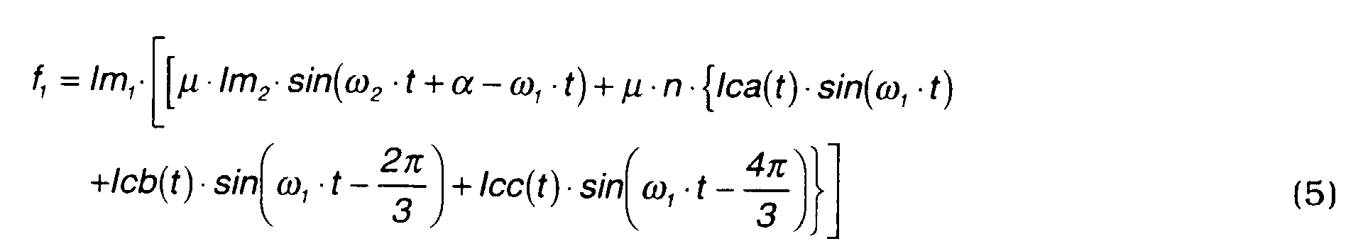
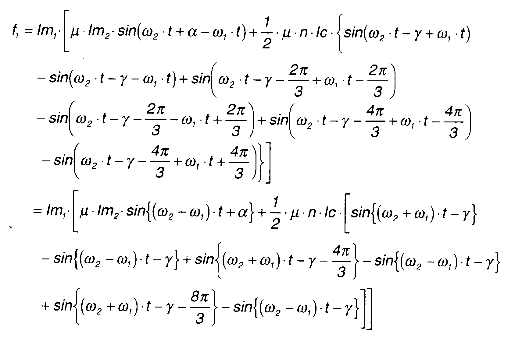
Here, let the torque acting on the outer rotor 3 be τ 1 . If the force which
acts on a semicircle of the outer rotor 3 is f1, the force which then acts the
other semicircle is also f1 . Accordingly, the force acting on the whole circumference
is 2f1, and the torque τ 1 may be expressed by the following equation.
τ 1 = 2f1·r1
where, r1 = distance to outer magnets from center shaft of outer rotor.
Here, the force f1 is a drive force which occurs when a direct current lm1 is
generated in a magnetic field of magnetic flux density B. From the above
equation, it is seen that there is a directly proportional relation between the
torque τ1 and the drive force f1. As an equivalent direct current is formed for
each semicircle, f1 is given by the following equation.
f1 = lm1·B
where,
= ω 1 ·t o .
From this equation and equation (4),
f1 may be expressed by the following
equation (5).
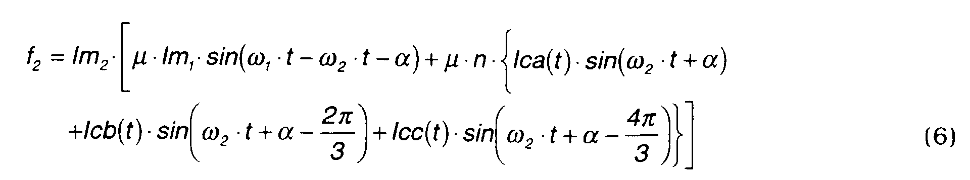
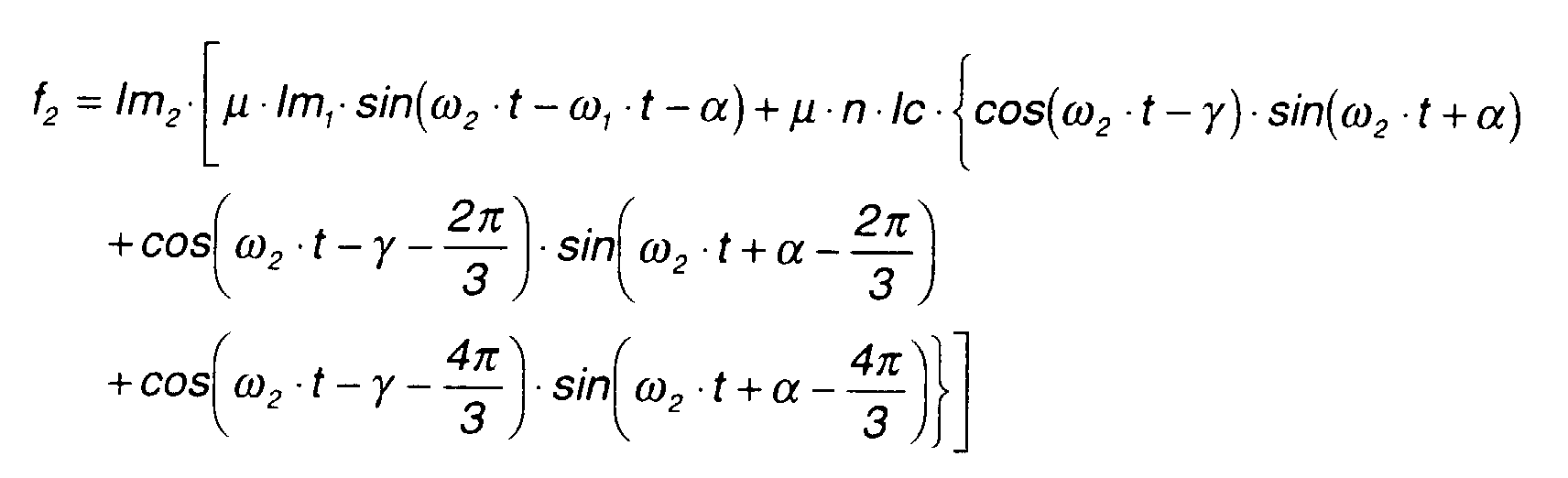
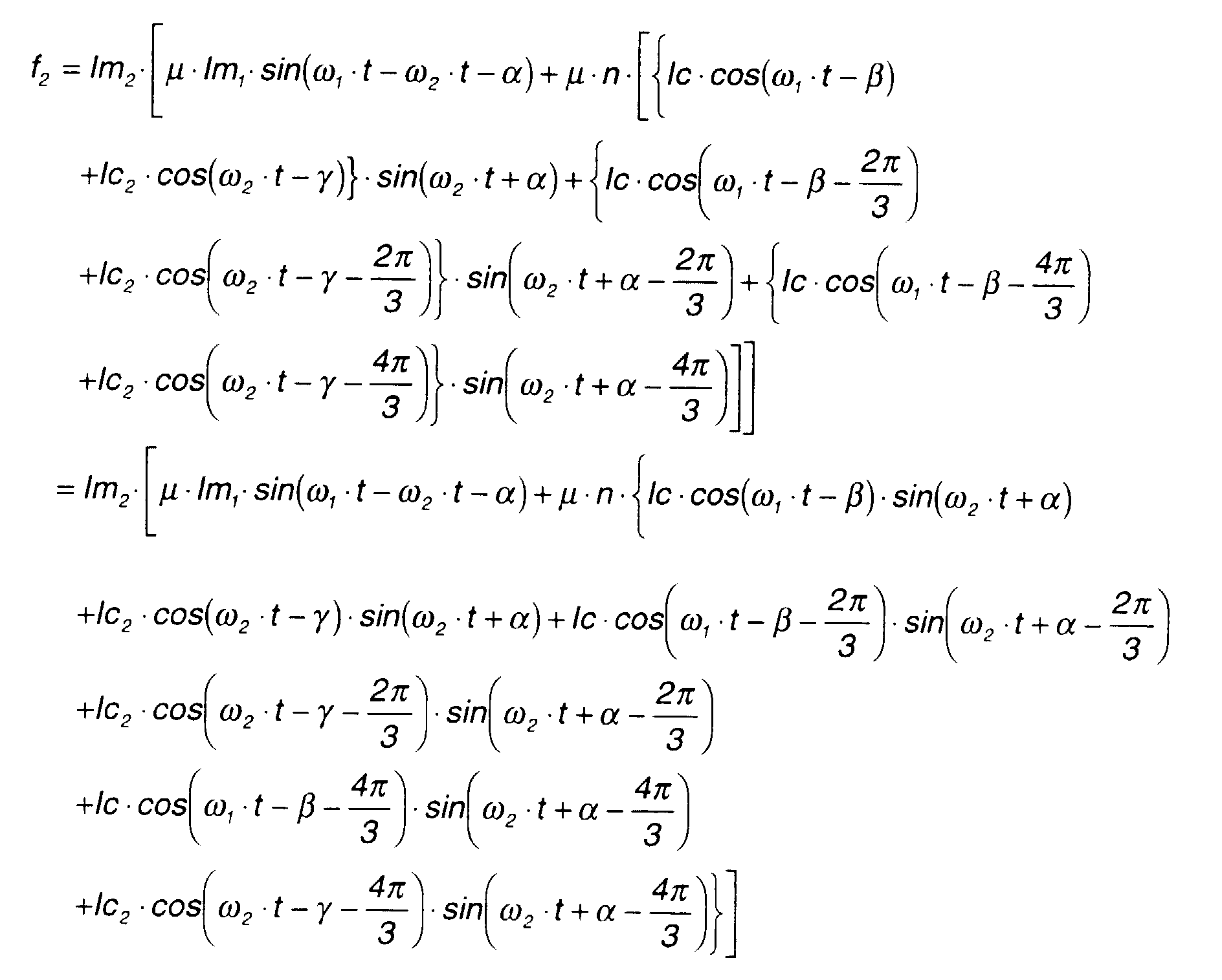
Similarly, if the force acting on the semicircle of the inner rotor 4 is f2,
the force acting on the whole rotor is 2f2 , so the torque τ 2 acting on the inner
magnets m2 may be expressed by the following equation.
τ2 = 2f2·r2
where, r2 = distance from center axis of inner rotor 4 to the inner magnets
m2 .,
Here, the force f2 is the drive force due to an equivalent direct current lm2
in a magnetic field of magnetic flux density B. As an equivalent direct current
is formed for each semicircle, f2 is given by the following equation.
f2=lm2·B
where,
=ω2 · t+α.
From this equation and equation (4),
f2 may be expressed by the following
equation (6)
In order to pass currents in the coils
a,
b, c each of which has a phase
difference of β with respect to the rotating outer magnets
m1 , alternating
currents
Ica(t), Icb(t), Icc(t) in equation (3) are set by the following equations
(7A) - (7C).
IIca(t) = Ic·cos(ω1·t - β )
where,
The drive force
f1, f2 is calculated by substituting equations (7A) - (7C) in
equations (5) - (6).
Here, the above equation may be rewritten using the formula
cos(a + b) = 1 2 ·{sin(2a + b) - sin(b)}.
Equation (8) has a form wherein the first term which is a torque fluctuation
amount due to the effect of the magnetic field of the inner agnets is added to
the second term which is a constant torque.
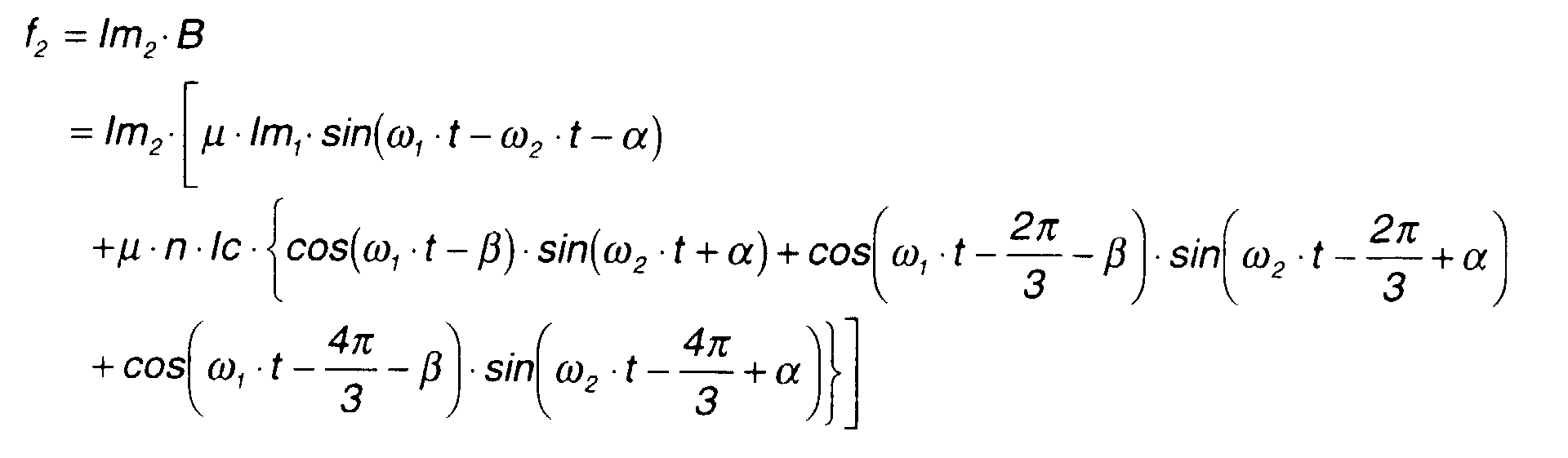
Also,
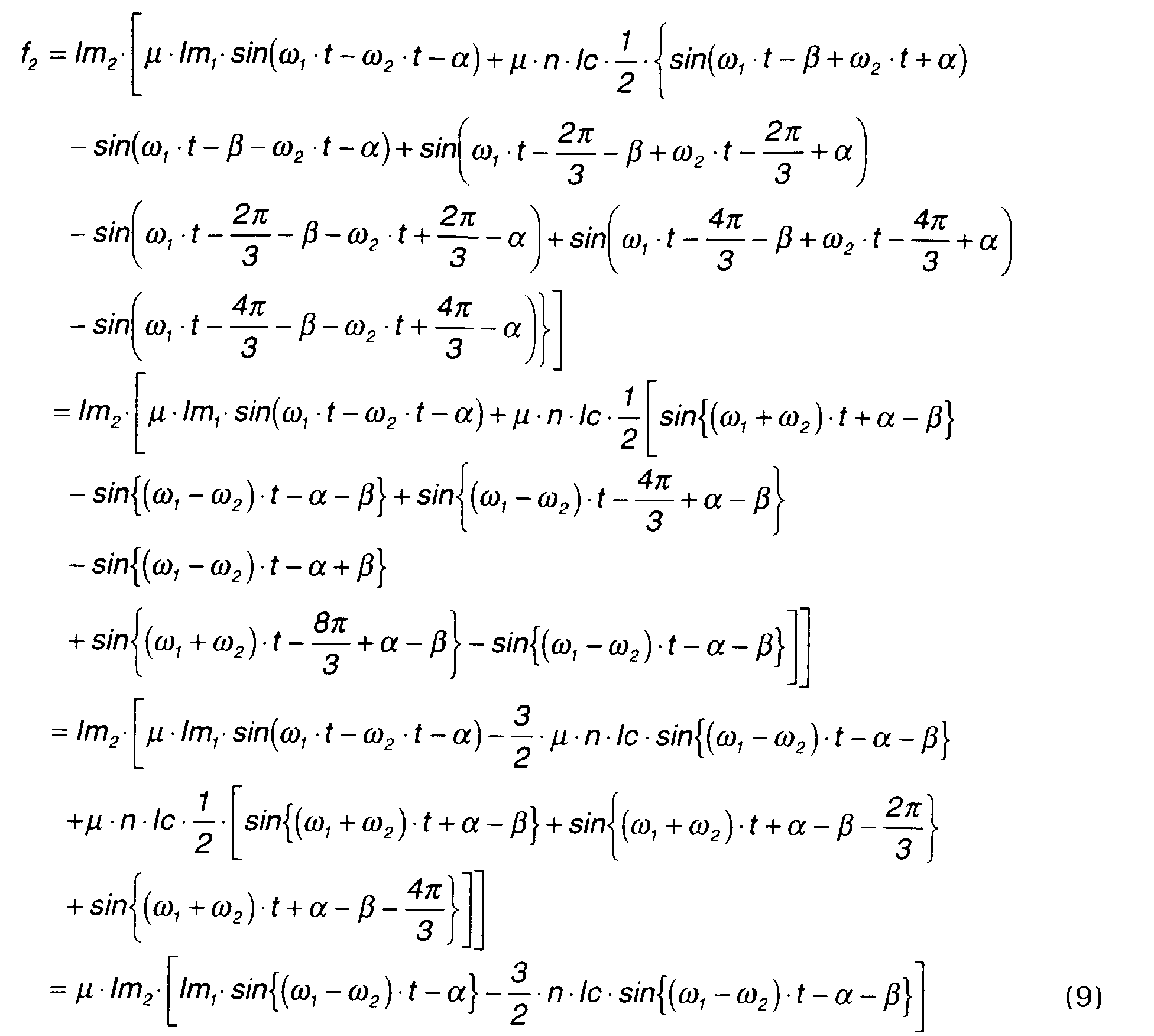
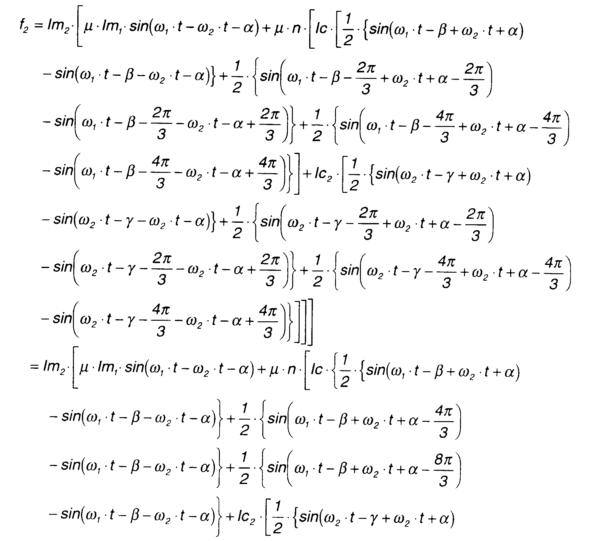
f2 may be rewritten by the following equation.
Here, the above equation may be rewritten using the formula
cos(a)·sin(b) = 1 2 ·{sin(a + b) - sin(a - b)}.
In order to pass currents in the coils
a, b, c each of which has a phase
difference of γ with respect to the rotating inner magnets
m2 , alternating
currents
Ica(t), Icb(t), Icc(t) in the above equation (3) are set by the following
equations (10A) - (10C).
IIca(t) = Ic·cos(ω 2 ·t - γ)
where,
The drive force
f1 ,
f2 is calculated by substituting equations (10A)-(10C) in
equations (5) -(6).
Here, the above equation may be rewritten using the formula
cos(a)·sin(b) = 1 2 ·{sin(a + b)- sin(a - b)}
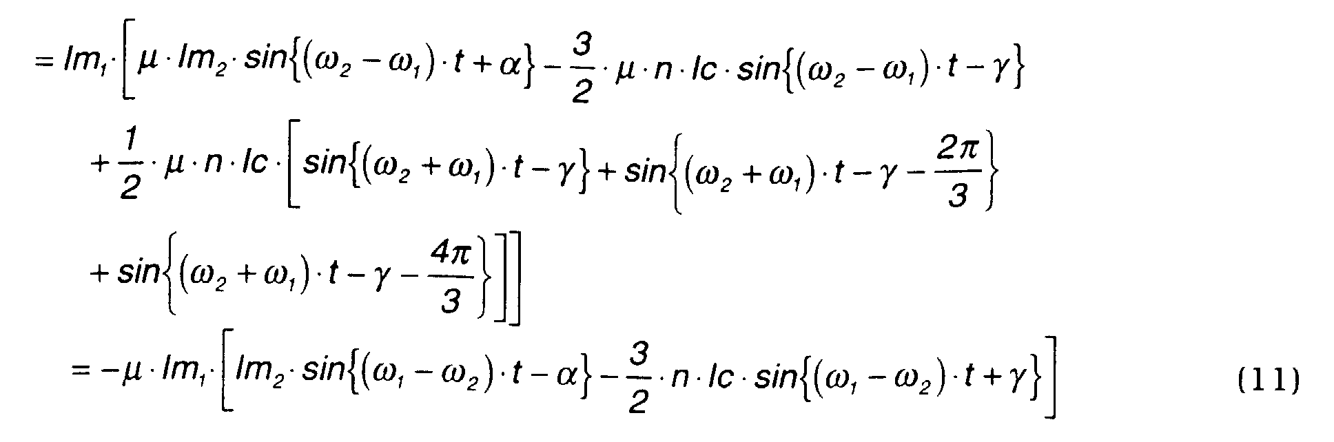
Equation (11) shows that a torque fluctuation occurs only in the outer
magnets.
Also,
f2 may be rewritten by the following equation.
Here, the above equation may be rewritten using the formula
cos(a)·sin(b) = 1 2 ·{sin(a + b) - sin(a - b)}.
Equation (12) has a form wherein the first term which is a torque fluctuation
amount due to the effect of the magnetic field of the inner magnets is added to
the second term which is a constant torque.
(1-4) When the outer rotating magnetic fields and inner rotating magnetic
fields are applied together
The above
Ica(t), Icb(t), Icc(t) are set to pass a current through the coils 6
in synchronism with the outer magnets and inner magnets.
Ica(t) = Ic·cos(ω1·t - β) + lc2·cos(ω2·t-γ)
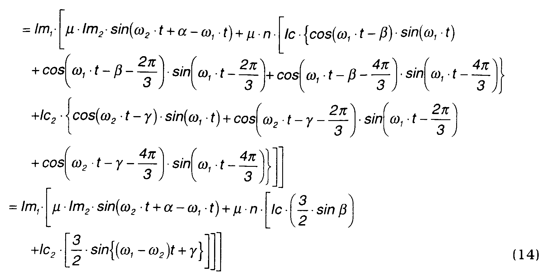
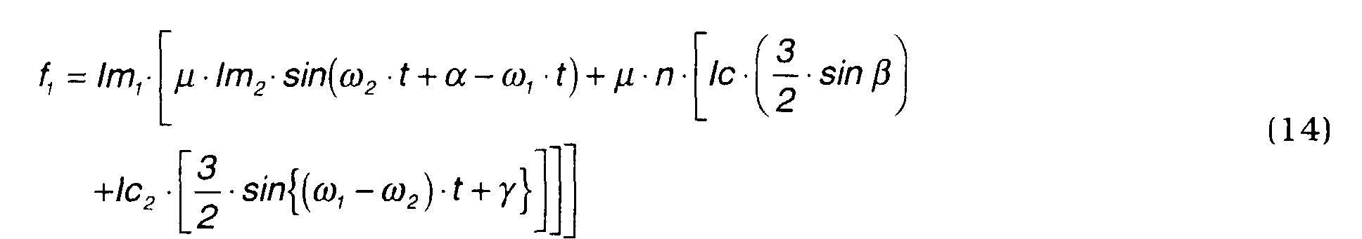
The drive forces
f1, f2 are calculated by the following equations (14), (15).
Equation (14) has a form wherein a torque fluctuation is added to a
constant torque according to a rotation phase difference β relative to the outer
magnets
m1 .
Here, the above equation may be rewritten using the formula
cos(a)·sin(b) = 1 2 ·{sin(a + b) - sin(a - b)}
Equation (15) also has a form wherein a torque fluctuation is added to a
constant torque rotation phase difference (α+γ) relative to the inner magnets
m2 .
(1-5) Summary
The above-mentioned equations (8),(9),(11),(12),(14),(15) may be
summarized as follows.
When the outer rotating magnetic fields are applied
When the inner rotating magnetic fields are applied
When the outer rotating magnetic fields and inner rotating magnetic fields are
applied together
The meaning of these equations is as follows.
The second term on the right-hand side of equation (8), the second term
on the right-hand side of equation (12), the second term on the right-hand
side of equation (14) and the third term on the right-hand side of equation
(15) are fixed terms, i.e., constant values, and a rotational torque occurs only
when these constant terms are present. Terms other than the constant terms
are trigonometric functions, and the average value of a drive force fn which
does not comprise a fixed term is zero. In other words, a rotational torque
does not occur due to terms other than fixed terms.
Comparing equations (8) and (9), only f1 from equation (8) comprises a
constant torque. In other words, when a current is passed through the coils 6
of the stator 2 in synchronism with the rotation of the outer magnets, a
rotational torque acts only the outer magnets..
Comparing equations (11) and (12), only f2 from equation (12) comprises a
constant torque. In other words, when a current is passed through the coils 6
of the stator 2 in synchronism with the rotation of the inner magnets, a
rotational torque acts only the inner magnets.
Comparing equations (14) and (15), f1 from equation (14) and f2 from
equation (15) both comprise a constant torque. In other words, when a
current synchronized with the rotation of the outer magnets and a current
synchronized with the rotation of the inner magnets are passed together
through the coils 6, rotational torques corresponding to the respective currents
act on the outer and inner magnets.
It is seen from the above facts that, when the magnetic pole number ratio
is 1:1, the two rotors 3,4 can be driven as a generator and a motor simultaneously
using only one series of coils 6. Further, it may be surmised that the same
operation is possible for any magnetic pole number ratio.
(1-6) Suppression of torque fluctuation
Due to terms other than fixed terms in the equations containing fixed
terms, i.e., due to the first term on the right-hand side of equation (8), and
the first and third terms on the right-hand side of equation (14), a torque
fluctuation appears in the outer magnets rotation due to the phase difference
(ω 1 -ω 2 ) between the inner magnets and outer magnets.
Also, due to the first term on the right-hand side of equation (12), and
the first and second terms on the right-hand side of equation (15), a torque
fluctuation appears in the inner magnets rotation due to the phase difference
(ω 1 -ω 2 ) between the inner magnets and outer magnets.
Now, the suppression of torque fluctuation will be considered when both
the outer rotating magnetic fields and an inner rotating magnetic fields are
applied.
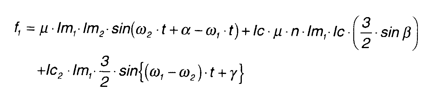
Equation (14) may be rewritten as follows.
Here,
f1 may be written as follows.
f1 = A + Ic·C + Ic2 ·V
where,
A = µ·lm1·lm2·sin(ω2·t+α-ω1·t),
V = lm1 · 3 2 ·sin{(ω 1 -ω 2 )·t+γ},
and
Here, if a modulation of Ic = C1 -A-Ic2 ·V / C is added, f1 =C1 (constant) and
the torque fluctuation is eliminated from the rotation of the outer magnets.
Similarly, equation (15) may be rewritten as follows.
f2 = µ·lm2 ·lm1 ·sin(ω 1 ·t-ω 2 ·t-α)+lc· 3 2 ·µ·lm2·n·sin{(ω1 -ω 2 )·t-α-β}
+lc2· 3 2 ·µ·lm2·n·sin(α+γ )
Here, f2 may be written as follows.
f2 = -A + lc·D + lc2 ·E
where,
D = 3 2 ·µ·lm2 ·n·sin{(ω1-ω 2 )·t-α-β},
and
E = 3 2 ·µ·lm2·n·sin(α+γ).
Here, if a modulation of lc2 = C2 + A-Ic·D / Eis added, f2 = C2 (constant) and
the torque fluctuation is eliminated from the rotation of the inner magnets.
Therefore to give both permanent magnets a constant rotation, the following
two simultaneous second order equations regarding Ic and lc2 should be solved.
C1 = A+lc·C+lc2 ·V
C2 = -A+lc·D+lc2 ·E
In this way, in the composite current, the torque fluctuation in the
rotation of the rotors can be eliminated by adding an amplitude modulation to
the alternating current which generates rotating magnetic fields that produce
a torque fluctuation.
(2) N(2(2p)-2p) Type
(2-1) When the magnetic pole number ratio is 2:1
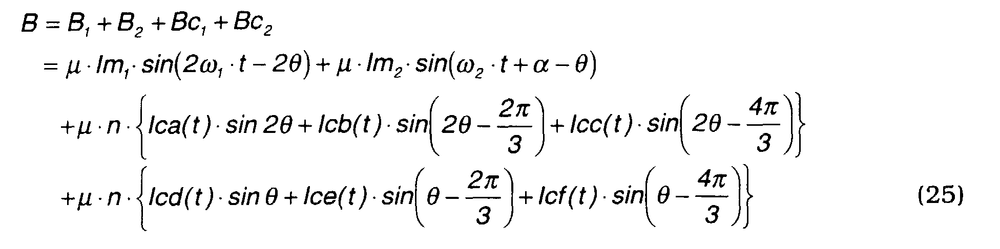
Taking the motor/generator of Fig. 9 as an example, when the magnetic
pole number of the outer magnets is 4 and the magnetic pole number of the
inner magnets is 2, the magnetic pole number ratio is 2:1. In this construction,
if the permanent magnets are magnetically replaced by an equivalent coil, a
magnetic flux density B1 generated by the outer magnets is expressed by the
following equation (21).
B1 = Bm1·sin(2ω1·t-2) = µ·lm1·sin(2ω1·t-2)
The magnetic flux density B 2 generated in the inner magnets is expressed
by equation (22) which is equivalent to the equation (2).
B2 = Bm2 ·sin(ω2·t+α-) = µ·lm2·sin(ω2·t+α-)
It may be considered that the coils are arranged as shown in Fig. 9 so as
to calculate the magnetic field produced by the coils 6 of the stator 2 separately
for the outer rotating magnetic fields which rotate the outer rotor 3 and the
inner rotating magnetic fields which rotate the inner rotor 4.
Magnetic flux densities
Bc1, Bc2 of the outer coils and inner coils are
expressed by the following equations (23), (24).
where,
lcd(
t),
lce(
t),
lcf(
t) are also currents which are different in phase by
120 degrees as in the case of
lca(
t),
lcb(
t),
Icc(
t).
Next, the change of magnetic flux density B1, B2, Bc1, Bc2 mentioned above
will be described referring to Figs. 10A - 10D.
The magnetic flux density
B at an angle _ is the sum of the aforesaid
four magnetic flux densities.
Here, if the total torque acting on the outer rotor 3 is τ1, the following
equation holds.
τ 1 = f1 ·r1
where, r1 = distance to outer magnets from center axis of outer rotor.
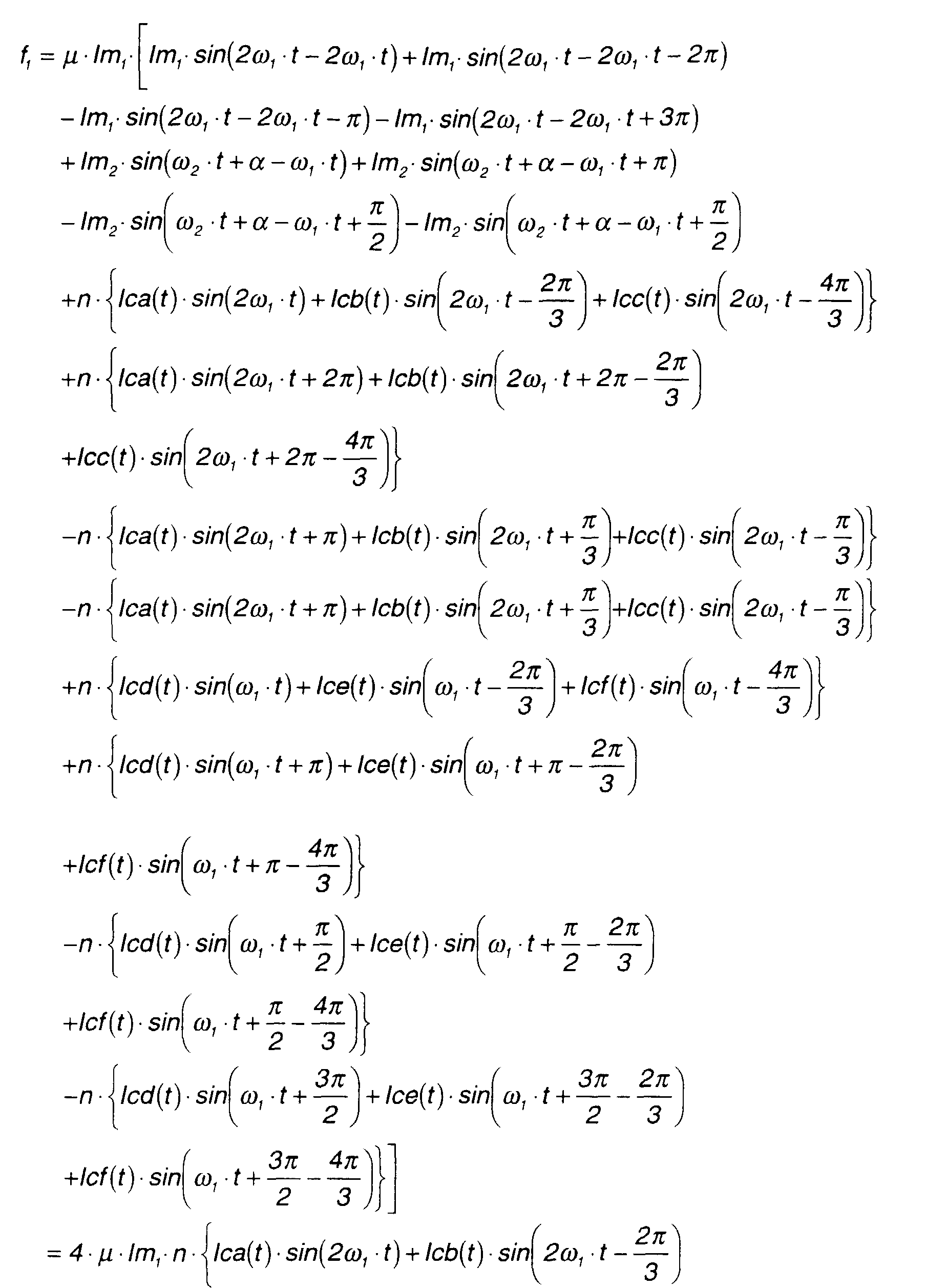
In the construction of Fig. 9, unlike the case of Fig. 7, the torques
exerted on each of the outer magnets
m1 are not symmetrical. Therefore the
force
f1 is considered to be a total force acting on each of four equivalent direct
currents that correspond to the outer magnets
m1 . This relation is expressed
by the following equation.
f1 = lm1·B10 +lm1·B20 -lm1·B30 -lm1·B40
where,
Therefore, the above equation can be rewritten as follows.
Equation (26) shows that the torque acting on the outer magnets m1 due
to the exciting currents of the coils a, b, c can be controlled, and that it is not
affected by the exciting currents of the coils d, e, f.
Next, if the torque acting on the inner rotor 4 is τ 2 , the following equation
holds.
τ2 = f2·r2
where, r2 = distance to inner magnets m2 from center shaft of an inner rotor.
The torques acting on the inner magnets
m2 of the inner rotor 4 are not
symmetrical. Therefore, the force
f2 is considered to be a total force acting on
each of two equivalent direct currents that correspond to the inner magnets.
This relation is expressed by the following equation.
f2 = lm2·B100 - lm2·B200
where,
Therefore, the above equation may be rewritten as follows.
According to the equation (27), the torque acting on the inner magnets m2
due to the excitation currents of the coils d, e, f can be controlled, and the
torque acting on the inner magnets m2 is not affected by the excitation
currents of the coils a, b, c.
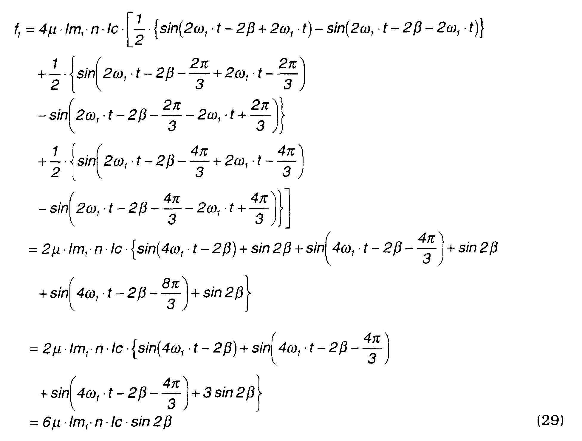
(2-2) When the outer rotating magnetic fields are applied
Currents with a phase difference of β with respect to the rotation position
of the outer magnets
m1 are passed through the coils
a, b, c. In order to
generate the above currents, the alternating currents
Ica(t), Icb(t), Icc(t) mentioned
above may be defined by the following equations.
llca(t) = lc·cos(2ω1·t-2β)
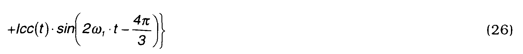
Next, (28A)-(28C) are substituted in equations (26) (27) to calculate
f1 .
Here, the above equation may be rewritten as the following equation (29)
using the formula
cos(a)·sin(b) = 1 2 ·{sin(a + b) - sin(a - b)}.
Equation (29) shows that the torque acting on the outer magnet m1 varies
according to the phase difference β. Therefore, the rotation position of the
outer magnets m1 should be measured and excitation currents shifted in phase
by β should be applied to the coils a, b, c.
(2-3) When the inner rotating magnetic fields are applied
Currents with a phase difference of γ with respect to the rotation position
of the inner magnets m2 are passed through the coils d, e, f.
In order to generate the above currents, the alternating currents
Icd(
t),
Ice
(
t),
Icf(
t) mentioned above may be defined by the following equations.
lcd(t) = lc·cos(ω 2 ·t-γ)
Next, (30A) - (30C) are substituted in equations (27) to calculate
f2.
Here, the above equation may be rewritten using the formula
cos(a)·sin(b) = 1 2 ·{sin(a + b) - sin(a - b)}
Equation (31) shows that the torque acting on the inner magnet m2 varies
according to the phase difference (γ+α).
Therefore, the rotation position of the inner magnets m2 should be measured
and excitation currents shifted in phase by (γ+α) should be applied to the coils
d, e, f.
(2-4) Summary
Equation (29) shows that when currents are passed through the coils 6 of
the stator 2 in synchronism with the outer magnets m1 , a rotational torque
acts only the outer magnets m1 .
Equation (31) shows that when currents are passed through the coils 6 in
synchronism with the outer magnets m2 , a rotational torque acts only the
outer magnets m2 .
Although the calculations are not shown, when a current synchronized
with the rotation of the outer magnets and a current synchronized with the
rotation of the inner magnets are passed together through the coils 6, rotational
torques corresponding to the respective currents act on the outer and inner
magnets as in the case where the magnetic pole number ratio is 2:1, as
described in (1-4).
This fact shows that also in the case where the magnetic pole number
ratio is 2:1, the two rotors 3, 4 can be driven as a generator /motor using the
coils 6.
In this case, as only constant terms remain, there is no fluctuation of
rotation torque of the inner rotor 4 due to the effect of the outer rotor 3 or the
rotational magnetic field produced to drive the outer rotor 3, and conversely,
there is no fluctuation of rotation torque of the outer rotor 3 due to the effect
of the inner rotor 4 or the rotational magnetic field produced to drive the
inner rotor 4.
In other words, when the magnetic pole number ratio is 2:1, both rotors
can be driven with a constant rotation, without adding an amplitude modulation
to eliminate torque fluctuation as when the magnetic pole number ratio is
1:1, or as described later, 3:1.
(2-5) Setting of currents flowing through stator coil
In Fig. 9, a series of coils a, c, b for generating the outer rotating
magnetic fields and another series of coils d, f, e for generating the inner
rotating magnetic fields are assumed for the purpose of theoretical calculation.
In the real motor/generator according to this invention, these coils are
integrated as shown in Fig. 11. specifically, the coils a and d, b and f, c and e,
a and d, b and f, and c and e in Fig. 9 are respectively integrated to coils #1,
#3, #5, #7, #9, #11. The composite currents l1 - l12 passed through the coils #1
-#12 in Fig. 11 are therefore set as follows due to their relation to the currents
passed through the coils a, c, b and d, f,e in Fig. 9.
l1 = la +ld
l2 = lc
l3 = lb + lf
l4 = la
l5 = lc + le
l6 = lb
l7 = la + ld
l8 = lc
l9 = lb + lf
l10 = la
I11 = lc + le
l12 = lb
In this case, the load on the coils through which the currents l1 , l3 , l5 , l7 ,
l9 , l11 are passed is greater than that of the remaining coils through which the
currents l2 , l4, l6, l8, l10 are passed. Therefore, it is considered to spread the load
among the remaining coils in order to form the inner rotating magnetic fields.
For example, comparing Fig. 2 and Fig. 1, the coils in Fig. 2 corresponding
to 1, 1, 2, 2 in Fig. 1 are the outer coils a, a , c, c and the inner coils d, d. In
this case, it is assumed that the position of the coils d, d is shifted to a
position that is equidistant from the coil a, a and the coil c , c. These shifted
coils are designated as coils d', d'.
Half of the current ld' passed through the coil d' is assigned to each of
the coils a and c , and half of the current Id ' passed through the coil d' is
assigned to each of the coils a and c. Similarly coils e', e' and f', f' are
assumed and the currents passing through these coils are allocated in a
similar manner.
In this way, the following alternative current settings are possible:
l1 = la + 1 2 ·Id'
l2 = Ic + 1 2 ·Id'
l3 = lb + 1 2 ·If
l4 = la + 1 2 · If
l5 = lc + 1 2 ·le'
l6 = lb + 1 2 ·le'
l7 = la + 1 2 · ld'
l8 = lc + 1 2 · ld'
l9 = lb + 1 2 ·lf
l10 = la + 1 2 ·lf
I11 = lc + 1 2 · le '
l12 = lb + 1 2 · le'
Alternatively, the following settings are possible.
l1 = la +li
l2 = lc +lii
l3 = lb +liii
l4 = la +liv
l5 = lc +lv
l6 = lb +lvi
l7 = la +Ivii
I8 = lc +Iviii
I9 = lb +lix
l10 = la +lX
I11 = lc +lXi
l12 = lb +lxii
The currents li - lxii which are the second terms on the right-hand side of
the above equations for setting l1 - l12, comprise a twelve-phase alternating
current as shown in Fig. 12A, 12B. The inner rotating magnetic fields may be
formed by this twelve-phase alternating current.
(2-6) When the inner rotating magnetic fields are supplied by twelve-phase
alternating current
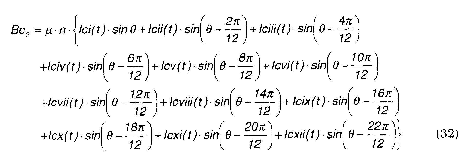
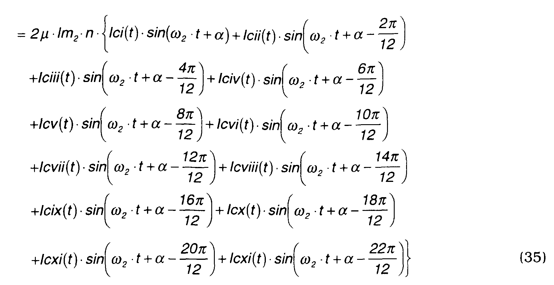
(2-6-1) Magnetic flux density Bc2
The magnetic flux density
Bc2 when the inner rotating magnetic fields are
supplied by a twelve-phase alternating current is expressed by the following
equation (32).
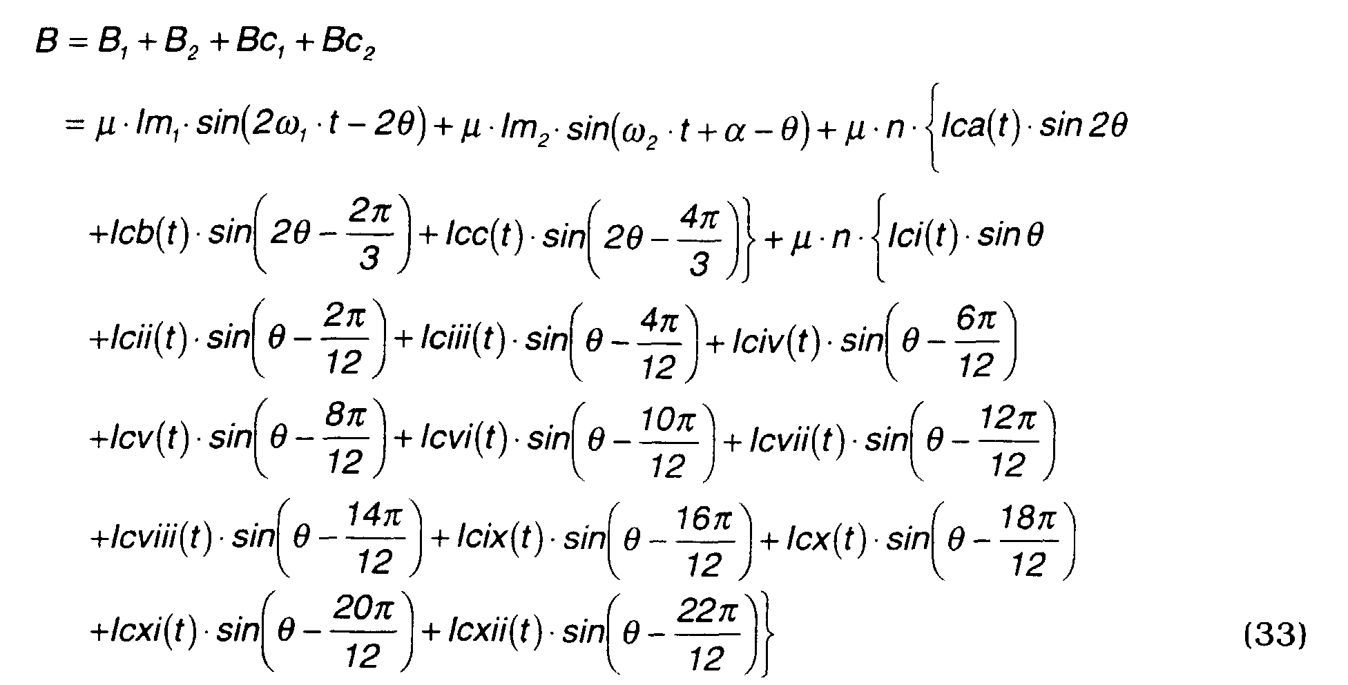
The total magnetic flux density
B is expressed by the following equation.
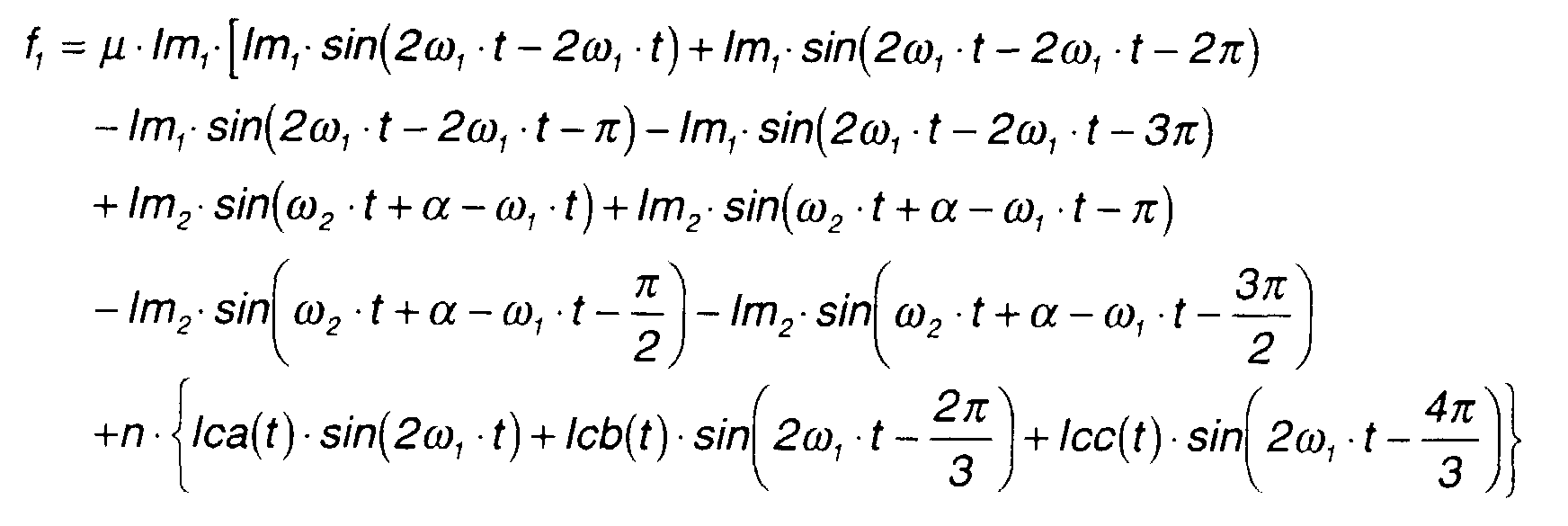
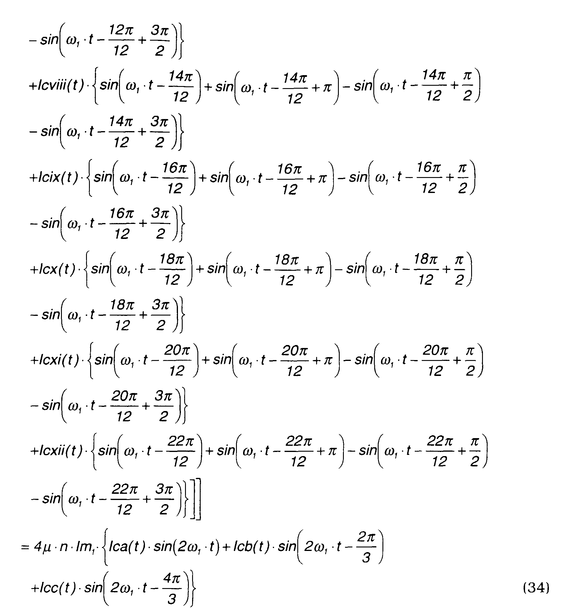
f1 is calculated by the following equation.
f1 = lm1·B10 + lm1·B20 - lm1·B30 - lm1·B40
where,
Therefore, the above equation can be rewritten as follows.
This is the same as equation (26) where the inner rotating magnetic fields
are produced by a three-phase alternating current.
Also,
f2 is calculated by the following equation.
f2 = lm2·B100 - lm2·B200
where,
Therefore, the above equation can be rewritten as follows.
f2 given by this equation (35) is different from
f2 given by equation (27)
when the inner rotating magnetic fields are formed by a three-phase alternating
current. Therefore, the following calculation of
f2 when the inner rotating
magnetic fields are formed by a twelve-phase alternating current, will be
performed.
The above-mentioned twelve-phase alternating current
lci(
t)-
lcxii(
t) is set
by the following equations (36A) - (36L).
lci(t) = lc2 (t)·cos(ω2·t-γ)
f2 is calculated by substituting equations (36A) - (36L) in equation (35).
Here, the above equation may be rewritten using the formula
cos(a)·sin(b) = 1 2 ·{sin(a + b) - sin(a - b)}.
Comparing equation (37) obtained when the inner rotating magnetic fields
are supplied by a twelve-phase alternating current with the above-mentioned
equation (31) obtained when the inner rotating magnetic fields are supplied by
a three-phase alternating current (31), the constant term of equation (37), i.e.,
the last term, is four times that of equation (31).
In other words, when the inner magnet is driven by a twelve-phase
alternating current (li - lxii), the drive torque obtained is four times that when
the inner magnet is driven by a three-phase alternating current.
In other words, the inner magnets drive current required to exert the
same drive torque on the inner *magnets m2 , is only one fourth of that when a
three-phase alternating current is applied.
(3) N(3(2p)-2p) type
(3-1) When the magnetic pole number ratio is 3:1
Taking a motor/generator of Fig. 13 as an example, the magnetic pole
number ratio is 3:1 when the magnetic pole number of the outer magnets m2 is
6 and the magnetic pole number of the inner magnets m1 is 2.
In this construction, the magnetic flux densities B1 and B2 generated by
the outer and inner permanent magnets are expressed by the following equations
(41), (42).
B1 = Bm1 ·sin(3ω 1 ·t-3) = µ·lm1 ·sin(3ω 1 ·t-3)
B2 = Bm2 ·sin(ω2·t+α-) = µ·lm2·sin(ω2·t+α-)
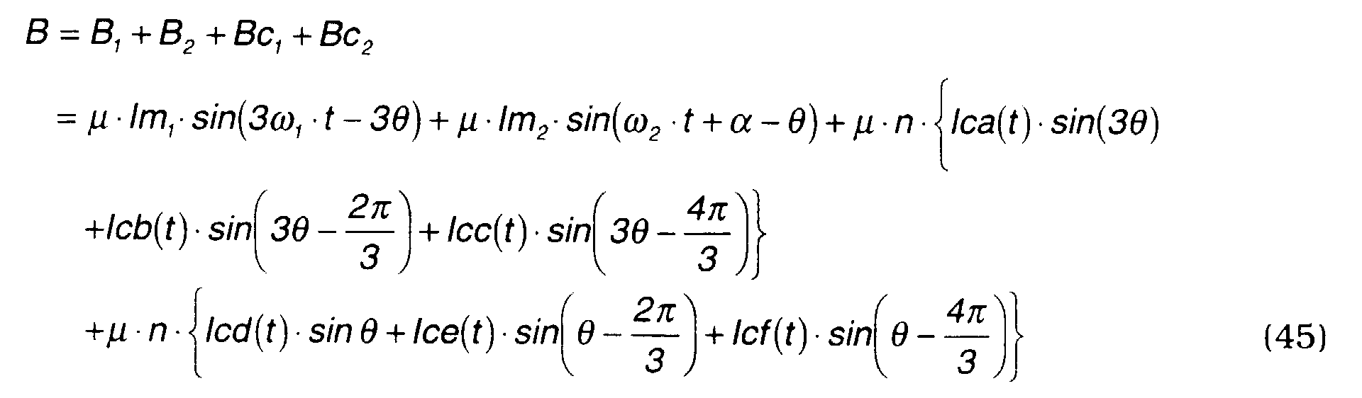
The rotating magnetic fields produced by the coils 6 of the stator 2 are
calculated separately for the outer rotor 3 and inner rotor 4. The magnetic
flux densities
Bc1, Bc2 of the coils 6 relative to the outer magnets
m1 and inner
magnets
m2 are expressed by the following equations (43), (44).
The variation of the aforesaid magnetic flux densities B1, B2 and Bc, Bc2
are shown in Figs. 14A - 14D.
The total magnetic flux density
B is expressed by the following equation.
Here, let the torque acting on the outer rotor 3 be τ 1 . If the force which
acts on a semicircle of the outer rotor 3 is f1 , the force which then acts on the
other semicircle is also f1 . Therefore, the force acting on the whole circumference
is 2f1, and the torque τ 1 may be expressed by the following equation.
τ 1 = 2f1·r1
where, r1 = distance to outer magnets from center axis of outer rotor.
As three equivalent direct currents are formed for one semicircle,
f1 is
given by the following equation.
f1 = lm1 ·B1000 + lm1 ·B2000 - lm1 ·B3000
where,
Therefore, the above equation can be rewritten as follows.
Equation (46) shows that when the magnetic flux density of the outer
magnets m1 is approximated to a sine wave, the torque acting on the outer
magnets m1 can be controlled by the exciting currents of the coils a, b, c.
It also shows that the torque acting on the outer magnets m1 is not
affected by the excitation currents of the coils d, e, f.
Here, let the torque acting on the inner rotor 4 be τ 2 . If the force which
acts on a semicircle of the inner rotor 4 is f2 , the force which then acts the
other semicircle is also f2 . Therefore, the force acting on the whole circumference
is 2f2 , and the torque τ 2 may be expressed by the following equation.
τ 2 = 2f2 · r2
where, r2 = distance from center axis of inner rotor 4 to inner magnets m2 .
Here, the force f2 is a drive force which an equivalent direct current lm2
generates in a magnetic field of magnetic flux density B. As an equivalent
direct current is formed for each semicircle, f2 is given by the following equation.
f2 = lm2·B
where, = ω 2 ·t+α.
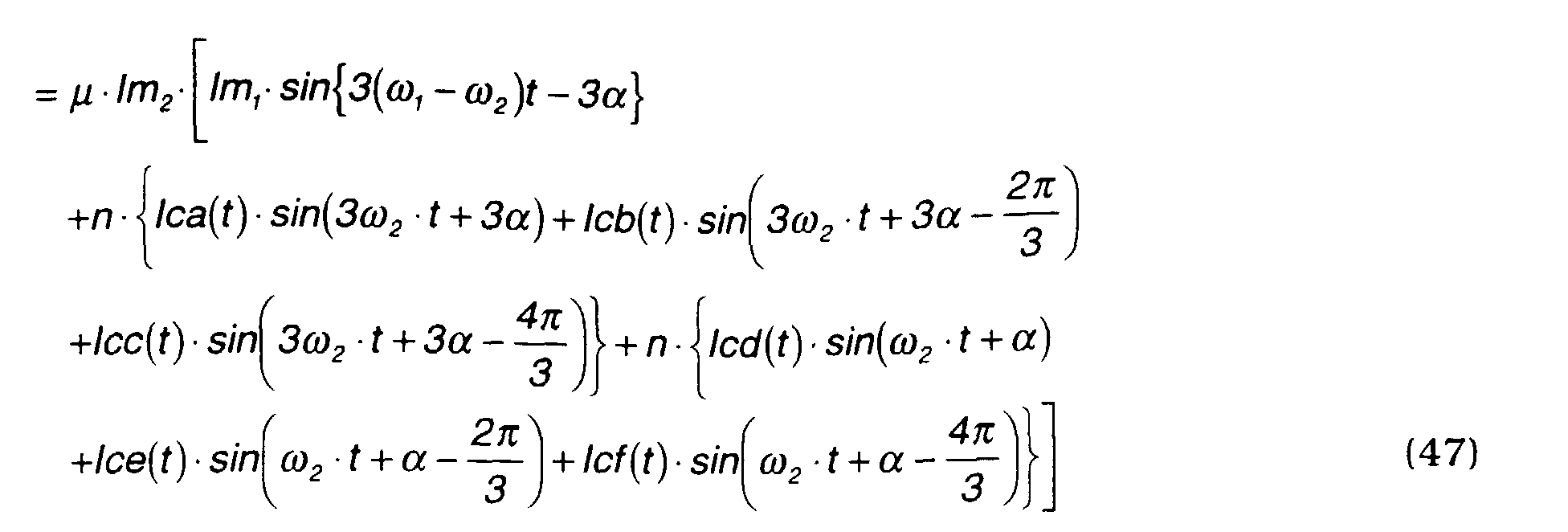
From this equation and equation (45),
f2 may be expressed by the following
equation (47).
The second term in equation (47) shows that the torque acting on the
inner magnets m2 is evidently affected by the exciting currents of the coils a, b,
c for the outer magnets m1 . However, this is an apparent effect, and there is
actually no effect due to the following reason.
If the positions of the outer magnets
m1 are
1 = ω
1 ·
t + π/
6,
2 =
ω1 ·
t +
5π/
6,
3 =
ω1 ·
t +
9π/6 respectively, the magnetic flux density
B1 of the outer magnets
m1 at a rotation angle may be expressed by the following equation.
This shows that the magnetic poles formed at 120 degree intervals cancel
the magnetic force. In other words, the magnetic pole number of the outer
magnets
m1 has no effect on the inner magnets
m2 . Similarly, the magnetic
flux density produced by the outer coil is also 0 in total. Therefore, the drive
force
f2 is as follows.
The alternating currents
Ica(t), Icb(t), Icc(t) and alternating currents
Icd(
t),
Ice(
t),
Icf(
t) are expressed by the following equations.
Ica(t) = lc1·cos(3ω1·t - 3β)
Icd(t) = Ic2 (t)·cos(ω 2 ·t - γ)
In equations (50A) - (50C), to permit amplitude modulation, the current
is assumed to be Ic2 (t) which is a function of time t.
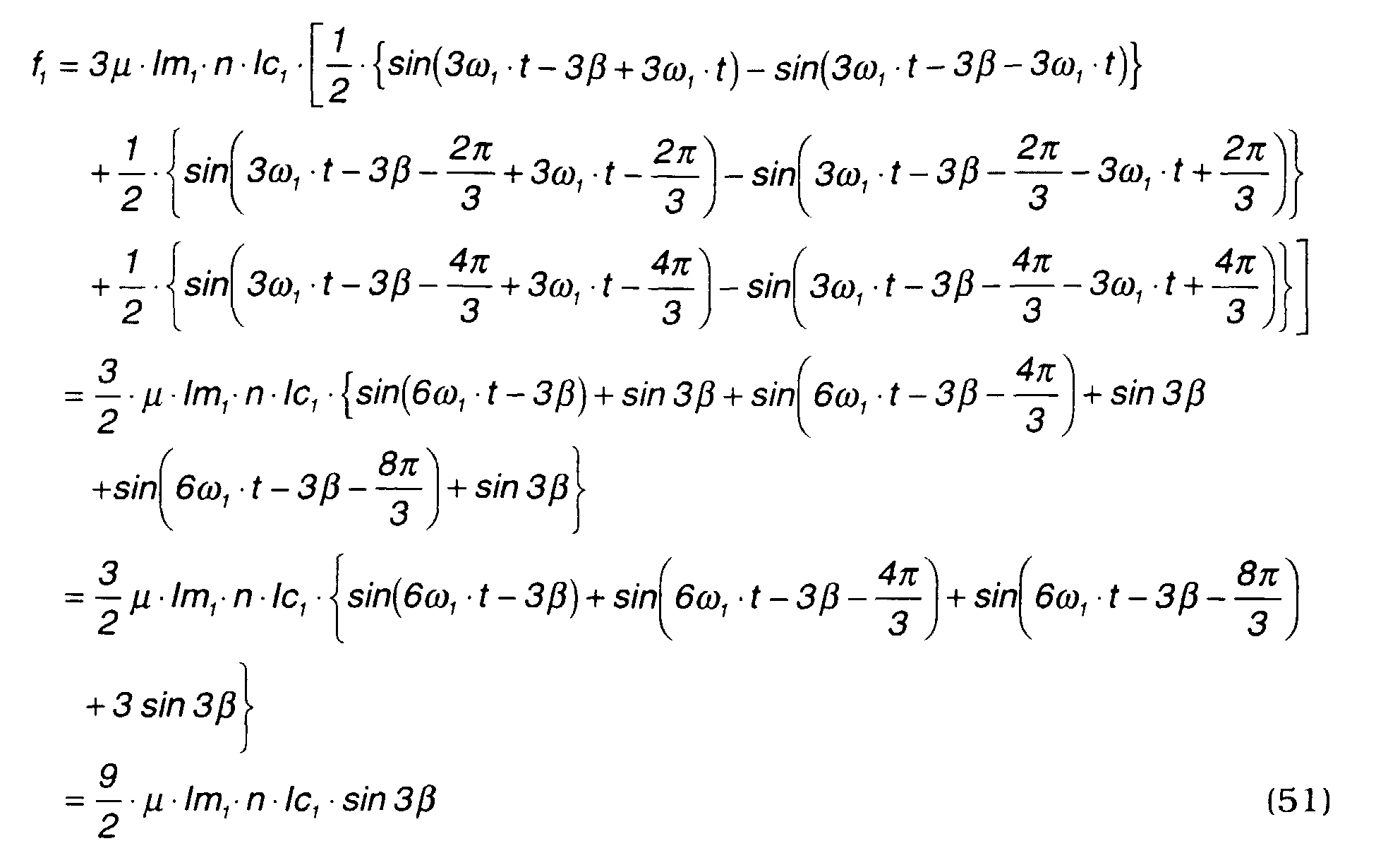
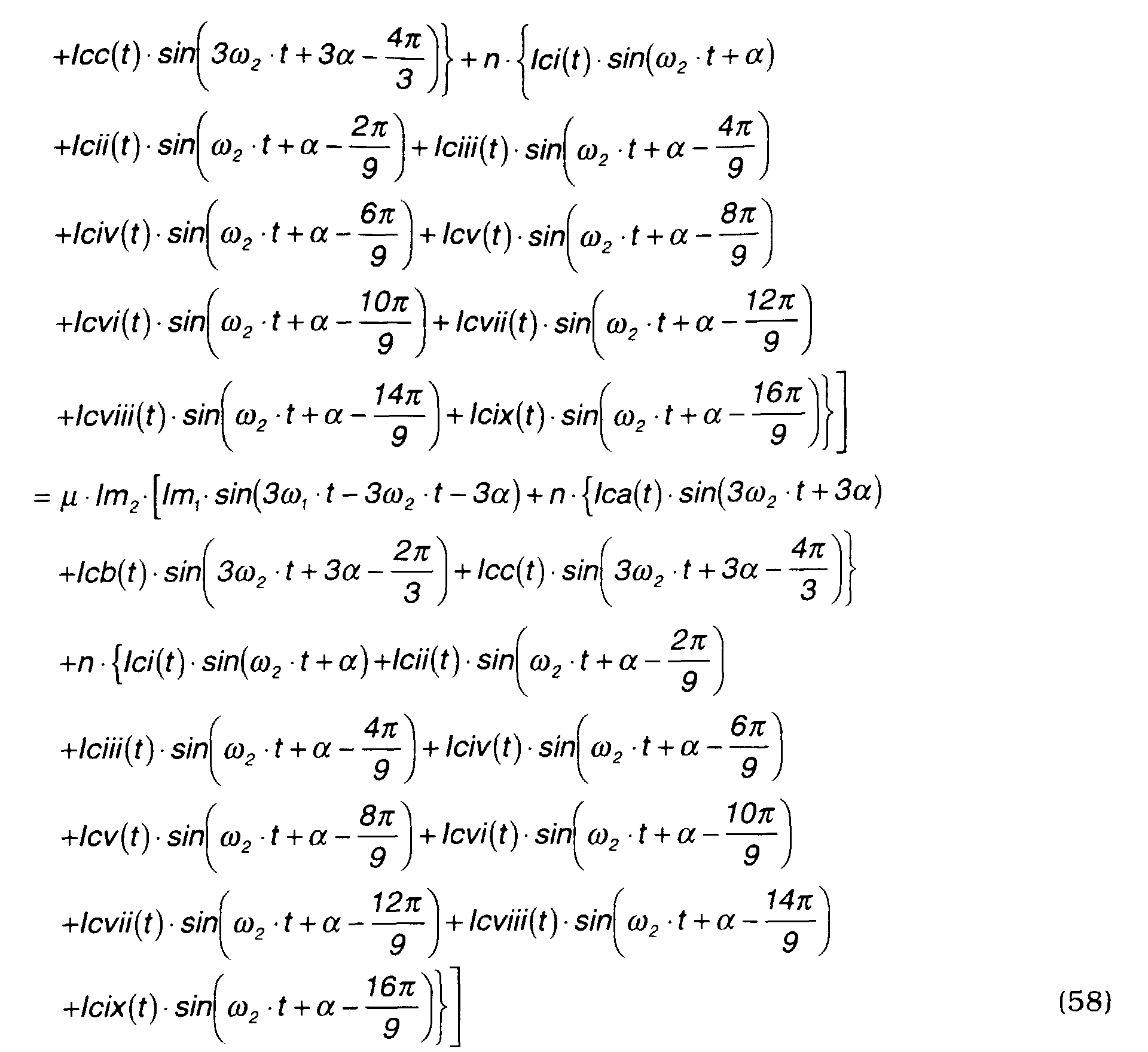
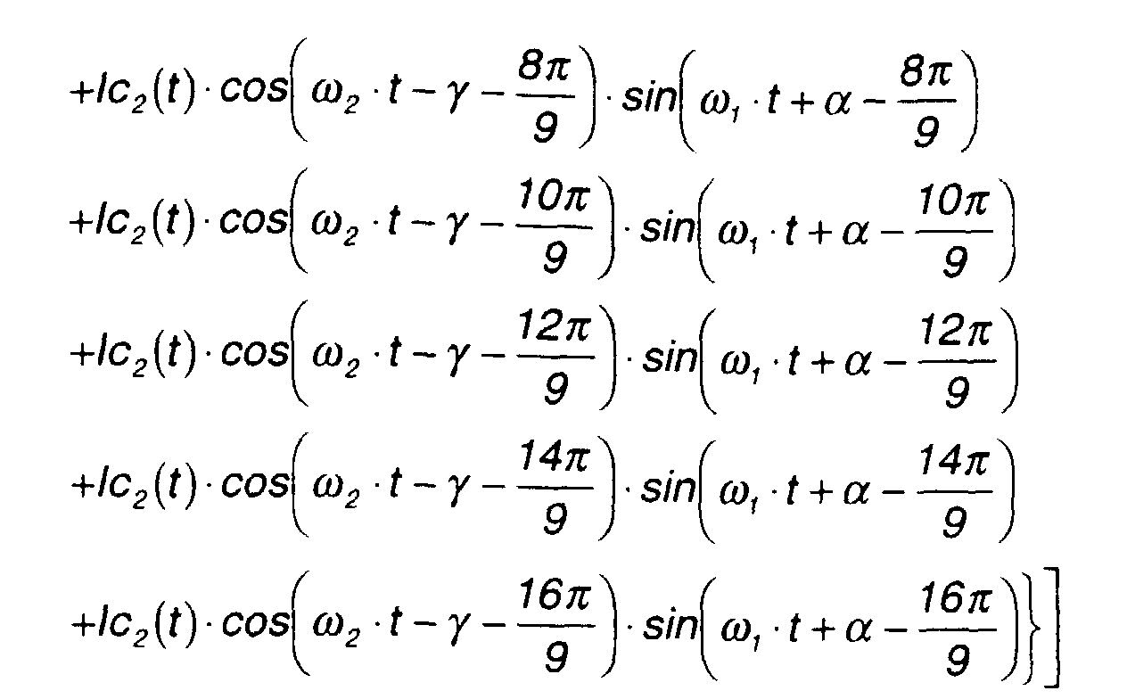
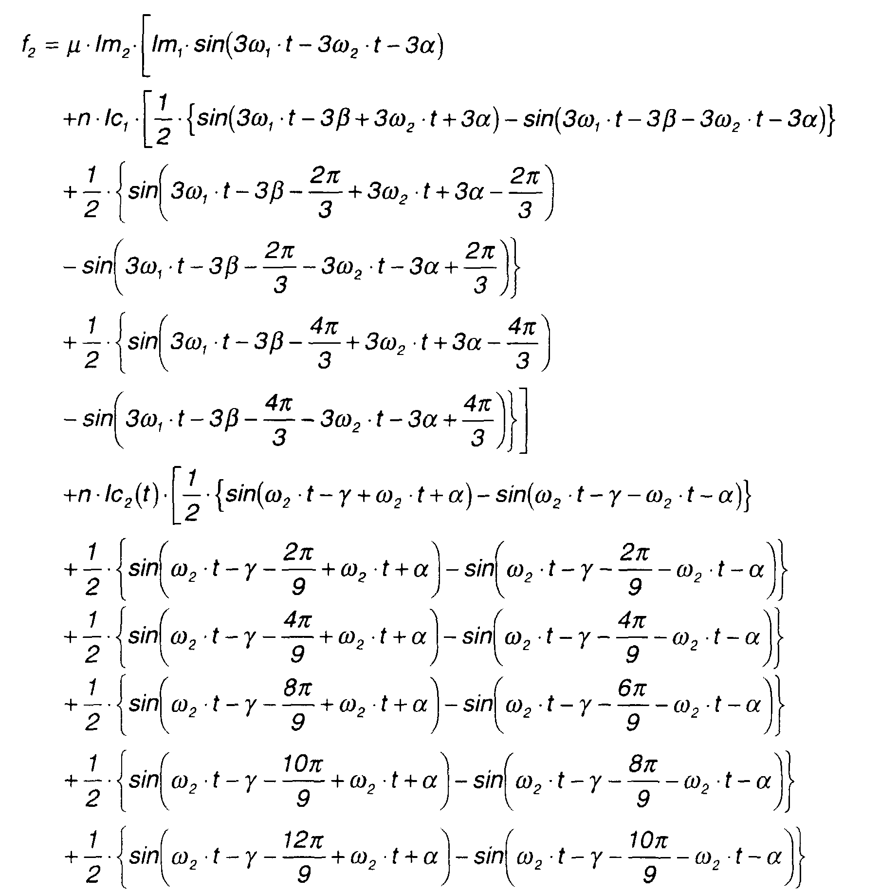
f1, f2 are calculated by substituting equations (49A) - (49C) in equation
(46), and substituting equations (49A) - (49C) and (50A) - (50C) in equation
(47).
Here, the above equation may be rewritten using the formula
cos(a)·sin(b) = 1 2 ·{sin(a + b) - sin(a - b)}.
Here, the above equation may be rewritten using the expression
cos(a)·sin(b) = 1 2 ·{sin(a + b) - sin(a - b)}.
As described with regard to equation (48), f2 is a constant value when
there is no effect of the outer magnets m1 and outer coils a, c, b as shown by
the following equation (53).
f2 = 3 2 ·{n·lc2 (t)·sin(γ + α)}
Conversely, when there is an effect from the magnetic field due to the
outer magnets m1 and outer coils, if lc2 (t) is set by the following equation (54),
ff2 =C (constant) in the equation (52) and the motor/generator can be driven
by a constant torque.
Ic2 (t) = 2 3 · C µ·Im 2 -Im1 ·sin 3(ω 1 -ω 2 )t - 3α + n·Ic1 ·sin(3ω 1 ·t - 3β-3ω 2 ·t - 3α) n·sin γ+α
In other words, this means that according to equation (52), some effect of
the outer magnets m1 is generated relative to the rotation of the inner magnets
m2 when the magnetic pole number ratio is 3:1. More precisely, a constant
torque fluctuation based on the phase difference (ω 1 - ω 2 ) occurs in the
rotational torque of the inner magnets m2 . This situation is shown in Figs.
15A - 15C.
If a magnetic field is assumed to be rectangular in a model representation,
the magnetic force interference between the outer magnets and inner magnets
may be clearly expressed.
Comparing state A with state B, as state B is stable, a torque is generated
in state A which tends to shift to state B. This torque is an intermittent
torque and is generated by a phase difference (ω 1 - ω 2 ). Further, as a perfect
sine wave cannot be realized due to the effect of distance between coils, it may
be impossible to completely eliminate the effect of the outer magnets. The
most extreme example of such case is expressed by equation (52). However, a
torque fluctuation can be eliminated in most cases by applying amplitude
modulation from equation (54), and the inner magnet can be driven with a
constant torque even when the magnetic pole number ratio is 3:1.
(3-3) Summary
According to equations (51), (52), when currents are passed through the
coils of the stator 2 in synchronism with the rotations of the outer magnets
m1 and inner magnets m2 , a rotational torque acts on both permanent magnets.
It will of course be understood that when currents are passed through the
coils of the stator in synchronism with the rotation of the outer magnets m1, a
rotational torque acts only the outer magnets m1, and when currents are
passed through the coils of the stator in synchronism with the rotation of the
inner magnets m2 , a rotational torque acts only the inner magnets m2 .
This fact shows that also in the case where the magnetic pole number
ratio is 3:1, the two rotors 3, 4 can be driven as a generator and a motor using
one series of the coils 6.
(3-4) Current settings
In Fig. 13, one series of coils a, c, b are assumed to generate the outer
rotating magnetic fields, and another series of coils d, f, e are assumed to
generate the inner rotating magnetic fields.
In the real motor/generator according to this invention, these coils are
integrated as shown in Fig. 16. Specifically, the coils a and d, a and f, a and
e, a and d, a and f, a and e in Fig. 13 are respectively integrated to coils #1,
#4, #7, #1, #4 and #7.
In view of the construction of Fig. 16, the currents passing through the
coils 6 of the stator 2 may be set as follows.
| I1 = Ia +Id | I10 = I1 = Ia + Id |
| I2 = lc | I11 = I2 = lc |
| I3 = lb | I12 = I3 = Ib |
| I4 = Ia + If | l13 = I4 = la + If |
| I5 = lc | I14 = l5 = lc |
| l6 = lb | I15 = l6 = Ib |
| l7 = la +le | l16 = la + le |
| l8 = lc | l17 = l8 = lc |
| l9 = lb | l18 = l9 = lb |
When the magnetic pole number ratio is 3:1, an eighteen-phase alternating
current is required, but the phase is reversed over half the circumference, so a
nine-phase alternating current (half of eighteen-phase) may be used.
In this case as the load on coils #1, #4, #7, #
1, #
4 and #
7 is heavy, it is
desirable to use also the remaining coils in order to form the inner rotating
magnetic fields. For example, the following current settings are recommended.
| l1=la + li | l10=l1 =la + li |
| l2=lc + lvi | l11=l2 =lc + lvi |
| l3=lb + lii | l12 = l3 =lb + lii |
| l4=la + Ivii | I13=l4=Ia+Ivii |
| l5=lc + liii | l14=l5 =lc + liii |
| l6=lb + lviii | l15 = l6 =lb + lviii |
| l7 =la +liv | l16 =l7 =la + liv |
| l8=lc + lix | l17=l8=lc + lix |
| l9=lb + lv | l18=l9=lb + Iv |
The phases of the currents li - lix and li - lix for forming the inner rotating
magnetic fields are shown in Figs. 17A and 17B.
(3-5) When the inner rotating magnetic fields with nine-phase alternating
current are supplied
(3-5-1) Magnetic flux density Bc2
The magnetic flux density
Bc2 when the inner rotating magnetic fields are
produced by nine-phase alternating current is expressed by the following equation
(55).
The total magnetic flux density
B is expressed as follows.
f1 is calculated by the following equation.
f1 = lm1·B1000 + lm1·B2000 - lm1·B3000
where,
Therefore, the above equation can be rewritten as follows.
This is the same as equation (46) which is obtained when the inner
rotating magnetic fields are supplied by a three-phase alternating current.
On the other hand, f2 may be calculated as follows.
f2 = lm2·B
where, = ω2·t+α.
From this equation and equation (56),
f2 may be expressed by the following
equation.
The three-phase alternating currents
Ica(t), Icb(t), Icc(t) mentioned above
are expressed by the following equations (59A), (59B), (59C).
Ica(t)) = lc1·cos(3ω1·t-3β)
The nine-phase alternating currents
lci(
t)-
lcix(
t) mentioned above are set
as follows.
IIci(t) = lc2 (t)·cos(ω2 ·t-γ)
Next,
f2 is calculated by substituting equations (59A) - (59C) and equations
(60A) - (60I) into equation (58).
Here, the above equation may be rewritten using the formula
cos(a)·sin(b) = 1 2 ·{sin(a + b) - sin(a - b)}.
As described in the case of equation (48), as in the case of three-phase
alternating current, the first and second terms on the right-hand side of
equation (61) are canceled when these terms in other phases are taken into
account.
When this equation (61) for the case where the inner rotating magnetic
fields are supplied by a nine-phase alternating current is compared with the
above-mentioned equation (52) where the inner rotating magnetic fields are
supplied by a three-phase alternating current, the fixed term of equation (61),
i.e., the last term, is three times that of equation (52).
In other words, when the drive current of the inner magnets m2 is a
nine-phase alternating current (li - lix), a drive force, i.e., drive torque, is three
times that when the drive current of the inner magnet is a three-phase
alternating current.
In other words, the drive torque required to generate the same drive
torque for the inner magnets m2 is only 1/3.
This completes the theoretical analysis of this invention.
Finally, fourth-eighth embodiments of the invention will be described
referring to Figs. 18 - 22. Here too, the inner rotor 4 is arranged inside the
stator 2 and the outer rotor 3 is arranged outside the stator 2 as in the
above-mentioned first-third embodiments, and the magnetic pole number ratio
of the outer rotor 3 and inner rotor 4 is varied.
In the fourth embodiment shown in Fig. 18, the magnetic pole number
ratio is set at 2:1.
In the fifth embodiment shown in Fig. 19, the magnetic pole number ratio
is set at 2:1.
In the sixth embodiment shown in Fig. 20, the magnetic pole number
ratio is set at 3:1.
In the seventh embodiment shown in Fig. 21, the magnetic pole number
ratio is set at 9:1.
In the eighth embodiment shown in Fig. 22, the magnetic pole number
ratio is set at 3:1.
Hence, this invention may be applied when the magnetic pole number of
the outer rotor 3 is less than or greater than the magnetic pole number of the
inner rotor 4.
In Figs. 18 - 22, several salient poles are not shown, but the ratio of
outer salient pole number to inner salient pole number is set to be the same
as the magnetic pole number ratio of the outer rotor 3 and inner rotor 4.
Specifically, it is set at 2:1 in the fourth embodiment shown in Fig. 18 and
fifth embodiment shown in Fig. 19. It is set at 3:1 in the sixth embodiment
shown in Fig. 20 and eighth embodiment shown in Fig. 22. In the seventh
embodiment shown in Fig. 21, it is set at 9:1.
In the description of the above embodiments, the case was described
where the rotors were driven as a motor, however they may of course also be
used as generators, or one rotor may be used as a motor and the other one
may be used as a generator to generate power.
The contents of Tokugan Hei 10-77465, with a filing date of March 25,
1998 in Japan, are hereby incorporated by reference. Although the invention
has been described above by reference to certain embodiments of the invention,
the invention is not limited to the embodiments described above. Modifications
and variations of the embodiments described above will occur to those skilled
in the art, in light of the above teachings.
For example, in the above embodiments, the rotors 3 and 4 were arranged
outside and inside the stator 2, but both rotors may be arranged outside the
stator 2 or inside the stator 2.
Also, the signal output by the control circuit 15 to the inverter is not
limited to a PWM signal, and a pulse amplitude modulation (PAM) signal or
other signals may be used.
This invention is not limited to a radial gap type motor/generator wherein
the gap between the rotor and the stator is set in a radial direction, and may
be applied to a motor/generator wherein the gap between the rotor and stator
is in an axial direction.
The embodiments of this invention in which an exclusive property or
privilege is claimed are defined as follows: