EP0947217A2 - Appareil pour la suppression de déviations produites par des perturbations externes dans des signaux internes, mesurés dans un stimulateur cardiaque implantable - Google Patents
Appareil pour la suppression de déviations produites par des perturbations externes dans des signaux internes, mesurés dans un stimulateur cardiaque implantable Download PDFInfo
- Publication number
- EP0947217A2 EP0947217A2 EP98121828A EP98121828A EP0947217A2 EP 0947217 A2 EP0947217 A2 EP 0947217A2 EP 98121828 A EP98121828 A EP 98121828A EP 98121828 A EP98121828 A EP 98121828A EP 0947217 A2 EP0947217 A2 EP 0947217A2
- Authority
- EP
- European Patent Office
- Prior art keywords
- signal
- median
- data
- cardiac stimulator
- filter
- Prior art date
- Legal status (The legal status is an assumption and is not a legal conclusion. Google has not performed a legal analysis and makes no representation as to the accuracy of the status listed.)
- Granted
Links
- 230000000747 cardiac effect Effects 0.000 title claims abstract description 21
- 238000001914 filtration Methods 0.000 claims abstract description 50
- 230000000694 effects Effects 0.000 claims abstract description 17
- 230000001419 dependent effect Effects 0.000 claims description 8
- 230000000638 stimulation Effects 0.000 claims description 8
- 238000013160 medical therapy Methods 0.000 claims description 7
- 210000005003 heart tissue Anatomy 0.000 claims description 3
- 238000002513 implantation Methods 0.000 claims 2
- 238000001514 detection method Methods 0.000 abstract description 21
- 238000010586 diagram Methods 0.000 description 20
- 230000001413 cellular effect Effects 0.000 description 13
- 238000005516 engineering process Methods 0.000 description 10
- 101100072702 Drosophila melanogaster defl gene Proteins 0.000 description 7
- 230000005540 biological transmission Effects 0.000 description 7
- 238000000034 method Methods 0.000 description 6
- 238000012545 processing Methods 0.000 description 6
- 238000004458 analytical method Methods 0.000 description 2
- 238000013459 approach Methods 0.000 description 2
- 239000004020 conductor Substances 0.000 description 2
- 238000012986 modification Methods 0.000 description 2
- 230000004048 modification Effects 0.000 description 2
- 238000002560 therapeutic procedure Methods 0.000 description 2
- 210000001519 tissue Anatomy 0.000 description 2
- 206010003658 Atrial Fibrillation Diseases 0.000 description 1
- 108010076504 Protein Sorting Signals Proteins 0.000 description 1
- 230000003321 amplification Effects 0.000 description 1
- 230000001746 atrial effect Effects 0.000 description 1
- 230000008901 benefit Effects 0.000 description 1
- 230000008859 change Effects 0.000 description 1
- 238000001827 electrotherapy Methods 0.000 description 1
- 238000007667 floating Methods 0.000 description 1
- 238000009499 grossing Methods 0.000 description 1
- 210000002837 heart atrium Anatomy 0.000 description 1
- 230000003993 interaction Effects 0.000 description 1
- 230000002452 interceptive effect Effects 0.000 description 1
- 238000010295 mobile communication Methods 0.000 description 1
- 238000003199 nucleic acid amplification method Methods 0.000 description 1
- 230000005855 radiation Effects 0.000 description 1
- 230000000246 remedial effect Effects 0.000 description 1
- 230000029058 respiratory gaseous exchange Effects 0.000 description 1
- 238000012552 review Methods 0.000 description 1
- 238000005070 sampling Methods 0.000 description 1
Images


Classifications
-
- A—HUMAN NECESSITIES
- A61—MEDICAL OR VETERINARY SCIENCE; HYGIENE
- A61N—ELECTROTHERAPY; MAGNETOTHERAPY; RADIATION THERAPY; ULTRASOUND THERAPY
- A61N1/00—Electrotherapy; Circuits therefor
- A61N1/18—Applying electric currents by contact electrodes
- A61N1/32—Applying electric currents by contact electrodes alternating or intermittent currents
- A61N1/36—Applying electric currents by contact electrodes alternating or intermittent currents for stimulation
- A61N1/362—Heart stimulators
- A61N1/37—Monitoring; Protecting
- A61N1/3718—Monitoring of or protection against external electromagnetic fields or currents
-
- Y—GENERAL TAGGING OF NEW TECHNOLOGICAL DEVELOPMENTS; GENERAL TAGGING OF CROSS-SECTIONAL TECHNOLOGIES SPANNING OVER SEVERAL SECTIONS OF THE IPC; TECHNICAL SUBJECTS COVERED BY FORMER USPC CROSS-REFERENCE ART COLLECTIONS [XRACs] AND DIGESTS
- Y10—TECHNICAL SUBJECTS COVERED BY FORMER USPC
- Y10S—TECHNICAL SUBJECTS COVERED BY FORMER USPC CROSS-REFERENCE ART COLLECTIONS [XRACs] AND DIGESTS
- Y10S128/00—Surgery
- Y10S128/901—Suppression of noise in electric signal
Definitions
- the present invention is directed to an apparatus for removing spurious data ("data outliers") produced by externally-originating electromagnetic interference (EMI) from a sensed signal supplied to an implanted medical device, such as a cardiac stimulator.
- EMI electromagnetic interference
- implanted medical devices such as cardiac stimulators (pacemakers, defibrillators, etc.) commonly employ an electrode lead, extending from an implanted electronic unit, in order to sense electrical activity in the subject so as to control the electrotherapy (pacing, defibrillation, antitachycardia routine, etc.) administered by the implanted stimulator to the subject.
- the electrode lead is typically plugged at one end into the implanted electronic unit, and has an opposite end located adjacent cardiac tissue, or in the bloodstream, or at some other appropriate location depending on the type of electrical activity or physiological parameter being sensed.
- this electrode lead contains one or more conductors extending from the implanted device to the sensor or electrode at the tip of the lead, the lead itself acts as an antenna, and thus is susceptible to receiving signals, such as electromagnetic interference (EMI) originating from external sources.
- EMI electromagnetic interference
- Such interference (noise) corrupts the "true" waveform originating from the sensed electrical activity, and therefore when the corrupted sensed signal is analyzed within the implanted device, in order to produce a control signal for the therapy administration, the analysis may be falsified because the noise may produce spurious data points (data outliers) in the analyzed data.
- cellular telephones transmit voice messages by emitting signals from an antenna using radio waves at frequencies between 824 and 894 MHZ.
- digital cellular hand-held phones employ a maximum of 0.6 watts of power to transmit messages to a cellular transmitter tower.
- the power level used by the cellular telephone fluctuates throughout the duration of a call.
- the hand-held instrument may use the full 0.6 watts. If the caller is closer to the tower, the hand-held telephone may only require 0.05 watts, for example, to effectively transmit the signal.
- the number of hand-held telephones being used on a system at any given time also affects the transmission power.
- Cellular telephones can transmit either analog or digital voice messages, dependent on the type of hand-held instrument and the type of service available.
- messages are transmitted by modulating or varying either the amplitude of the signal or the frequency of the signal.
- messages are transmitted in a series of rapid bursts or pulses.
- CDMA Code Division Multiple Access
- TDMA Time Divisional Multiple Access
- CDMA messages are transmitted as various sequences of ones and zeros with a special code attached thereto, so that only the intended receiver is able to decode the message.
- TDMA data are transmitted in bursts by turning the signal on and off fifty times per second, causing the signal to have the appearance of a pulsed signal. This technique is therefore sometimes described as "pulse-modulated" RF radiation.
- GSM Global Standard For Mobile Communications
- TDMA Time Division Multiple Access
- GSM technology uses a 217 Hz pulse rate.
- the power generated by a GSM portable telephone ranges from 0.02 watts to 2 watts.
- the power generated by an instrument designed for use in Europe is higher than an instrument designed for use in the United States, because of the larger distance which the European instrument must transmit its signal in order to reach a base station.
- the density of base stations in Europe is lower than in the United States.
- a pacemaker wearer Because of the widespread use of cellular telephones, a pacemaker wearer will almost certainly randomly enter into and leave the transmission fields of a number of such cellular telephones during the course of a day. Of course, if the pacemaker wearer himself or herself uses such a cellular telephone, the potential is greatest for the signal from that telephone interfering with sensed signals used to control the operation of the pacemaker. It is, of course, well-known in pacemaker technology to filter internally obtained, sensed signals in order to remove noise therefrom, such as noise produced by respiration and other internal sources. Conventional noise removal techniques generally employ some type of filtering, the intention being to remove the noise contribution as much as possible from the overall signal, thereby leaving a filtered signal which constitutes a "clean" representation of the sensed activity or the sensed parameter.
- the pulses of the GSM signal produce relatively pronounced spikes which are (or may be) superimposed on the internally sensed signal.
- the amplitude of these spikes usually significantly exceeds the expected amplitude of any portion of the sensed signal.
- the spikes are of extremely short duration. Attempting to filter out the effects of such cellular telephone interference by conventional filtering (such as low-pass filtering, bandpass filtering or high-pass filtering) would unavoidably also remove a large amount of the sensed signal itself, thereby removing an unacceptably high amount of data.
- a device of this type is described, for example, in European Application 0 713 714, which also teaches identification of a noise threshold which, when exceeded, causes one or more remedial measures to be selected.
- Median filtering is generally known in the signal processing field as a type of filter which determines a median signal value for a finite neighborhood around each input data point. Examples of median filters described for general signal processing use are found in United States Patent No. 5,114,568 and United States Patent No. 5,138,567. In the field of medical technology, the use of median filtering is generally known for processing ECG signals, as described in United States Patent No. 5,343,870. The use of a median filter for assisting in analyzing an incoming atrial signal to identify the presence of atrial fibrillation is described in United States Patent No. 5,527,344.
- Median filtering is a known non-linear filtering technique which has been in general use in signal processing technology for removing noise spikes, but has not heretofore been used within an implantable medical device for the purpose of removing spike-type externally-originating noise which is superimposed on an internally sensed or measured signal.
- a median filter sorts a number of incoming signals as to amplitude, and replaces the current value of a signal by the median value of the sorted signal sequence.
- the length or depth of a median filter is defined by the number of times that such a median is formed and applied during the sorting.
- the median which is calculated in each element of a median filter is the value (amplitude) for which an equal number of values exist above and below.
- the absolute values of the amplitudes thus are not relevant to the filtering which takes place in a median filter; it is only taken into account whether the amplitudes fall above or below a particular value. For example, the median of the sequence 24, 19, 16, 18, 20 is 19, because two values in the sequence fall below 19 and two values in the sequence are above 19.
- the median filter in this simple example, would maintain the same median, even in the presence of this spike. It is therefore not necessary in the context of median filtering to "remove" the spike itself, but the presence of the spike does not significantly affect the value of the output signal of the median filter.
- median filtering therefore represents a different conceptual approach from the type of filtering conventionally employed to remove noise from incoming sensed signals in an implanted stimulator.
- the noise i.e. the spike
- the noise in median filtering is allowed to remain in the signal, but its effect on the median filtered output signal is negligible, or it may have no effect at all. Since it is not necessary to try to remove the spike, there is no risk of removing valid data along with the noise, and thus the data integrity of the "true" sensed or measured signal is maintained or preserved.
- an incoming sensed or measured signal with noise superimposed thereon is first subjected to signal editing such as amplification and low-pass filtering, and the edited signal is then supplied to an analog-to-digital converter.
- the digital output of this converter is then supplied to a median filter.
- the output of the median filter if desired, may be subjected to post-filtering, such as bandpass filtering.
- the final, filtered signal is then supplied to a detector or an analyzer that undertakes any type of appropriate analysis of the signal, dependent on the features which are desired to be extracted therefrom for controlling the implanted stimulator.
- the output of the detector is then supplied to one or more control stages of the device, and the therapy administered by the device is appropriately controlled thereby.
- Figure 1 shows a schematic block diagram of the basic components of an implantable cardiac stimulator employing median filtering for removing data outliers from a measured signal in accordance with the invention.
- the example shown in Figure 1 is an implantable pacemaker, but the invention is applicable to any type of implantable medical therapy administration device which is subject to externally originating (extracorporeally-produced) noise being superimposed on an internally measured (intracorporeally-produced) signal.
- All of the components in the pacemaker shown in Figure 1 are contained in an implantable housing 1, having an electrode lead 2 connected thereto with a tip 3 which, when implanted, is in contact with cardiac tissue of a patient, for delivering stimulation pulses to the tissue, and for measuring (sensing) cardiac electrical activity.
- the lead is a unipolar lead, and therefore pulses are delivered and sensing takes place in a circuit which includes body tissue between the tip electrode 3 of the electrode lead 2 and the housing 1.
- the sensed intrinsic deflection signal is supplied to an input amplifier 4, which may also perform low-pass filtering.
- the amplifier 4 performs an anti-aliasing function.
- the electrode lead 2 in effect constitutes an antenna, which is susceptible to receiving disturbance signals, which will be superimposed on the sensed signal.
- the sensed signal is represented as an intrinsic deflection signal SI, and this is superimposed with externally-originating disturbance, in the example of Figure 1 this disturbance being GSM disturbance SG.
- the output of the input amplifier 4 is supplied to an analog-to-digital converter 5, which produces a digital output signal corresponding to the input analog signal in a known manner.
- This digital output signal is supplied from the converter 5 to a median filter 6, the detailed operation of which is described below.
- the median filter performs the function of removing data outliers, which may exist in the digital signal from the converter 5 representing the amplified and low-pass filtered input signal SA.
- the output of the median filter 6 is supplied to a post filter 7.
- the output of the post filter 7 represents the processed signal that is supplied to a detector 8.
- This post filter 7 may be a smoothing (low-pass) filter, but in the exemplary embodiment shown in Figure 1 a bandpass filter is used. Such a bandpass filter may have a passband in a range between 10-100 Hz.
- the post filter 7 may alternatively be a simple moving average filter.
- the detector 8 may be of any known type, dependent on the type of information, that is desired to be extracted from the processed signal.
- the output of the detector 8 is supplied to pacing control logic 9, which formulates a pacing control signal in a known manner dependent on the processed signal.
- the pacing control signal is supplied to a stimulation pulse generator 10, which emits stimulation pulses that are supplied to the patient via the electrode 2.
- the pacing control signal for example, can modify the stimulation rate and/or the amplitude of the stimulation pulses emitted by the pulse generator 10.
- FIG. 2 A more detailed and enlarged voltage/time diagram of the intrinsic deflection signal SI obtained by unipolar sensing is shown in Figure 2.
- the amplitudes and time durations in this figure, and in other voltage/time diagrams shown herein, will vary depending on electrode placement and the patient. Typical values, as represented in Figure 2, are that the signal SI has a positive upward slope of a duration between 2-20 ms, and a negative downward slope of a duration of approximately 4-10 ms, and a peak-to-peak voltage of between approximately 4-20 mV.
- the signal SI represents a P-wave measured with the electrode tip 3 placed in the atrium. The peak-to-peak amplitude may then in extreme cases be 10 mV. If the electrode is floating the amplitude will be between 0.2-0.3 mV.
- FIG 3 shows an example of a typical GSM transmission signal, comprising the disturbance signal in the example under discussion.
- the shown in Figure 3 is an example of a pulse train in a GSM system operating with discontinuous transmission (DTX).
- the first pulse in the series is referred to in GSM transmission terminology as the "idle" pulse, and the following seven pulses comprise the "silence descriptor" (SID).
- Figure 4 shows the signal which arises as a result of the GSM disturbance on the conductor within the electrode lead 2, in the same graph with the intrinsic deflection signal SI, so that a comparison of amplitudes and durations can be seen.
- Figure 4 does not represent the actual superimposition of the disturbance signal SG on sensed signal SI (this being shown below in Figure 10).
- positive GSM disturbance is being used to exemplify the disturbance signal SG.
- Negative GSM disturbance also occurs, which appears the same as the positive GSM disturbance shown in Figure 3, but with negative amplitude. The principles described herein are the same regardless of whether the disturbance signal is characterized as positive or negative.
- Figure 5 is a voltage/time diagram for describing the detecting function performed by the detector 8.
- Many detection techniques and algorithms are well-known to those of ordinary skill in the art, and other techniques may be employed besides or in addition to the exemplary detection approach described herein.
- a heart event is considered to be detected when the signal first passes an amplitude threshold, which is typically set to half of the value of a programmed amplitude minimum.
- an amplitude threshold typically set to half of the value of a programmed amplitude minimum.
- a sampling frequency of, for example, 1024 Hz
- the points in time at which a digital signal (pulse) is produced by the converter 5, based on the amplitude of the analog signal are each represented by an X in Figure 5.
- the first-occurring digital pulse having an amplitude below the amplitude threshold is circled in Figure 5, and this is taken as the detection point.
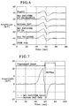
- Figure 6 shows a set of related curves for use in comparing the detection point with and without a median filter 6 plus the post filter 7 for a "clean" intrinsic deflection signal SI, without any external disturbance.
- the signal Postfilt is the input signal to the detector 8, i.e., the "smooth" output from the post filter 7.
- the signal designated Intr Defl + GSM, LP Filt + Medfilt(5) is the output signal from the median filter 6 (i.e., just before the post filter 7, the designation (5) indicating that a five-point median filter has been used.
- the signal Intrinsic Defl is the "clean" unipolar intrinsic deflection signal SI, with no disturbance added thereon.
- the signal designated GSM Only represents the disturbance signal (in the discussion below), but in this case since there is no disturbance this signal has a constant zero value.
- Figure 7 shows the unprocessed detection signal Unprocessed Detect, for the case shown in Figure 6. Since the disturbance is zero, the signal Intr Defl + GSM and the signal Intrinsic Defl Only coincide.
- Unprocessed in the context of Figure 7 means that no median filtering and no post filtering were undertaken. This case can be considered as if the input of the detector 8 were directly connected to the output of the converter 5. This is for the purpose of identifying an "ideal" detection point for use as a benchmark in subsequent comparisons. As shown in Figure 7, the ideal detection point in this case is at 60.55 ms.
- Figure 8 shows the processed detect signal Processed Detect, which represents the detection time when median filtering and post filtering are used, i.e., all components are connected as shown in Figure 1.
- the input signal is the "clean" intrinsic deflection signal SI shown in Figure 6.
- the detection point is now at 61.52 ms. This represents a short delay of approximately 1 ms from the ideal case represented in Figure 7.
- the designation (5) indicates that a five-point median filter was used.
- Figure 9 shows the same set of curves as was described in connection with Figure 6, this time in the presence of a GSM disturbance SG, which produces the signal designated GSM Only shown in Figure 9.
- This disturbance is shown superimposed on the intrinsic deflection signal in the signal designated Intr Defl + GSM in Figure 9.
- a "zoom" of this signal is shown in Figure 10.
- the effect of median filtering and post filtering in accordance with the invention on the cardiac event detection is shown in Figure 11, wherein it can be seen that the detection point is unchanged compared to the detection point associated with the undisturbed signal.
- median filtering in general, is a technique which has previously been employed in signal processing, although not for the specific purpose nor to achieve the specific results described herein.
- the following discussion presents known examples of median filter hardware, which can be used to accomplish the median filtering, employed herein.
- a median filter is basically a sorting network, with sorting successively taking place at a number of nodes.
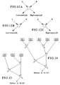
- Symbolic notations for the three basic types of nodes employed in a median filter are respectively shown in Figures 12A, 12B and 12C.
- Each node has two inputs, respectively designated in the symbolic notation as A and B.
- the node shown in Figure 12A produces two outputs, one of which is designated as the low output, and constitutes the minimum of A and B.
- the other output is the high output, which constitutes the maximum of A and B.
- the node symbolically represented in Figure 12B produces only a low output
- the node symbolically represented in Figure 12C produces only a high output.
- Figure 13 shows the basic structure, using the symbolism from Figures 12A, 12B and 12C, for a network (median filter) which produces a median from a three-point input, the inputs respectively being X1, X2 and X3. The resulting output is the median of the three input values.
- Figure 14 shows the basic structure of a network (median filter) for producing the median from a five-point input, the inputs being X1, X2, X3, X4 and X5. Higher order filters (networks) can be devised along the same principle.
- Figure 15A shows a block diagram of a data selector/multiplexer 11 which can be used in an exemplary embodiment of a hardware realization of a sorting node in the median filter 6 employed in the invention.
- Figure 16A shows a block diagram of a data magnitude comparator 12 usable in combination with the data selector/multiplexer 11 shown in Figure 15A to build a sorting node.
- the depiction of these components as having parallel 8-bit input buses assumes that the resolution of the analog-to-digital converter 5 is 8-bits, and that the output of the converter 5 is supplied on a 8-bit bus as well.
- Figure 15B shows the logical function table for the data selector/multiplexer 11 of Figure 15A
- Figure 16B shows the logical function table for the magnitude comparator 12 of Figure 16A.
- FIG. 17A An exemplary combination of these components to form a two element sorting node is shown in Figure 17A, with the logical function table therefor being shown in Figure 17B.
- the hardware embodiment shown in Figure 17A is for a sorting node as symbolically represented in Figure 12A, having both a low output (designated U in Figure 17A) and a high output (designated V in Figure 17A).
- the multiplexer M2 For constructing a sorting node as symbolically represented in Figure 12B, having a minimum output only, the multiplexer M2 is omitted from the circuitry shown in Figure 17A.
- the multiplexer M1 For constructing a sorting node as symbolically represented in Figure 12C, having maximum output only, the multiplexer M1 is omitted from the circuitry of Figure 17A.
- Figure 18 is a block diagram of a hardware realization of a three-point median filter as an exemplary embodiment of the median filter 6 of Figure 1.
- the respective inputs X1, X2 and X3 are produced by shift registers 13, 14 and 15. These inputs are supplied to a three-point sorting network 16 as described in connection with Figure 13.
- Each sorting node of the three-point sorting network 16 may be constructed as shown in Figure 17A.
- the analog-to-digital converter 5 and the shift registers 13, 14 and 15 are shown in Figure 18 as being operated by clock signals from control logic 17.
- the control logic 17 need not be a separate component, but can be embodied in the overall pacing control logic 9, in the form of a suitably programmed microprocessor.
- a median filter in addition to allowing accurate detection to proceed even in the presence of noise such as GSM disturbance, also provides a means for making a simple detection as to whether an incoming signal is simply too noisy to be permitted to be detected.
- the processed signal i.e., the signal after median filtering and post filtering, to the unprocessed signal, it is possible to define a " severe noise threshold” or "noise capture level” before the processed signal is supplied to the detector 8. If this threshold is exceeded, the signal is simply rejected outright, since it is assumed that the noise content of the signal is so high that, even though processed in accordance with the invention, making a detection based on that signal would be unacceptable suspect.
Landscapes
- Health & Medical Sciences (AREA)
- Cardiology (AREA)
- Heart & Thoracic Surgery (AREA)
- Engineering & Computer Science (AREA)
- Biomedical Technology (AREA)
- Nuclear Medicine, Radiotherapy & Molecular Imaging (AREA)
- Radiology & Medical Imaging (AREA)
- Life Sciences & Earth Sciences (AREA)
- Animal Behavior & Ethology (AREA)
- General Health & Medical Sciences (AREA)
- Public Health (AREA)
- Veterinary Medicine (AREA)
- Measurement And Recording Of Electrical Phenomena And Electrical Characteristics Of The Living Body (AREA)
- Electrotherapy Devices (AREA)
Applications Claiming Priority (2)
| Application Number | Priority Date | Filing Date | Title |
|---|---|---|---|
| US53691 | 1998-04-02 | ||
| US09/053,691 US5871509A (en) | 1998-04-02 | 1998-04-02 | Method and apparatus to remove data outliers, produced by external disturbance, in internally measured signals in an implantable cardiac stimulator |
Publications (3)
| Publication Number | Publication Date |
|---|---|
| EP0947217A2 true EP0947217A2 (fr) | 1999-10-06 |
| EP0947217A3 EP0947217A3 (fr) | 2000-12-20 |
| EP0947217B1 EP0947217B1 (fr) | 2005-06-01 |
Family
ID=21985909
Family Applications (1)
| Application Number | Title | Priority Date | Filing Date |
|---|---|---|---|
| EP98121828A Expired - Lifetime EP0947217B1 (fr) | 1998-04-02 | 1998-11-17 | Appareil pour la suppression de déviations produites par des perturbations externes dans des signaux internes, mesurés dans un stimulateur cardiaque implantable |
Country Status (3)
| Country | Link |
|---|---|
| US (1) | US5871509A (fr) |
| EP (1) | EP0947217B1 (fr) |
| DE (1) | DE69830385T2 (fr) |
Families Citing this family (49)
| Publication number | Priority date | Publication date | Assignee | Title |
|---|---|---|---|---|
| US5978710A (en) | 1998-01-23 | 1999-11-02 | Sulzer Intermedics Inc. | Implantable cardiac stimulator with safe noise mode |
| DE19927616A1 (de) * | 1999-06-17 | 2000-12-21 | Biotronik Mess & Therapieg | Verfahren und Vorrichtung zur Unterscheidung zwischen elektromagnetischen Störsignalen und elektromedizinischen Abtastsignalen insbesondere von kardiologischen Implantaten |
| US6246907B1 (en) * | 1999-12-01 | 2001-06-12 | Cardiacscience, Inc. | Automatic external cardioverter/defibrillator with cardiac rate detector and method of operating the same |
| US6526359B1 (en) * | 1999-12-10 | 2003-02-25 | Growth Financial Ag | Apparatus and method for measuring small increases in machine tool drive motor power |
| US6925328B2 (en) | 2000-04-20 | 2005-08-02 | Biophan Technologies, Inc. | MRI-compatible implantable device |
| US8527046B2 (en) | 2000-04-20 | 2013-09-03 | Medtronic, Inc. | MRI-compatible implantable device |
| SE0004224D0 (sv) | 2000-11-16 | 2000-11-16 | St Jude Medical | Medical device |
| US20020116029A1 (en) | 2001-02-20 | 2002-08-22 | Victor Miller | MRI-compatible pacemaker with power carrying photonic catheter and isolated pulse generating electronics providing VOO functionality |
| US6829509B1 (en) | 2001-02-20 | 2004-12-07 | Biophan Technologies, Inc. | Electromagnetic interference immune tissue invasive system |
| US6731979B2 (en) | 2001-08-30 | 2004-05-04 | Biophan Technologies Inc. | Pulse width cardiac pacing apparatus |
| US7054686B2 (en) * | 2001-08-30 | 2006-05-30 | Biophan Technologies, Inc. | Pulsewidth electrical stimulation |
| US7215993B2 (en) * | 2002-08-06 | 2007-05-08 | Cardiac Pacemakers, Inc. | Cardiac rhythm management systems and methods for detecting or validating cardiac beats in the presence of noise |
| US6917830B2 (en) * | 2001-10-29 | 2005-07-12 | Cardiac Pacemakers, Inc. | Method and system for noise measurement in an implantable cardiac device |
| US6892092B2 (en) * | 2001-10-29 | 2005-05-10 | Cardiac Pacemakers, Inc. | Cardiac rhythm management system with noise detector utilizing a hysteresis providing threshold |
| WO2003037399A2 (fr) * | 2001-10-31 | 2003-05-08 | Biophan Technologies, Inc. | Logement de composant hermetique pour catheter photonique |
| US6968236B2 (en) | 2002-01-28 | 2005-11-22 | Biophan Technologies, Inc. | Ceramic cardiac electrodes |
| US6711440B2 (en) | 2002-04-11 | 2004-03-23 | Biophan Technologies, Inc. | MRI-compatible medical device with passive generation of optical sensing signals |
| US6941332B2 (en) * | 2002-04-23 | 2005-09-06 | Medtronic, Inc. | Implantable medical device fast median filter |
| US6898461B2 (en) * | 2002-04-23 | 2005-05-24 | Medtronic, Inc. | Implantable medical device stream processor |
| US6725092B2 (en) | 2002-04-25 | 2004-04-20 | Biophan Technologies, Inc. | Electromagnetic radiation immune medical assist device adapter |
| US6925322B2 (en) * | 2002-07-25 | 2005-08-02 | Biophan Technologies, Inc. | Optical MRI catheter system |
| DE10245555A1 (de) * | 2002-09-30 | 2004-04-15 | Siemens Audiologische Technik Gmbh | Drahtloses Übertragungssystem für Hörgeräte |
| US7908006B2 (en) * | 2004-12-15 | 2011-03-15 | Cardiac Pacemakers, Inc. | Cardiac pacing response classification using an adaptable classification interval |
| US7734347B2 (en) * | 2004-12-15 | 2010-06-08 | Cardiac Pacemakers, Inc. | Cardiac pacing response classification based on waveform feature variability |
| US7587240B2 (en) * | 2004-12-15 | 2009-09-08 | Cardiac Pacemakers, Inc. | Atrial capture verification |
| US7330761B2 (en) * | 2004-12-15 | 2008-02-12 | Cardiac Pacemakers, Inc. | Baseline adaptation for cardiac pacing response classification |
| US8229561B2 (en) | 2004-12-15 | 2012-07-24 | Cardiac Pacemakers, Inc. | Atrial retrograde management |
| US7930029B2 (en) * | 2004-12-15 | 2011-04-19 | Cardiac Pacemakers, Inc. | Template initialization for evoked response detection |
| US7561915B1 (en) | 2004-12-17 | 2009-07-14 | Cardiac Pacemakers, Inc. | MRI system having implantable device safety features |
| US8014867B2 (en) | 2004-12-17 | 2011-09-06 | Cardiac Pacemakers, Inc. | MRI operation modes for implantable medical devices |
| TWI258123B (en) * | 2005-02-03 | 2006-07-11 | Lite On It Corp | Apparatus for positioning a clamper of a disc driver |
| US7444180B2 (en) * | 2005-05-25 | 2008-10-28 | Boston Scientific Neuromodulation Corporation | Implantable microstimulator with dissecting tip and/or retrieving anchor and methods of manufacture and use |
| US7457666B2 (en) | 2005-05-25 | 2008-11-25 | Cardiac Pacemakers, Inc. | Retrograde atrial sensing for identifying sub-threshold atrial pacing |
| GB2431470A (en) * | 2005-10-21 | 2007-04-25 | Autoliv Dev | Assessing blood concentration of a volatile constituent |
| US7801610B2 (en) * | 2006-11-17 | 2010-09-21 | Cardiac Pacemakers, Inc. | Methods and systems for management of atrial retrograde conduction and pacemaker mediated tachyarrhythmia |
| US8290590B2 (en) * | 2006-11-17 | 2012-10-16 | Cardiac Pacemakers, Inc. | Dynamic morphology based atrial automatic threshold |
| US8032228B2 (en) | 2007-12-06 | 2011-10-04 | Cardiac Pacemakers, Inc. | Method and apparatus for disconnecting the tip electrode during MRI |
| US8086321B2 (en) | 2007-12-06 | 2011-12-27 | Cardiac Pacemakers, Inc. | Selectively connecting the tip electrode during therapy for MRI shielding |
| US9839395B2 (en) | 2007-12-17 | 2017-12-12 | Dexcom, Inc. | Systems and methods for processing sensor data |
| US8311637B2 (en) | 2008-02-11 | 2012-11-13 | Cardiac Pacemakers, Inc. | Magnetic core flux canceling of ferrites in MRI |
| US8160717B2 (en) | 2008-02-19 | 2012-04-17 | Cardiac Pacemakers, Inc. | Model reference identification and cancellation of magnetically-induced voltages in a gradient magnetic field |
| US8571661B2 (en) * | 2008-10-02 | 2013-10-29 | Cardiac Pacemakers, Inc. | Implantable medical device responsive to MRI induced capture threshold changes |
| EP2398553B1 (fr) | 2009-02-19 | 2015-07-22 | Cardiac Pacemakers, Inc. | Systèmes de thérapie de l'arythmie en environnements irm |
| US8452405B2 (en) | 2009-05-05 | 2013-05-28 | Cardiac Pacemakers, Inc. | Methods and systems for mitigating the occurrence of arrhythmia during atrial pacing |
| WO2011063858A1 (fr) | 2009-11-30 | 2011-06-03 | St. Jude Medical Ab | Procédé et dispositif de détection de bruit |
| EP2509682B1 (fr) * | 2009-12-08 | 2015-01-14 | Cardiac Pacemakers, Inc. | Dispositif médical implantable pour détection et commande automatiques de tachycardie dans environnements d'imagerie par résonance magnétique |
| US20110300874A1 (en) * | 2010-06-04 | 2011-12-08 | Apple Inc. | System and method for removing tdma audio noise |
| US9126055B2 (en) | 2012-04-20 | 2015-09-08 | Cardiac Science Corporation | AED faster time to shock method and device |
| GB2532480B (en) | 2014-11-20 | 2019-06-05 | Veoneer Sweden Ab | A breath analyser device |
Citations (5)
| Publication number | Priority date | Publication date | Assignee | Title |
|---|---|---|---|---|
| US5114568A (en) | 1990-07-13 | 1992-05-19 | Earth Solutions, Inc. | Reclamation system for contaminated material |
| US5138567A (en) | 1990-03-23 | 1992-08-11 | Deutsche Itt Industries Gmbh | Median filter |
| US5343870A (en) | 1991-11-12 | 1994-09-06 | Quinton Instrument Company | Recorder unit for ambulatory ECG monitoring system |
| EP0713714A2 (fr) | 1994-11-22 | 1996-05-29 | Ventritex, Inc. | Système de commande, pour appareils médicaux, sensible aux interférences électromagnétiques, basé sur un correlateur |
| US5527344A (en) | 1994-08-01 | 1996-06-18 | Illinois Institute Of Technology | Pharmacologic atrial defibrillator and method |
Family Cites Families (2)
| Publication number | Priority date | Publication date | Assignee | Title |
|---|---|---|---|---|
| US5144568A (en) * | 1987-05-26 | 1992-09-01 | Sundstrand Corporation | Fast median filter |
| US5630425A (en) * | 1995-02-17 | 1997-05-20 | Ep Technologies, Inc. | Systems and methods for adaptive filtering artifacts from composite signals |
-
1998
- 1998-04-02 US US09/053,691 patent/US5871509A/en not_active Expired - Lifetime
- 1998-11-17 EP EP98121828A patent/EP0947217B1/fr not_active Expired - Lifetime
- 1998-11-17 DE DE69830385T patent/DE69830385T2/de not_active Expired - Lifetime
Patent Citations (5)
| Publication number | Priority date | Publication date | Assignee | Title |
|---|---|---|---|---|
| US5138567A (en) | 1990-03-23 | 1992-08-11 | Deutsche Itt Industries Gmbh | Median filter |
| US5114568A (en) | 1990-07-13 | 1992-05-19 | Earth Solutions, Inc. | Reclamation system for contaminated material |
| US5343870A (en) | 1991-11-12 | 1994-09-06 | Quinton Instrument Company | Recorder unit for ambulatory ECG monitoring system |
| US5527344A (en) | 1994-08-01 | 1996-06-18 | Illinois Institute Of Technology | Pharmacologic atrial defibrillator and method |
| EP0713714A2 (fr) | 1994-11-22 | 1996-05-29 | Ventritex, Inc. | Système de commande, pour appareils médicaux, sensible aux interférences électromagnétiques, basé sur un correlateur |
Also Published As
| Publication number | Publication date |
|---|---|
| EP0947217A3 (fr) | 2000-12-20 |
| US5871509A (en) | 1999-02-16 |
| DE69830385T2 (de) | 2006-02-02 |
| DE69830385D1 (de) | 2005-07-07 |
| EP0947217B1 (fr) | 2005-06-01 |
Similar Documents
| Publication | Publication Date | Title |
|---|---|---|
| EP0947217B1 (fr) | Appareil pour la suppression de déviations produites par des perturbations externes dans des signaux internes, mesurés dans un stimulateur cardiaque implantable | |
| US8868170B2 (en) | Active medical device, including an implantable defibrillator, for detection of QRS complexes in a very noisy signal | |
| US5571144A (en) | Method of verifying capture of the atrium by a cardiac stimulator | |
| US5431693A (en) | Method of verifying capture of the heart by a pacemaker | |
| EP0717646B1 (fr) | Appareil et procede de detection de capture dans un stimulateur cardiaque | |
| EP3448512B1 (fr) | Système de détection dans un défibrillateur cardioverteur implantable extra-cardiovasculaire | |
| US7715906B2 (en) | Method and apparatus for detecting noise in an implantable medical device | |
| US6641541B1 (en) | Method and apparatus for a morphology-preserving smoothing filter | |
| US6119043A (en) | Atrial and ventricular cardiac lead having a mechanical bias | |
| EP0826392B1 (fr) | Appareil d'extraction d'une composante de réponse provoquée à partir d'un signal cardiaque mesuré, en supprimant les composantes de polarisation d'électrode | |
| EP4591794A2 (fr) | Morphologie de signal électrique cardiaque et rejet de surdétection d'onde t sur la base d'un motif | |
| US5702425A (en) | Apparatus and method of noise classification in an implantable cardiac device | |
| US20060235476A1 (en) | Method and apparatus for identifying oversensing using far-field intracardiac electrograms and marker channels | |
| US6016446A (en) | Cardiac rhythm management system including nonlinear, non-blanking sense amplifier | |
| CN109561844A (zh) | 用于抑制室性快速性心律失常检测的基于心脏电信号总体形态的噪声检测 | |
| DE3535504A1 (de) | Herzschrittmacher | |
| EP0321764A1 (fr) | Méthode et moyens pour détecter un évènement dans un signal | |
| EP0249819B2 (fr) | Stimulateur cardiaque pour entraíner le coeur humain | |
| EP0249824B1 (fr) | Stimulateur cardiaque pour entraîner le coeur humain | |
| US7693574B2 (en) | System and method for discriminating high frequency electromagnetic interference from cardiac events | |
| JP2002315050A (ja) | 移動体通信機器及び障害電波制御システム |
Legal Events
| Date | Code | Title | Description |
|---|---|---|---|
| PUAI | Public reference made under article 153(3) epc to a published international application that has entered the european phase |
Free format text: ORIGINAL CODE: 0009012 |
|
| AK | Designated contracting states |
Kind code of ref document: A2 Designated state(s): DE FR IT NL |
|
| AX | Request for extension of the european patent |
Free format text: AL;LT;LV;MK;RO;SI |
|
| PUAL | Search report despatched |
Free format text: ORIGINAL CODE: 0009013 |
|
| AK | Designated contracting states |
Kind code of ref document: A3 Designated state(s): AT BE CH CY DE DK ES FI FR GB GR IE IT LI LU MC NL PT SE |
|
| AX | Request for extension of the european patent |
Free format text: AL;LT;LV;MK;RO;SI |
|
| RAP1 | Party data changed (applicant data changed or rights of an application transferred) |
Owner name: ST. JUDE MEDICAL AB |
|
| 17P | Request for examination filed |
Effective date: 20010620 |
|
| AKX | Designation fees paid |
Free format text: DE FR IT NL |
|
| GRAP | Despatch of communication of intention to grant a patent |
Free format text: ORIGINAL CODE: EPIDOSNIGR1 |
|
| GRAS | Grant fee paid |
Free format text: ORIGINAL CODE: EPIDOSNIGR3 |
|
| GRAA | (expected) grant |
Free format text: ORIGINAL CODE: 0009210 |
|
| AK | Designated contracting states |
Kind code of ref document: B1 Designated state(s): DE FR IT NL |
|
| PG25 | Lapsed in a contracting state [announced via postgrant information from national office to epo] |
Ref country code: NL Free format text: LAPSE BECAUSE OF FAILURE TO SUBMIT A TRANSLATION OF THE DESCRIPTION OR TO PAY THE FEE WITHIN THE PRESCRIBED TIME-LIMIT Effective date: 20050601 |
|
| REF | Corresponds to: |
Ref document number: 69830385 Country of ref document: DE Date of ref document: 20050707 Kind code of ref document: P |
|
| NLV1 | Nl: lapsed or annulled due to failure to fulfill the requirements of art. 29p and 29m of the patents act | ||
| PLBE | No opposition filed within time limit |
Free format text: ORIGINAL CODE: 0009261 |
|
| STAA | Information on the status of an ep patent application or granted ep patent |
Free format text: STATUS: NO OPPOSITION FILED WITHIN TIME LIMIT |
|
| ET | Fr: translation filed | ||
| 26N | No opposition filed |
Effective date: 20060302 |
|
| PGFP | Annual fee paid to national office [announced via postgrant information from national office to epo] |
Ref country code: DE Payment date: 20091125 Year of fee payment: 12 |
|
| PGFP | Annual fee paid to national office [announced via postgrant information from national office to epo] |
Ref country code: IT Payment date: 20091124 Year of fee payment: 12 Ref country code: FR Payment date: 20091214 Year of fee payment: 12 |
|
| REG | Reference to a national code |
Ref country code: DE Ref legal event code: R119 Ref document number: 69830385 Country of ref document: DE Effective date: 20110601 Ref country code: DE Ref legal event code: R119 Ref document number: 69830385 Country of ref document: DE Effective date: 20110531 |
|
| REG | Reference to a national code |
Ref country code: FR Ref legal event code: ST Effective date: 20110801 |
|
| PG25 | Lapsed in a contracting state [announced via postgrant information from national office to epo] |
Ref country code: DE Free format text: LAPSE BECAUSE OF NON-PAYMENT OF DUE FEES Effective date: 20110531 |
|
| PG25 | Lapsed in a contracting state [announced via postgrant information from national office to epo] |
Ref country code: FR Free format text: LAPSE BECAUSE OF NON-PAYMENT OF DUE FEES Effective date: 20101130 |
|
| PG25 | Lapsed in a contracting state [announced via postgrant information from national office to epo] |
Ref country code: IT Free format text: LAPSE BECAUSE OF NON-PAYMENT OF DUE FEES Effective date: 20101117 |