EP0949743A2 - Electrical machine, in particular for lift driving apparatus - Google Patents
Electrical machine, in particular for lift driving apparatus Download PDFInfo
- Publication number
- EP0949743A2 EP0949743A2 EP99106572A EP99106572A EP0949743A2 EP 0949743 A2 EP0949743 A2 EP 0949743A2 EP 99106572 A EP99106572 A EP 99106572A EP 99106572 A EP99106572 A EP 99106572A EP 0949743 A2 EP0949743 A2 EP 0949743A2
- Authority
- EP
- European Patent Office
- Prior art keywords
- stator
- electrical machine
- external rotor
- machine according
- braking device
- Prior art date
- Legal status (The legal status is an assumption and is not a legal conclusion. Google has not performed a legal analysis and makes no representation as to the accuracy of the status listed.)
- Withdrawn
Links
- 239000002904 solvent Substances 0.000 claims description 9
- 238000004804 winding Methods 0.000 claims description 9
- 230000005540 biological transmission Effects 0.000 claims description 6
- 238000003825 pressing Methods 0.000 claims description 4
- 238000012546 transfer Methods 0.000 claims description 3
- 230000005674 electromagnetic induction Effects 0.000 claims description 2
- 238000010276 construction Methods 0.000 abstract 1
- 238000011109 contamination Methods 0.000 abstract 1
- 238000013461 design Methods 0.000 description 4
- 238000003860 storage Methods 0.000 description 4
- 238000001816 cooling Methods 0.000 description 3
- 230000001960 triggered effect Effects 0.000 description 2
- 238000005299 abrasion Methods 0.000 description 1
- 238000006073 displacement reaction Methods 0.000 description 1
- 238000009826 distribution Methods 0.000 description 1
- 230000000694 effects Effects 0.000 description 1
- 230000017525 heat dissipation Effects 0.000 description 1
- 238000007373 indentation Methods 0.000 description 1
- 238000012423 maintenance Methods 0.000 description 1
- 238000004519 manufacturing process Methods 0.000 description 1
- 239000000463 material Substances 0.000 description 1
- 238000000034 method Methods 0.000 description 1
- 229910001172 neodymium magnet Inorganic materials 0.000 description 1
- 238000013021 overheating Methods 0.000 description 1
- 239000002245 particle Substances 0.000 description 1
- 230000001681 protective effect Effects 0.000 description 1
- 238000005096 rolling process Methods 0.000 description 1
- 238000000926 separation method Methods 0.000 description 1
- 239000007858 starting material Substances 0.000 description 1
- 238000012549 training Methods 0.000 description 1
Images

Classifications
-
- H—ELECTRICITY
- H02—GENERATION; CONVERSION OR DISTRIBUTION OF ELECTRIC POWER
- H02K—DYNAMO-ELECTRIC MACHINES
- H02K7/00—Arrangements for handling mechanical energy structurally associated with dynamo-electric machines, e.g. structural association with mechanical driving motors or auxiliary dynamo-electric machines
- H02K7/10—Structural association with clutches, brakes, gears, pulleys or mechanical starters
- H02K7/102—Structural association with clutches, brakes, gears, pulleys or mechanical starters with friction brakes
- H02K7/1021—Magnetically influenced friction brakes
- H02K7/1023—Magnetically influenced friction brakes using electromagnets
- H02K7/1025—Magnetically influenced friction brakes using electromagnets using axial electromagnets with generally annular air gap
-
- H—ELECTRICITY
- H02—GENERATION; CONVERSION OR DISTRIBUTION OF ELECTRIC POWER
- H02K—DYNAMO-ELECTRIC MACHINES
- H02K7/00—Arrangements for handling mechanical energy structurally associated with dynamo-electric machines, e.g. structural association with mechanical driving motors or auxiliary dynamo-electric machines
- H02K7/10—Structural association with clutches, brakes, gears, pulleys or mechanical starters
Definitions
- the invention relates to an electrical machine, in particular for an elevator drive, with a fixed one internal stator and one essentially the machine housing forming rotating external rotor, at least partially overlaps the stator and in the outer area of it axial expansion is supported, stator and external rotor via a radial separating, but in the axial direction running air gap in electromagnetically induced Connected to each other (radial field motor).
- EP 631 967 describes a traction sheave elevator which has a very flat engine.
- the Stator the machine housing with a radially inner one Stator coil, the elevator cables on the circumference of the rotor are stored.
- the runner has only one side Stock on.
- a flat drive engine designed as a disc motor, in which the elevator ropes on one inside the rotor spool on the suspended inside the engine part attached drive pulley are.
- the object of the invention is an electrical machine especially for an elevator drive, to create the Avoids problems of the prior art, especially one increased operational safety and reduced maintenance requirements guaranteed in a compact design and is versatile.
- the rotating one external runner has the advantage that it for improved cooling swirls cooling air itself.
- One in the machine housing arranged braking device is both protected against damage as well as pollution.
- Prefers the braking device is outside of an engine part that in particular the cylindrical one surrounded by the air gap May include space. Due to the spatial separation of the braking device from the engine part there is greater scope created for the braking device and their Accessibility improved. In addition, the engine part better against abrasion particles of the braking device or the like. to be protected.
- the braking device is particularly preferred in the area of a or radially within a coupled with the external rotor Driving wheel arranged to drive the rope, the braking device directly or indirectly partially with the driving wheel can be connected.
- the brake can be directly on the driving wheel be supported and forces generated when braking between the moving elevator car and the fixed mounting of the Machine transferred.
- the braking device can have braking surfaces, each are assigned to the stator and the external rotor, preferably each in at least four levels for the stator and external rotor.
- the braking surfaces can advantageously at least partially be movable or movable, in particular by Brake pressure or a pressing force in the axial direction of the Machine can be pressed against each other.
- the Braking surfaces can be moved over a certain range, especially in the axial direction. At least they can partially supported or stored freely movable and in separated state a certain distance from each have corresponding surface.
- the braking surfaces of the stator and / or the are preferred Outer rotor essentially running in the circumferential direction formed with circular ring surfaces, the circular rings in particular be divided into several circular ring sectors can. These can each be approximately the same size and at a particularly preferred embodiment of the invention independently from each other in the area of the same braking surface be movable. This enables a division, for example the braking device in two or more parts, individually or can be operated in groups.
- the braking surfaces on annular disks can be particularly preferred be arranged, preferably two braking surfaces a circular washer on the front and back can be trained.
- a preferred embodiment can provide that several circular washers Stator and external rotor alternately interlocking as Disc brakes are formed, preferably at least an annular disc is axially firmly supported.
- a support on the stator is preferred, this Fixed circular ring disc at one end of the multi-disc brake can be arranged and only on the to Provide the multi-disc brake side with a braking surface is. This means that the multi-disc brake is only required from one side pressure to be exerted.
- An actuator for the braking device is preferably arranged on the stator, it preferably a closing device for closing the braking device, especially by exerting the pressure, and at least one Have release device for releasing the braking device can.
- These devices preferably each comprise closing elements and / or release elements.
- the Closing device at least one elastic mechanical Locking element for applying the pressure force. Whose Direction of action advantageously runs axially and in particular through the braking surfaces to the contact pressure as possible bring evenly distributed on the braking surfaces.
- a design of the closing elements is particularly advantageous viewed as a coil spring or coil spring.
- the Safety function of the braking device can be improved when the locking device or the locking elements exert a permanent pressure force on the braking device, so that, for example, springs are permanently biased System against the braking surfaces.
- For better Distribution of the pressure force can be in several closing elements Provided evenly distributed circumferential direction, and their directions of action, in particular through the external Area of the braking surfaces of the stator. With divided Braking surfaces is preferably one closing element per segment available.
- the release device can have at least one release element, preferably an electromechanical release element, the can be designed as an electromagnet.
- a preferred one Training looks essentially circumferential wound and / or extending in the axial direction before, preferably at least a short distance from each other a locking element of the locking device can. It can be either a rotating coil or two separate, parallel rotating coils are available be.
- At least one release element preferably surrounds at least a closing element, in a particularly preferred embodiment all locking elements are surrounded by release elements. This enables a more direct transfer of the release force from the release elements on the closing elements, preferably over a pressure surface, so that in the normal operating state Machine as a result of a lack of pressure force the braking surfaces are spaced from each other and no braking torque apply.
- additional Solvents for releasing the braking device may be provided, which are preferably designed as mechanical solvents and in particular have a power transmission element can transmit forces in at least one longitudinal direction can.
- additional ones are particularly preferred Solvent in an electromechanical release device because for example, the electrically operated in the event of a power failure Release device fails, the braking device is activated and the brake closes.
- to release the brake can be mechanical, for example manually operated, Solvents particularly advantageous.
- the power transmission element can be designed as a Bowden cable, which by a Axial bore in the inner stator shaft from the Machine can be led out for external actuation.
- a deflection device can be provided, preferably at least one deflection roller or a deflection lever. These can allow the outside of the Brake device attacking power transmission element in the lead the central area of the machine out of it.
- At least part of the generation of electromagnetic Induction in the air gap can be done through an electrical coil take place, which is arranged in particular on the stator, preferably as a stator winding, the longitudinal axis of this Coil runs in the axial direction of the machine.
- a preferred one Number of poles is 24 or more.
- a power supply the stator coil or stator winding can pass through the stator run, in particular through a stator shaft, in the preferably a channel for cables and possibly others Supply lines is formed, which in this way from the Machine are brought out.
- the machine can with at least be provided with a permanent magnet, for example made of NdFeB material, whereby it preferably has a low radial Has thickness.
- a permanent magnet for example made of NdFeB material, whereby it preferably has a low radial Has thickness.
- Mass can be at least one permanent magnet on the Outrunner be arranged. In this way, the crowd the outer rotor, which has a larger radius than that internal stator can be kept low. For manufacturing reasons it is preferably divided into smaller sections, which are distributed in a subsequent arrangement.
- the Driving wheel as rope drum with several external and in Circumferential grooves for receiving such as Drive the rope or an elevator attached to it be formed by friction.
- the cable drum is attached directly to the electrical machine, especially on the external rotor without a gear or the like To be free in the dimensioning of the diameter it can be axially offset from the motor part or from the space surrounding the air gap. Especially it may have a smaller diameter than the air gap have, which results in a higher engine speed realize at a certain elevator speed leaves.
- the cable drum can be on a section of the external rotor or its housing can be placed, preferably on one end of the outrunner.
- the cable drum from the outer rotor be formed, in particular from a part its outer surface, either from the engine part or preferably from one end of the outrunner.
- the external rotor is particularly preferred the area surrounded by the cable drum, in particular outside the engine part.
- Such a direct one Support of the rope drum on the bearing and thus the Stator is particularly good at those caused by the rope Take up forces in the radial direction so that it is neither too denting the rope drum to decenter it the machine can come.
- the external rotor is particularly preferred stored in the area of its two ends, in particular with rolling bearings, with an attachment of the bearings to the two Ends of the stator is particularly preferred.
- a circumferential circumferential Teeth On the external rotor, especially on the drive wheel adjacent area, a circumferential circumferential Teeth, preferably a ring gear, may be provided.
- the Teeth themselves can run axially or slightly obliquely axially.
- the ring gear can be formed on the outer rotor or as separate component can be attached.
- To the gearing is preferably via an axially movable gear or pinion
- Emergency drive motor can be coupled, for example via a Magnet drive, similar to a starter pinion for one Car engine.
- the emergency drive motor which is preferably used as a DC motor is carried out, for example, for a so-called emergency or evacuation drive its driving force on the external rotor or drives the machine.
- the emergency drive motor can be via a battery or an accumulator be fed, whereby its performance, possibly in the event of overload, only be designed for short operation can.
- Another field of application of the invention can be found in Field of printing presses, especially as a drive for pressure waves.
- FIG. 1 shows an electrical machine according to the invention 11, which consists of a fixed stator 12 and one around the Stator rotating outer rotor 13 is made. 1 is the stator 12 at its two outer ends on two bearing blocks 14 held, by means of which it is mounted on a carrier or a carrier plate can be attached, preferably by Screw connection. Of course they all offer themselves Storage options, deviating from that shown in Fig. 1 shown.
- the outer rotor is 13 rotatably supported on the stator 12.
- the right warehouse 16 extends from a front housing shell 17 first radially outwards, then with an approximately rectangular one Bend the length of the outer rotor a little in Direction to the right bearing block 14 so far until it almost reaches it and from then on with you Another kink in the radial direction up to the outer diameter extends.
- the front housing shell 17 with a rear housing shell 18 through the front Housing screws 19 connected.
- the rear case shell 18 extends across the stator 12 in the axial direction over about two thirds of the length of the external rotor 13, and then to pass into a diameter constriction 20. From the left end the diameter constriction 20 runs the housing shell radially inwards and opens into a receptacle 21 for the left bearing 16.
- Rope drum 23 By means of a radially inward reaching paragraph 24 it lies in a circumferential corner groove the diameter constriction 20, with the end face bores for receiving cable drum screws 25, which are in axial Engage in the rear housing shell 18 in the direction having.
- Rope drum 23 and rear housing shell 18 the outer rotor 13 approximately flush from.
- the cable drum 23 has several provided in the circumferential direction grooves 27 which for Inclusion of a rope are provided on which an elevator car is attached.
- stator 12 has its ends are held in the bearing blocks 14, in the middle area a radially projecting carrier 29 on its External cross section carries the stator winding 30.
- the stator winding 30 is arranged in a laminated core 31, which by means of a continuous screw 32 with a radial protruding fastening projection 33 of the carrier 29 screwed is.
- the screw 32 not only provides the Cohesion of the laminated core 31 safely, but ensures about it for torque transmission as well as an exact Positioning the stator winding.
- Several coils of the winding, depending on the number of poles, are in the circumferential direction distributed.
- the stator winding 30 takes the whole Longitudinal area of the outer rotor 13 in the wide Diameter and has only a small amount in the axial direction Distance to the inside of the front housing shell 17 and the rear diameter constriction 20.
- the carrier 29 connects to the left to the stator 12 the braking device 40, the actuating device 42 extends to the carrier 29.
- the actuating device 42 extends to the carrier 29.
- FIG. 2 shows a view of the machine according to the invention 11 from the front of the rear housing shell 18. It is clearly seen, like the left end of the shaft 28 in FIG. 1 of the stator with a somewhat flattened cross section in one corresponding receiving recess 45, which is a central has vertical slot 46 is added. Above A fastening screw 47 runs through the receiving recess through the two sections of the Bearing blocks 14 to press them against each other and thus to hold the shaft end securely in the receiving recess 45.
- the brake points a brake caliper 50, which both the braking device 40 as well as the actuator 42 carries.
- On the brake caliper 50 are six stator brake disks 51 in the form of Annular discs arranged in the radially inner part or recesses of the brake caliper formed therein and they thereby with axial mobility in the circumferential direction are rotatably mounted.
- Such rotatable sliding bearings can be distributed several times on the circumference Brake caliper provided for mounting the stator brake plates 51 be.
- stator brake disks 51 engage rotor brake disks 52, which are similar to the stator brake discs are designed as circular discs are.
- the storage which is also an axial Has displaceability and an anti-rotation device, be listed.
- the bearing pin 48 engages in the External rotor 13 and in the cross section of the bearing pin adapted recesses in the outer area of the rotor brake discs 52 a. While the brake discs 51 and 52 are positively supported on their storage they can move freely in the axial direction.
- a support 53 as Stop for the multi-disk brake formed by the disks 51 and 52 appropriate.
- a circumferentially in essentially continuous pressure plate 54 is the of Coil springs 56 applied pressing force on the brake plates transfer.
- Coil springs 56 are preferred 56 arranged as a locking device distributed in the circumferential direction.
- the pressure plate 54 can move freely axially, wherein by the in the lower part of FIG. 3rd bolt 55 shown is mounted. These bolts 55 point only at their front, in the fixed Brake caliper reaching a thread during the end through the pressure plate 54 part with a smooth Provide outer diameter for better axial mobility is. Likewise, in the lower part of Fig. 3 by the brake caliper 50 reaching long screws 57 shown in axial direction throughout in the carrier 29 with a Engage the thread to attach the brake to the stator.
- a coil 59 in the Actuator 42 provided radially inside the coil springs 56 extends in the circumferential direction.
- the pressure plate 54 can in be divided into several parts, preferably into two parts each occupy approximately a semicircular section, especially when dividing part of the slats circumferentially in sectors.
- Several coil springs 56 and a division of the brake into several sector-shaped Sections can increase brake safety. So can for example, in the event of a spring break, the pressure force from the remaining coil springs are adopted.
- the mechanical Closing elements permanently apply the pressure for the brake apply and only through the release device, for example in the form of electromagnets.
- the brake is released automatically and stops the elevator.
- a contact switch is used to detect the condition of the brake 60 arranged on the brake caliper 50 by a adjusting screw 61 running in the pressure plate 54 can be triggered. In this way, either a loosening of the Brake by tightening the pressure plate 54 against the coil 59 are detected or the brake is closed by the coil springs 56 triggered system of the pressure plate 54 against the brake discs.
- a screw cap 62 lockable adjustment opening 63 the adjustment screw 61 can be adjusted or readjusted from the outside.
Landscapes
- Physics & Mathematics (AREA)
- Electromagnetism (AREA)
- Engineering & Computer Science (AREA)
- Power Engineering (AREA)
- Connection Of Motors, Electrical Generators, Mechanical Devices, And The Like (AREA)
- Cage And Drive Apparatuses For Elevators (AREA)
- Permanent Magnet Type Synchronous Machine (AREA)
- Braking Arrangements (AREA)
Abstract
Durch die Erfindung wird eine elektrische Maschine (11),
insbesondere für Fahrstuhlantrieb, geschaffen, die einen
feststehenden innenliegenden Stator (12) und einen im wesentlichen
das Maschinengehäuse bildenden rotierenden Außenläufer
(13) aufweist, welcher den Stator übergreift und an seinen
beiden Enden gelagert ist. Dabei stehen Stator und Außenläufer
über einen sie radial trennenden, axial verlaufenden
Luftspalt (36) in elektromagnetisch induzierter Verbindung
zueinander, wobei innerhalb des Maschinengehäuses zwischen
Stator und Außenläufer eine Bremseinrichtung (40) angeordnet
ist, wodurch diese vor äußeren Einwirkungen wie beispielsweise
Verunreinigungen geschützt ist und eine sehr kompakte
Maschinenbauweise erreicht wird. Auf einen Abschnitt des
Außenläufers kann eine Seiltrommel (23) aufgesetzt sein,
vorzugsweise außerhalb des Bereichs des Luftspalts, unter der
bevorzugt die Bremseinrichtung sitzt. Die Bremseinrichtung
kann als Lamellenbremse ausgeführt sein, wobei Schraubenfedern
(56) zum Schließen und Spulen (59) bzw. Elektromagnete
zum Lösen der Bremse vorgesehen sein können.

Description
Die Erfindung betrifft eine elektrische Maschine, insbesondere für einen Fahrstuhlantrieb, mit einem feststehenden innenliegenden Stator und einem im wesentlichen das Maschinengehäuse bildenden rotierenden Außenläufer, der zumindest teilweise den Stator übergreift und im äußeren Bereich seiner axialen Ausdehnung gelagert ist, wobei Stator und Außenläufer über einen sie radial trennenden, aber in axialer Richtung verlaufenden Luftspalt in elektromagnetisch induzierter Verbindung zueinander stehen (Radialfeldmotor).The invention relates to an electrical machine, in particular for an elevator drive, with a fixed one internal stator and one essentially the machine housing forming rotating external rotor, at least partially overlaps the stator and in the outer area of it axial expansion is supported, stator and external rotor via a radial separating, but in the axial direction running air gap in electromagnetically induced Connected to each other (radial field motor).
Eine elektrische Maschine dieser Art geht aus der US-PS 4 960 186 hervor, die gemäß der darin beschriebenen Ausführung nur an einem Ende des Außenläufers gelagert ist. Dadurch können vor allem beim Anlaufen der Maschine Probleme wie beispielsweise axiale Kippmomente oder ungleichmäßige Beanspruchung der Lagerung entstehen, die den Einsatz einer darin beschriebenen Maschine erschweren bzw. problematisch machen können. In dieser Schrift ist außerdem als Stand der Technik eine Maschine beschrieben, die an beiden Enden des Außenläufers gelagert ist und eine außenliegende Bremse aufweist.An electrical machine of this type goes out of the U.S. Patent No. 4,960,186, which is described in U.S. Pat Execution is only supported at one end of the external rotor. This can cause problems, especially when starting up the machine such as axial tilting moments or uneven Strain of the bearing arise, the use of a machine described therein complicate or problematic can do. In this document is also as the status of Technique described a machine at both ends of the External rotor is mounted and an external brake having.
Die EP 631 967 beschreibt einen Antriebsscheibenaufzug, der eine sehr flache Antriebsmaschine aufweist. Hier bildet der Stator das Maschinengehäuse mit einer radial innen liegenden Statorspule, wobei auf dem Umfang des Läufers die Aufzugsseile gelagert sind. Der Läufer weist nur ein seitliches Lager auf. Gemäß einer zweiten Ausführungsvariante ist eine flache Antriebsmaschine als Scheibenmotor ausgeführt, bei dem die Aufzugseile an einer innerhalb der Läuferspule an dem innenliegenden Motorteil angebrachten Antriebsscheibe aufgehängt sind.EP 631 967 describes a traction sheave elevator which has a very flat engine. Here forms the Stator the machine housing with a radially inner one Stator coil, the elevator cables on the circumference of the rotor are stored. The runner has only one side Stock on. According to a second embodiment variant, a flat drive engine designed as a disc motor, in which the elevator ropes on one inside the rotor spool on the suspended inside the engine part attached drive pulley are.
Aufgabe der Erfindung ist es, eine elektrische Maschine insbesondere für einen Fahrstuhlantrieb, zu schaffen, die die Probleme des Standes der Technik vermeidet, insbesondere eine erhöhte Betriebssicherheit sowie verringerte Wartungsanfälligkeit in einer kompakten Bauweise gewährleistet und vielseitig einsetzbar ist.The object of the invention is an electrical machine especially for an elevator drive, to create the Avoids problems of the prior art, especially one increased operational safety and reduced maintenance requirements guaranteed in a compact design and is versatile.
Diese Aufgabe wird durch Anspruch 1 gelöst. Der rotierende außenliegende Läufer weist den Vorteil auf, daß er zur verbesserten Kühlung Kühlluft selber durchwirbelt. Eine in dem Maschinengehäuse angeordnete Bremseinrichtung ist sowohl vor Beschädigung als auch Verschmutzung geschützt. Bevorzugt liegt die Bremseinrichtung außerhalb eines Motorteils, der insbesondere den von dem Luftspalt umgebenen zylinderförmigen Raum umfassen kann. Durch die räumliche Trennung der Bremseinrichtung von dem Motorteil wird ein größerer Gestaltungsspielraum für die Bremseinrichtung geschaffen sowie deren Zugänglichkeit verbessert. Darüber hinaus kann der Motorteil besser vor Abriebspartikeln der Bremseinrichtung o. dgl. geschützt werden.This object is solved by claim 1. The rotating one external runner has the advantage that it for improved cooling swirls cooling air itself. One in the machine housing arranged braking device is both protected against damage as well as pollution. Prefers the braking device is outside of an engine part that in particular the cylindrical one surrounded by the air gap May include space. Due to the spatial separation of the braking device from the engine part there is greater scope created for the braking device and their Accessibility improved. In addition, the engine part better against abrasion particles of the braking device or the like. to be protected.
Besonders bevorzugt ist die Bremseinrichtung im Bereich eines bzw. radial innerhalb eines mit dem Außenläufer gekoppelten Treibrades zum Antrieb des Seils angeordnet, wobei die Bremseinrichtung direkt oder indirekt teilweise mit dem Treibrad verbunden sein kann. Die Bremse kann an dem Treibrad direkt abgestützt sein und so beim Bremsen entstehende Kräfte zwischen bewegter Fahrstuhlkabine und fester Halterung der Maschine übertragen.The braking device is particularly preferred in the area of a or radially within a coupled with the external rotor Driving wheel arranged to drive the rope, the braking device directly or indirectly partially with the driving wheel can be connected. The brake can be directly on the driving wheel be supported and forces generated when braking between the moving elevator car and the fixed mounting of the Machine transferred.
Die Bremseinrichtung kann Bremsflächen aufweisen, die jeweils dem Stator und dem Außenläufer zugeordnet sind, vorzugsweise jeweils in mindestens vier Ebenen für Stator und Außenläufer. Die Bremsflächen können vorteilhaft zumindest teilweise bewegbar bzw. beweglich sein, wobei sie insbesondere durch Bremsdruck bzw. eine Andruckkraft in axialer Richtung der Maschine gegeneinander gedrückt werden können. Durch die größere Anzahl von Bremsflächen kann zum einen die Bremswirkung erhöht werden, und zum anderen entstehen bei einer Bremsung bei sich bewegender Fahrstuhlkabine aufgrund der großen gesamten Bremsfläche keine oder geringere Überhitzungsprobleme der Bremseinrichtung. Bevorzugt können die Bremsflächen über einen gewissen Bereich verschiebbar sein, insbesondere in axialer Richtung. Dazu können sie zumindest teilweise frei beweglich gehaltert bzw. gelagert sein und im getrennten Zustand einen gewissen Abstand zu der jeweils korrespondierenden Fläche aufweisen.The braking device can have braking surfaces, each are assigned to the stator and the external rotor, preferably each in at least four levels for the stator and external rotor. The braking surfaces can advantageously at least partially be movable or movable, in particular by Brake pressure or a pressing force in the axial direction of the Machine can be pressed against each other. Through the a larger number of braking surfaces can, on the one hand, reduce the braking effect be increased, and on the other arise in one Braking when the elevator car is moving due to the large total braking area no or less overheating problems the braking device. Preferably, the Braking surfaces can be moved over a certain range, especially in the axial direction. At least they can partially supported or stored freely movable and in separated state a certain distance from each have corresponding surface.
Bevorzugt sind die Bremsflächen des Stators und/oder des Außenläufers in Umfangsrichtung verlaufend im wesentlichen mit Kreisringoberflächen ausgebildet, wobei die Kreisringe insbesondere in mehrere Kreisringsektoren unterteilt sein können. Diese können jeweils in etwa gleich groß sein und bei einer besonders bevorzugten Ausführung der Erfindung unabhängig voneinander im Bereich der gleichen Bremsfläche bewegbar sein. Dies ermöglicht beispielsweise eine Aufteilung der Bremseinrichtung in zwei oder mehr Teile, die einzeln oder in Gruppen betätigbar sind.The braking surfaces of the stator and / or the are preferred Outer rotor essentially running in the circumferential direction formed with circular ring surfaces, the circular rings in particular be divided into several circular ring sectors can. These can each be approximately the same size and at a particularly preferred embodiment of the invention independently from each other in the area of the same braking surface be movable. This enables a division, for example the braking device in two or more parts, individually or can be operated in groups.
Besonders bevorzugt können die Bremsflächen auf Kreisringscheiben angeordnet sein, wobei vorzugsweise zwei Bremsflächen auf Vorderseite und Rückseite jeweils einer Kreisringscheibe ausgebildet sein können. Eine bevorzugte Ausgestaltung kann vorsehen, daß mehrere Kreisringscheiben an Stator und Außenläufer abwechselnd ineinandergreifend als Lamellenbremse ausgebildet sind, wobei vorzugsweise wenigstens eine Kreisringscheibe axial fest abstützbar ist. Bevorzugt wird eine Abstützung an dem Stator, wobei diese fest abstützbare Kreisringscheibe an einem Ende der Lamellenbremse angeordnet sein kann und nur an der zu der Lamellenbremse weisenden Seite mit einer Bremsfläche versehen ist. Somit braucht nur von einer Seite auf die Lamellenbremse eine Andruckkraft ausgeübt zu werden.The braking surfaces on annular disks can be particularly preferred be arranged, preferably two braking surfaces a circular washer on the front and back can be trained. A preferred embodiment can provide that several circular washers Stator and external rotor alternately interlocking as Disc brakes are formed, preferably at least an annular disc is axially firmly supported. A support on the stator is preferred, this Fixed circular ring disc at one end of the multi-disc brake can be arranged and only on the to Provide the multi-disc brake side with a braking surface is. This means that the multi-disc brake is only required from one side pressure to be exerted.
Eine Betätigungseinrichtung für die Bremseinrichtung ist bevorzugt an dem Stator angeordnet, wobei sie vorzugsweise eine Schließvorrichtung zum Schließen der Bremseinrichtung, vor allem durch Ausüben der Andruckkraft, und wenigstens eine Lösevorrichtung zum Lösen der Bremseinrichtung aufweisen kann. Diese Vorrichtungen umfassen bevorzugt jeweils Schließelemente und/oder Löseelemente. Besonders bevorzugt weist die Schließvorrichtung wenigstens ein elastisches mechanisches Schließelement zum Aufbringen der Andruckkraft auf. Dessen Wirkungsrichtung verläuft vorteilhaft axial und insbesondere durch die Bremsflächen hindurch, um die Andruckkraft möglichst gleichverteilt auf die Bremsflächen zu bringen. Als besonders vorteilhaft wird eine Ausbildung der Schließelemente als Schraubenfeder oder Spiralfeder angesehen. Die Sicherheitsfunktion der Bremseinrichtung kann verbessert werden, wenn die Schließvorrichtung bzw. die Schließelemente eine permanente Andruckkraft auf die Bremseinrichtung ausüben, so daß sich beispielsweise Federn permanent in vorgespannter Anlage gegen die Bremsflächen befinden. Zur besseren Verteilung der Andruckkraft können mehrere Schließelemente in Umfangsrichtung gleichmäßig verteilt vorgesehen sein, und ihre Wirkungsrichtungen insbesondere durch den äußeren Bereich der Bremsflächen des Stators verlaufen. Bei unterteilten Bremsflächen ist bevorzugt pro Segment ein Schließelement vorhanden.An actuator for the braking device is preferably arranged on the stator, it preferably a closing device for closing the braking device, especially by exerting the pressure, and at least one Have release device for releasing the braking device can. These devices preferably each comprise closing elements and / or release elements. The Closing device at least one elastic mechanical Locking element for applying the pressure force. Whose Direction of action advantageously runs axially and in particular through the braking surfaces to the contact pressure as possible bring evenly distributed on the braking surfaces. As A design of the closing elements is particularly advantageous viewed as a coil spring or coil spring. The Safety function of the braking device can be improved when the locking device or the locking elements exert a permanent pressure force on the braking device, so that, for example, springs are permanently biased System against the braking surfaces. For better Distribution of the pressure force can be in several closing elements Provided evenly distributed circumferential direction, and their directions of action, in particular through the external Area of the braking surfaces of the stator. With divided Braking surfaces is preferably one closing element per segment available.
Die Lösevorrichtung kann wenigstens ein Löseelement aufweisen, bevorzugt ein elektromechanisches Löseelement, das als Elektromagnet ausgebildet sein kann. Eine bevorzugte Ausbildung sieht eine im wesentlichen in Umfangsrichtung gewickelte und/oder in axialer Richtung verlaufende Spule vor, wobei sie vorzugsweise in geringem Abstand zu wenigstens einem Schließelement der Schließvorrichtung angeordnet sein kann. Es können entweder eine umlaufende Spule oder zwei voneinander getrennte, parallel umlaufende Spulen vorhanden sein. Bevorzugt umgibt wenigstens ein Löseelement zumindest ein Schließelement, wobei in besonders bevorzugter Ausgestaltung alle Schließelemente von Löseelementen umgeben sind. Dies ermöglicht eine direktere Übertragung der Lösekraft von den Löseelementen auf die Schließelemente, vorzugsweise über eine Andruckfläche, so daß im normalen Betriebszustand der Maschine als Folge einer fehlenden Andruckkraft die Bremsflächen zueinander beabstandet sind und kein Bremsmoment aufbringen. The release device can have at least one release element, preferably an electromechanical release element, the can be designed as an electromagnet. A preferred one Training looks essentially circumferential wound and / or extending in the axial direction before, preferably at least a short distance from each other a locking element of the locking device can. It can be either a rotating coil or two separate, parallel rotating coils are available be. At least one release element preferably surrounds at least a closing element, in a particularly preferred embodiment all locking elements are surrounded by release elements. This enables a more direct transfer of the release force from the release elements on the closing elements, preferably over a pressure surface, so that in the normal operating state Machine as a result of a lack of pressure force the braking surfaces are spaced from each other and no braking torque apply.
Zur weiteren Verbesserung der Funktion können zusätzliche Lösemittel zum Lösen der Bremseinrichtung vorgesehen sein, die vorzugsweise als mechanische Lösemittel ausgebildet sein und insbesondere ein Kraftübertragungselement aufweisen können, das in zumindest einer Längsrichtung Kräfte übertragen kann. Besonders bevorzugt sind derartige zusätzliche Lösemittel bei einer elektromechanischer Lösevorrichtung, da beispielsweise bei einem Stromausfall die elektrisch betätigte Lösevorrichtung ausfällt, die Bremseinrichtung aktiviert ist und die Bremse schließt. Um auch noch in einem solchen Fall, beispielsweise einer sogenannten "Not- oder Evakuierungsfahrt" des Fahrstuhls, die Bremse lösen zu können, sind mechanische, beispielsweise manuell betätigte, Lösemittel besonders vorteilhaft. Das Kraftübertragungselement kann als Bowdenzug ausgebildet sein, welcher durch eine Axialbohrung in der innenliegenden Statorwelle aus der Maschine zur externen Betätigung herausgeführt sein kann. Somit wird es einer Bedienungsperson ermöglicht, ohne größeren Aufwand oder gar Eingriff in das Innere der elektrischen Maschine die Bremseinrichtung zu lösen.To further improve the function, additional Solvents for releasing the braking device may be provided, which are preferably designed as mechanical solvents and in particular have a power transmission element can transmit forces in at least one longitudinal direction can. Such additional ones are particularly preferred Solvent in an electromechanical release device because for example, the electrically operated in the event of a power failure Release device fails, the braking device is activated and the brake closes. To also in one such a case, for example a so-called "emergency or Evacuation trip "of the elevator, to release the brake can be mechanical, for example manually operated, Solvents particularly advantageous. The power transmission element can be designed as a Bowden cable, which by a Axial bore in the inner stator shaft from the Machine can be led out for external actuation. Thus, an operator is enabled without a large one Effort or even intervention in the interior of the electrical Machine to release the braking device.
Bevorzugt liegt ein Angriffspunkt für die von den zusätzlichen Lösemitteln übertragenen Kraft an der Bremseinrichtung im Bereich der Lösevorrichtung. So können die zusätzlichen Lösemittel ähnlich wie die Lösevorrichtung bzw. deren Löseelemente wirken. Für das wenigstens eine Kraftübertragungselement kann eine Umlenkungseinrichtung vorgesehen sein, vorzugsweise wenigstens eine Umlenkrolle oder ein Umlenkhebel. Diese können es ermöglichen, das im Außenbereich der Bremseinrichtung angreifende Kraftübertragungselement im zentralen Bereich der Maschine aus dieser hinauszuführen.There is preferably a point of attack for the additional ones Solvents transmitted force on the braking device in the area of the release device. So the additional Solvents similar to the dissolving device or its Release elements work. For the at least one power transmission element a deflection device can be provided, preferably at least one deflection roller or a deflection lever. These can allow the outside of the Brake device attacking power transmission element in the lead the central area of the machine out of it.
Zumindest ein Teil der Erzeugung der elektromagnetischen Induktion in dem Luftspalt kann über eine elektrische Spule erfolgen, die insbesondere an dem Stator angeordnet ist, bevorzugt als Statorwicklung, wobei die Längsachse dieser Spule in axialer Richtung der Maschine verläuft. Eine bevorzugte Polzahl liegt bei 24 oder darüber. Eine Stromversorgung der Statorspule oder Statorwicklung kann durch den Stator verlaufen, insbesondere durch eine Statorwelle, in der vorzugsweise ein Kanal für Kabel und eventuell weitere Zuleitungen ausgebildet ist, die auf diesem Weg aus der Maschine herausgeführt sind.At least part of the generation of electromagnetic Induction in the air gap can be done through an electrical coil take place, which is arranged in particular on the stator, preferably as a stator winding, the longitudinal axis of this Coil runs in the axial direction of the machine. A preferred one Number of poles is 24 or more. A power supply the stator coil or stator winding can pass through the stator run, in particular through a stator shaft, in the preferably a channel for cables and possibly others Supply lines is formed, which in this way from the Machine are brought out.
In weiterer Ausgestaltung kann die Maschine mit wenigstens einem Permanentmagneten versehen sein, beispielsweise aus NdFeB-Material, wobei er vorzugsweise eine geringe radiale Dicke aufweist. Zur Einsparung von Gewicht sowie zu bewegender Masse kann der wenigstens eine Permanentmagnet an dem Außenläufer angeordnet sein. Auf diese Weise kann die Masse des Außenläufers, der einen größeren Radius aufweist als der innenliegende Stator, gering gehalten werden. Aus Fertigungsgründen ist er vorzugsweise in kleinere Abschnitte unterteilt, die in sich anschließender Anordnung verteilt sind.In a further embodiment, the machine can with at least be provided with a permanent magnet, for example made of NdFeB material, whereby it preferably has a low radial Has thickness. To save weight and to move Mass can be at least one permanent magnet on the Outrunner be arranged. In this way, the crowd the outer rotor, which has a larger radius than that internal stator can be kept low. For manufacturing reasons it is preferably divided into smaller sections, which are distributed in a subsequent arrangement.
Bei einer bevorzugten Ausgestaltung der Erfindung kann das Treibrad als Seiltrommel mit mehreren außenliegenden und in Umfangsrichtung verlaufenden Rillen zur Aufnahme wie zum Antrieb des Seils bzw. eines daran befestigten Fahrstuhls durch Reibschluß ausgebildet sein. Besonders bevorzugt ist die Seiltrommel direkt an der elektrischen Maschine befestigt, insbesondere an dem Außenläufer ohne ein Getriebe o.dgl. Um in der Dimensionierung des Durchmessers frei zu sein kann sie axial versetzt zu dem Motorteil bzw. dem von dem Luftspalt umgebenen Raum angeordnet sein. Insbesondere kann sie einen geringeren Durchmesser als der Luftspalt aufweisen, wodurch sich eine höhere Umdrehungszahl des Motors bei einer bestimmten Fahrstuhlgeschwindigkeit realisieren läßt. Die Seiltrommel kann auf einen Abschnitt des Außenläufers bzw. dessen Gehäuses aufgesetzt sein, vorzugsweise an einem Ende des Außenläufers. Besonders bevorzugt ist die Seiltrommel durch den Außenläufer radial direkt abgestützt, insbesondere durch seine scheibenförmige Stirnfläche, was ein weiterer Vorteil der axialen Versetzung der Seiltrommel ist. Gemäß einer anderen Ausgestaltung kann die Seiltrommel von dem Außenläufer gebildet sein, insbesondere von einem Teil seiner Außenfläche, entweder von dem Motorteil oder vorzugsweise von einem Ende des Außenläufers.In a preferred embodiment of the invention, the Driving wheel as rope drum with several external and in Circumferential grooves for receiving such as Drive the rope or an elevator attached to it be formed by friction. Is particularly preferred the cable drum is attached directly to the electrical machine, especially on the external rotor without a gear or the like To be free in the dimensioning of the diameter it can be axially offset from the motor part or from the space surrounding the air gap. Especially it may have a smaller diameter than the air gap have, which results in a higher engine speed realize at a certain elevator speed leaves. The cable drum can be on a section of the external rotor or its housing can be placed, preferably on one end of the outrunner. The is particularly preferred Rope drum supported radially by the outer runner, especially through its disc-shaped end face, what a Another advantage of the axial displacement of the rope drum is. According to another embodiment, the cable drum from the outer rotor be formed, in particular from a part its outer surface, either from the engine part or preferably from one end of the outrunner.
Besonders bevorzugt ist eine Lagerung für den Außenläufer in dem von der Seiltrommel umgebenen Bereich angeordnet, insbesondere außerhalb des Motorteils. Eine derartige direkte Abstützung der Seiltrommel an der Lagerung und somit dem Stator kann besonders gut die durch das Seil auftretenden Kräfte in radialer Richtung aufnehmen, so daß es weder zu einem Einbeulen der Seiltrommel noch zu einer Dezentrierung der Maschine kommen kann. Besonders bevorzugt ist der Außenläufer im Bereich seiner beiden Enden gelagert, insbesondere mit Wälzlagern, wobei eine Anbringung der Lager an den beiden Enden des Stators besonders bevorzugt ist.Storage for the external rotor in is particularly preferred the area surrounded by the cable drum, in particular outside the engine part. Such a direct one Support of the rope drum on the bearing and thus the Stator is particularly good at those caused by the rope Take up forces in the radial direction so that it is neither too denting the rope drum to decenter it the machine can come. The external rotor is particularly preferred stored in the area of its two ends, in particular with rolling bearings, with an attachment of the bearings to the two Ends of the stator is particularly preferred.
An dem Außenläufer, insbesondere an einem an das Treibrad angrenzenden Bereich, kann eine in Umfangsrichtung umlaufende Verzahnung, vorzugsweise ein Zahnkranz, vorgesehen sein. Die Zähne selber können axial oder leicht schräg axial verlaufen. Der Zahnkranz kann an dem Außenläufer angeformt sein oder als separates Bauteil angebracht werden. An die Verzahnung ist, bevorzugt über ein axial bewegliches Zahnrad oder Ritzel, ein Notantriebsmotor ankoppelbar, beispielsweise über einen Magnetantrieb, ähnlich wie bei einem Anlasserritzel für einen KFZ-Motor. Der Notantriebsmotor, der vorzugsweise als Gleichstrommotor ausgeführt ist, überträgt beispielsweise für eine sogenannte Not- oder Evakuierungsfahrt seine Antriebskraft auf den Außenläufer bzw. treibt die Maschine an. Der Notantriebsmotor kann über eine Batterie oder einen Akkumulator gespeist werden, wobei seine Leistung, eventuell bei Überlastung, lediglich für einen kurzen Betrieb ausgelegt sein kann.On the external rotor, especially on the drive wheel adjacent area, a circumferential circumferential Teeth, preferably a ring gear, may be provided. The Teeth themselves can run axially or slightly obliquely axially. The ring gear can be formed on the outer rotor or as separate component can be attached. To the gearing is preferably via an axially movable gear or pinion Emergency drive motor can be coupled, for example via a Magnet drive, similar to a starter pinion for one Car engine. The emergency drive motor, which is preferably used as a DC motor is carried out, for example, for a so-called emergency or evacuation drive its driving force on the external rotor or drives the machine. The emergency drive motor can be via a battery or an accumulator be fed, whereby its performance, possibly in the event of overload, only be designed for short operation can.
Ein weiteres Anwendungsgebiet der Erfindung kann auf dem Gebiet der Druckmaschinen liegen, insbesondere als Antrieb für Druckwellen.Another field of application of the invention can be found in Field of printing presses, especially as a drive for pressure waves.
Diese und weitere Merkmale gehen außer aus den Ansprüchen auch aus der Beschreibung und den Zeichnungen hervor, wobei die einzelnen Merkmale jeweils für sich allein oder zu mehreren in Form von Unterkombinationen bei einer Ausführungsform der Erfindung und auf anderen Gebieten verwirklicht sein und vorteilhafte sowie für sich schutzfähige Ausführungen darstellen können, für die hier Schutz beansprucht wird. Die Unterteilung der Anmeldung in einzelne Abschnitte sowie Zwischen-Überschriften beschränkt die unter diesen gemachten Aussagen nicht in ihrer Allgemeingültigkeit.These and other features go beyond the claims also from the description and the drawings, wherein the individual features individually or separately several in the form of sub-combinations in one embodiment of the invention and in other fields be and advantageous as well as protective designs can represent, for which protection is claimed here. The division of the application into individual sections as well Subheadings limit those made under them Statements are not generally applicable.
Ein bevorzugtes Ausführungsbeispiel der Erfindung ist in den Zeichnungen dargestellt und wird im folgenden näher erläutert. Dabei zeigen:
- Fig. 1
- einen seitlichen Teilschnitt durch eine erfindungsgemäße elektrische Maschine,
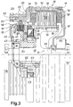
- Fig. 2
- eine Vorderansicht der elektrischen Maschine aus Fig. 1 mit einer Halterung für den Stator sowie der Seiltrommel und
- Fig. 3
- einen detaillierten seitlichen Teilschnitt der Maschine aus Fig. 1, bei der die erfindungsgemäße Anordnung und Ausbildung der Bremseinrichtung deutlich wird.
- Fig. 1
- a partial side section through an electrical machine according to the invention,
- Fig. 2
- a front view of the electrical machine of FIG. 1 with a holder for the stator and the cable drum and
- Fig. 3
- a detailed side partial section of the machine of FIG. 1, in which the arrangement and design of the braking device according to the invention is clear.
Die Fig. 1 zeigt eine erfindungsgemäße elektrische Maschine
11, die aus einem feststehenden Stator 12 und einem um den
Stator rotierenden Außenläufer 13 besteht. In der Fig. 1 ist
der Stator 12 an seinen beiden äußeren Enden an zwei Lagerböcken
14 gehaltert, mittels derer er auf einem Träger oder
eine Trägerplatte befestigt werden kann, vorzugsweise durch
Verschraubung. Selbstverständlich bieten sich sämtliche
Möglichkeiten an der Lagerung, abweichend von der in der Fig.
1 gezeigten, an.1 shows an electrical machine according to the
Mittels zweier Lager 16, die vorzugsweise als Rollenlager
bzw. Rillenkugellager ausgeführt sind, ist der Außenläufer 13
drehbar auf dem Stator 12 gelagert. Von dem rechten Lager 16
aus erstreckt sich eine vordere Gehäuseschale 17 zuerst
radial nach außen, um dann mit einem in etwa rechtwinkligen
Knick die Länge des Außenläufers vergrößernd ein Stück in
Richtung zu dem rechten Lagerbock 14 so weit zu verlaufen,
bis es diesen beinahe erreicht und von sich da an mit einem
erneuten Knick in radialer Richtung bis zu dem Außendurchmesser
erstreckt. In diesem Bereich ist die vordere Gehäuseschale
17 mit einer hinteren Gehäuseschale 18 durch stirnseitige
Gehäuseschrauben 19 verbunden. Die hintere Gehäuseschale
18 verläuft in axialer Richtung den Stator 12 übergreifend
über etwa zwei Drittel der Länge des Außenläufers 13, um dann
in eine Durchmesserverengung 20 überzugehen. Vom linken Ende
der Durchmesserverengung 20 läuft die Gehäuseschale radial
nach innen und mündet in eine Aufnahme 21 für das linke Lager
16.By means of two
Während die Außenseite des Abschnitts der hinteren Gehäuseschale
18 mit größerem Durchmesser in Umfangsrichtung verlaufende
Kühlrippen zur verbesserten Wärmeabfuhr aufweist,
ist auf den Abschnitt der Durchmesserverengung 20 eine
Seiltrommel 23 aufgesetzt. Mittels eines radial nach innen
reichenden Absatzes 24 liegt sie in einer umlaufenden Ecknut
der Durchmesserverengung 20 an, wobei die Stirnseite Bohrungen
zur Aufnahme von Seiltrommelschrauben 25, die in axialer
Richtung verlaufend in die hintere Gehäuseschale 18 eingreifen,
aufweist. Stirnseitig schließen Seiltrommel 23 und
hintere Gehäuseschale 18 den Außenläufer 13 in etwa bündig
ab. An ihrer Außenseite ist die Seiltrommel 23 mit mehreren
in Umfangsrichtung verlaufenden Rillen 27 versehen, die zur
Aufnahme eines Seils vorgesehen sind, an dem eine Fahrstuhlkabine
befestigt ist.While the outside of the section of the rear case shell
18 with a larger diameter extending in the circumferential direction
Has cooling fins for improved heat dissipation,
is a section of the
Der Stator 12 weist ausgehend von einer Welle 28, deren Enden
in den Lagerblöcken 14 gehaltert sind, im mittleren Bereich
einen radial abstehenden Träger 29 auf, der an seinem
Außenquerschnitt die Statorwicklung 30 trägt. Die Statorwicklung
30 ist in einem Blechpaket 31 angeordnet, welches
mittels einer durchgängigen Schraube 32 mit einem radial
abstehenden Befestigungsansatz 33 des Trägers 29 verschraubt
ist. Auf diese Weise stellt die Schraube 32 nicht nur den
Zusammenhalt des Blechpakets 31 sicher, sondern sorgt darüber
hinaus für die Drehmomentübertragung sowie eine exakte
Positionierung der Statorwicklung. Mehrere Spulen der Wicklung,
abhängig von der Polzahl, sind in Umfangsrichtung
verteilt angeordnet. Die Statorwicklung 30 nimmt den gesamten
Längsbereich des Außenläufers 13 im Bereich des weiten
Durchmessers ein und weist in axialer Richtung nur geringen
Abstand zu der Innenseite der vorderen Gehäuseschale 17 sowie
der hinteren Durchmesserverengung 20 auf.Starting from a
An der Innenseite des Gehäuses des Außenläufers 13 sind zu
der Ausdehnung des Blechpakets 31 korrespondierende Permanentmagnete
35 befestigt, beispielsweise eingeklebt, die
lediglich durch einen schmalen Luftspalt 36 vom Blechpaket
des Stators getrennt sind. Der Luftspalt 36 läßt sich besser
in der vergrößerten Darstellung in Fig. 3 erkennen. Über
einen zentralen Kanal 37, der gestrichelt dargestellt ist,
können die elektrischen Zuleitungen von der Statorwicklung 30
und Bremslüftspule mittels nicht dargestellter Kabel aus der
Maschine 11 in einem Kabelschlauch 38 herausgeführt und an
eine Motorsteuerung angeschlossen werden. Diese entspricht
einer üblichen Steuerung für einen elektronisch kommutierten
Motor.On the inside of the housing of the
An den Träger 29 schließt sich nach links an den Stator 12
die Bremseinrichtung 40 an, wobei die Betätigungseinrichtung
42 bis an den Träger 29 reicht. Für eine detailliertere
Darstellung der Bremse wird auf Fig. 3 verwiesen.The
In der axialen Einbuchtung der vorderen Gehäuseschale 17 ist
an der Gehäuseschale 17 bzw. an dem rechten Lagerbock 14 ein
Hohlwellen- bzw. Drehgeber 44 angeordnet, der Drehzahl und
Lage des Außenläufers 13 in Relation zu dem Stator ermittelt
und als Signale an eine Motorsteuerung gibt. Die Signale
werden auch für die Strom-Kommutierung benötigt.In the axial indentation of the
Die Fig. 2 zeigt eine Ansicht der erfindungsgemäßen Maschine
11 von der Stirnseite der hinteren Gehäuseschale 18. Es ist
deutlich zu sehen, wie das in Fig. 1 linke Ende der Welle 28
des Stators mit etwas abgeflachtem Querschnitt in einer
entsprechenden Aufnahmeausnehmung 45, die einen mittigen
senkrechten Schlitz 46 aufweist, aufgenommen ist. Oberhalb
der Aufnahmeausnehmung verläuft eine Befestigungsschraube 47
durch die beiden von dem Schlitz getrennten Abschnitte des
Lagerbocks 14 um diese gegeneinander zu verpressen und somit
das Wellenende sicher in der Aufnahmeausnehmung 45 zu halten.2 shows a view of the machine according to the
Auf den mit verringertem Durchmesser ausgeführten Abschnitt
20 der hinteren Gehäuseschale 18 ist die Seiltrommel 23 aufgesetzt,
wobei durch den Absatz 24 die Seiltrommelschrauben
25 geführt sind und in das Gehäuse des Außenläufers eingreifen.
Auf einem etwas kleineren Kreis als dem der Seiltrommelschrauben
25 sind Lagerbolzen 48 in den Außenläufer 13
geführt, deren Aufgabe weiter unten bei der Beschreibung der
Bremse erläutert wird.On the section with a reduced
Die Fig. 3 zeigt einen Schnitt ähnlich wie Fig. 1, allerdings
vergrößert und detaillierter. An der Fig. 3 soll vor allem
der Aufbau der Bremse erläutert werden. Die Bremse weist
einen Bremssattel 50 auf, der sowohl die Bremseinrichtung 40
als auch die Betätigungseinrichtung 42 trägt. An dem Bremssattel
50 sind sechs Statorbremslamellen 51 in Form von
Kreisringscheiben angeordnet, in deren radial inneren Teil
bzw. darin ausgebildete Ausnehmungen der Bremssattel eingreift
und sie dadurch bei axialer Beweglichkeit in Umfangsrichtung
drehfest gelagert sind. Derartige drehfeste Schiebelagerungen
können in Umfangsrichtung mehrfach verteilt an dem
Bremssattel zur Lagerung der Statorbremslamellen 51 vorgesehen
sein.3 shows a section similar to FIG. 1, however
enlarged and more detailed. 3 is above all
the structure of the brake are explained. The brake points
a
In die zwischen den Statorbremslamellen 51 gebildeten Zwischenräume
greifen Rotorbremslamellen 52 ein, die ähnlich wie
die Statorbremslamellen als Kreisringscheiben ausgeführt
sind. Ebenso kann die Lagerung, die gleichfalls eine axiale
Verschiebbarkeit sowie eine Verdrehsicherung aufweist,
aufgeführt sein. Dazu greift der Lagerbolzen 48 in den
Außenläufer 13 und in dem Querschnitt des Lagerbolzens
angepaßte Ausnehmungen im Außenbereich der Rotorbremslamellen
52 ein. Während in Umfangsrichtung die Bremslamellen 51 und
52 formschlüssig an ihrer Lagerung abgestützt sind, können
sie in axialer Richtung frei beweglich sein.In the spaces formed between the
Am linken Ende des Bremssattels 50 ist eine Abstützung 53 als
Anschlag für die von den Lamellen 51 und 52 gebildete Lamellenbremse
angebracht. Über eine in Umfangsrichtung im
wesentlichen durchgehende Andruckscheibe 54 wird die von
Schraubenfedern 56 aufgebrachte Andruckkraft auf die Bremslamellen
übertragen. Bevorzugt sind mehrere Schraubenfedern
56 als Schließvorrichtung in Umfangsrichtung verteilt angeordnet.At the left end of the
Die Andruckscheibe 54 ist wie die Lamellen axial frei beweglich,
wobei sie durch die im unteren Teil der Fig. 3
dargestellten Schraubbolzen 55 gelagert ist. Diese Schraubbolzen
55 weisen nur an ihrem vorderen, in den feststehenden
Bremssattel reichenden Ende ein Gewinde auf, während der
durch die Andruckscheibe 54 verlaufende Teil mit glattem
Außendurchmesser zur besseren axialen Beweglichkeit versehen
ist. Ebenso sind im unteren Teil der Fig. 3 durch den Bremssattel
50 reichende Langschrauben 57 dargestellt, die in
axialer Richtung durchgängig in den Träger 29 mit einem
Gewinde zur Befestigung der Bremse am Stator eingreifen.The
Zum Lösen der Bremse bzw. Überwinden der von den Schraubenfedern
56 aufgebrachten Andruckkraft ist eine Spule 59 in der
Betätigungseinrichtung 42 vorgesehen, die radial innerhalb
der Schraubenfedern 56 in Umfangrichtung verläuft. Bei
Versorgung der Spule 59 mit Spannung baut diese ein Magnetfeld
auf, das die Andruckscheibe 54 gegen die von den Schraubenfeden
56 ausgeübte Andruckkraft zu der Spule hinzieht.
Dadurch können sich die Bremslamellen des Stators und des
Rotors voneinander lösen. Die Andruckscheibe 54 kann in
mehrere Teile unterteilt sein, bevorzugt in zwei Teile, die
jeweils in etwa einen halbkreisförmigen Abschnitt einnehmen,
insbesondere bei einer Unterteilung eines Teils der Lamellen
in Umfangsrichtung in Sektoren. Mehrere Schraubenfedern 56
sowie eine Unterteilung der Bremse in mehrere sektorenförmige
Abschnitte kann die Sicherheit der Bremse erhöhen. So kann
beispielsweise bei einem Federbruch die Andruckkraft von den
restlichen Schraubenfedern übernommen werden.For releasing the brake or overcoming the from the coil springs
56 applied pressing force is a
Für den Aufzugsbetrieb ist es wichtig, daß die mechanischen Schließelemente permanent die Andruckkraft für die Bremse aufbringen und nur durch die Lösevorrichtung, beispielsweise in Form von Elektromagneten, zurückgehalten werden. Beispielsweise bei einem Stromausfall fällt die Bremse automatisch ein und hält den Fahrstuhl an.For elevator operation it is important that the mechanical Closing elements permanently apply the pressure for the brake apply and only through the release device, for example in the form of electromagnets. For example in the event of a power failure, the brake is released automatically and stops the elevator.
Zur Dektektierung des Zustands der Bremse ist ein Kontaktschalter
60 an dem Bremssattel 50 angeordnet, der durch eine
in der Andruckscheibe 54 verlaufende Justierschraube 61
auslösbar ist. Auf diese Weise kann entweder ein Lösen der
Bremse durch Anziehen der Andruckscheibe 54 gegen die Spule
59 detektiert werden oder ein Schließen der Bremse durch von
den Schraubenfedern 56 ausgelöste Anlage der Andruckscheibe
54 gegen die Bremslamellen. Durch eine mittels einer Schraubkappe
62 verschließbare Justieröffnung 63 kann die Justierschraube
61 von außen eingestellt bzw. nachjustiert werden.A contact switch is used to detect the condition of the
Claims (16)
Applications Claiming Priority (2)
| Application Number | Priority Date | Filing Date | Title |
|---|---|---|---|
| DE19815962 | 1998-04-09 | ||
| DE1998115962 DE19815962A1 (en) | 1998-04-09 | 1998-04-09 | Electrical machine, in particular for elevator drives |
Publications (2)
| Publication Number | Publication Date |
|---|---|
| EP0949743A2 true EP0949743A2 (en) | 1999-10-13 |
| EP0949743A3 EP0949743A3 (en) | 2000-07-19 |
Family
ID=7864128
Family Applications (1)
| Application Number | Title | Priority Date | Filing Date |
|---|---|---|---|
| EP99106572A Withdrawn EP0949743A3 (en) | 1998-04-09 | 1999-03-31 | Electrical machine, in particular for lift driving apparatus |
Country Status (3)
| Country | Link |
|---|---|
| EP (1) | EP0949743A3 (en) |
| JP (1) | JPH11299201A (en) |
| DE (1) | DE19815962A1 (en) |
Cited By (9)
| Publication number | Priority date | Publication date | Assignee | Title |
|---|---|---|---|---|
| EP1043261A3 (en) * | 1999-04-05 | 2002-07-17 | Mitsubishi Denki Kabushiki Kaisha | Elevator traction machine |
| EP0970912B1 (en) * | 1998-07-07 | 2004-11-03 | Hitachi, Ltd. | Elevator apparatus |
| WO2004099056A3 (en) * | 2003-05-05 | 2005-01-13 | Waagner Biro Germany Stage Sys | Cable winch |
| EP1796245A1 (en) * | 2005-12-09 | 2007-06-13 | Moteurs Leroy-Somer | Electric rotating machine with a brake which interact with two opposite surfaces |
| GB2485226A (en) * | 2010-11-08 | 2012-05-09 | Siemag Tecberg Gmbh | Integrated hoisting machine stator support |
| WO2015078691A3 (en) * | 2013-11-26 | 2015-09-11 | Siemens Aktiengesellschaft | Electrical machine, in particular electrical motor, and method for braking an electrical machine |
| CN115417279A (en) * | 2022-09-14 | 2022-12-02 | 浙江弗尔德驱动科技有限公司 | Inner rotor permanent magnet synchronous safe energy-saving traction machine |
| CN117674512A (en) * | 2024-02-03 | 2024-03-08 | 浙江弗尔德驱动科技有限公司 | New energy driving permanent magnet motor |
| CN119160741A (en) * | 2024-09-23 | 2024-12-20 | 日立电梯电机(广州)有限公司 | Traction machine |
Families Citing this family (10)
| Publication number | Priority date | Publication date | Assignee | Title |
|---|---|---|---|---|
| JP4606619B2 (en) * | 2001-03-07 | 2011-01-05 | 三菱電機株式会社 | Elevator hoisting machine |
| JP2002274770A (en) * | 2001-03-14 | 2002-09-25 | Mitsubishi Electric Corp | Gearless hoist for elevator |
| WO2007069312A1 (en) * | 2005-12-14 | 2007-06-21 | Mitsubishi Denki Kabushiki Kaisha | Electromagnet device for elevator |
| CN100590056C (en) * | 2006-02-22 | 2010-02-17 | 三菱电机株式会社 | Electromagnetic coil, brake device for elevator traction machine and manufacturing method thereof |
| DE102006032992A1 (en) * | 2006-07-17 | 2008-01-31 | Siemens Ag | Rotor for an electric machine and electric machine with such a rotor |
| DE102006056079A1 (en) * | 2006-11-28 | 2008-05-29 | Robert Bosch Gmbh | Electric motor i.e. lift motor, for use in e.g. conveyor, has brake device that is mechanically working brake device, which is not manually detachable in case of failure, and another brake device that is electrical brake device |
| JP5071306B2 (en) * | 2008-08-26 | 2012-11-14 | トヨタ自動車株式会社 | Drive device |
| DE102016223968A1 (en) * | 2016-12-01 | 2018-06-07 | Volkswagen Aktiengesellschaft | Assembled housing assembly for an electrical machine and manufacturing process |
| CN110436297B (en) | 2018-05-03 | 2022-04-29 | 奥的斯电梯公司 | Brake disc release device, barring device, elevator rescue kit and method |
| FR3110783B1 (en) * | 2020-05-19 | 2022-04-22 | Conductix Wampfler France | Device for winding/unwinding a link |
Family Cites Families (7)
| Publication number | Priority date | Publication date | Assignee | Title |
|---|---|---|---|---|
| US2974756A (en) * | 1958-03-03 | 1961-03-14 | Reliance Electric & Eng Co | Automatic reset brake release |
| US4921078A (en) * | 1988-02-18 | 1990-05-01 | Sommer Company | Electro-shear brake |
| DE4233759A1 (en) * | 1992-10-07 | 1994-04-14 | Blocher Elektromotorenwerk Dre | Gearless electric drive unit for personnel or goods elevator - has internal stator and external rotor carrying windlass cylinder for hoisting cable with concentrically mounted in-built brake |
| DE19500589A1 (en) * | 1995-01-11 | 1996-07-18 | Koersgen Heinz Norbert Dipl In | Gearless electric wheel-hub motor e.g. for wheel-chair |
| FI98724C (en) * | 1995-03-24 | 1997-08-11 | Kone Oy | Emergency drive device for elevator machinery |
| DE19511077C2 (en) * | 1995-03-25 | 1997-02-06 | Thyssen Aufzuege Gmbh | Gearless traction sheave carrier |
| FI103498B1 (en) * | 1996-09-05 | 1999-07-15 | Kone Corp | Arrangements to relieve the brake of a lift machine |
-
1998
- 1998-04-09 DE DE1998115962 patent/DE19815962A1/en not_active Withdrawn
-
1999
- 1999-01-12 JP JP516099A patent/JPH11299201A/en active Pending
- 1999-03-31 EP EP99106572A patent/EP0949743A3/en not_active Withdrawn
Cited By (13)
| Publication number | Priority date | Publication date | Assignee | Title |
|---|---|---|---|---|
| EP0970912B1 (en) * | 1998-07-07 | 2004-11-03 | Hitachi, Ltd. | Elevator apparatus |
| EP1043261A3 (en) * | 1999-04-05 | 2002-07-17 | Mitsubishi Denki Kabushiki Kaisha | Elevator traction machine |
| WO2004099056A3 (en) * | 2003-05-05 | 2005-01-13 | Waagner Biro Germany Stage Sys | Cable winch |
| EP1796245A1 (en) * | 2005-12-09 | 2007-06-13 | Moteurs Leroy-Somer | Electric rotating machine with a brake which interact with two opposite surfaces |
| FR2894731A1 (en) * | 2005-12-09 | 2007-06-15 | Leroy Somer Moteurs | ROTATING ELECTRIC MACHINE COMPRISING A BRAKE COMBINING WITH AT LEAST ONE BRAKING SURFACE EXTENDING NOT FULLY PERPENDICULAR TO THE AXIS OF ROTATION |
| GB2485226B (en) * | 2010-11-08 | 2016-12-21 | Siemag Tecberg Gmbh | Torque support for an integrated hoisting machine |
| GB2485226A (en) * | 2010-11-08 | 2012-05-09 | Siemag Tecberg Gmbh | Integrated hoisting machine stator support |
| WO2015078691A3 (en) * | 2013-11-26 | 2015-09-11 | Siemens Aktiengesellschaft | Electrical machine, in particular electrical motor, and method for braking an electrical machine |
| CN115417279A (en) * | 2022-09-14 | 2022-12-02 | 浙江弗尔德驱动科技有限公司 | Inner rotor permanent magnet synchronous safe energy-saving traction machine |
| CN115417279B (en) * | 2022-09-14 | 2024-03-26 | 浙江弗尔德驱动科技有限公司 | Inner rotor permanent magnet synchronous safe energy-saving traction machine |
| CN117674512A (en) * | 2024-02-03 | 2024-03-08 | 浙江弗尔德驱动科技有限公司 | New energy driving permanent magnet motor |
| CN117674512B (en) * | 2024-02-03 | 2024-05-17 | 浙江弗尔德驱动科技有限公司 | New energy driving permanent magnet motor |
| CN119160741A (en) * | 2024-09-23 | 2024-12-20 | 日立电梯电机(广州)有限公司 | Traction machine |
Also Published As
| Publication number | Publication date |
|---|---|
| JPH11299201A (en) | 1999-10-29 |
| DE19815962A1 (en) | 1999-10-14 |
| EP0949743A3 (en) | 2000-07-19 |
Similar Documents
| Publication | Publication Date | Title |
|---|---|---|
| EP0949743A2 (en) | Electrical machine, in particular for lift driving apparatus | |
| EP2005020B1 (en) | Electromagnetically released spring pressure brake in the form of a dual-circuit square brake | |
| DE3801716C2 (en) | differential gear | |
| DE69707674T2 (en) | ELECTROMAGNETICALLY RELEASABLE SAFETY FRICTION BRAKE | |
| DE69607100T2 (en) | Motor with reduction gear, assembly procedure and maintenance procedure of the same | |
| DE2747466C2 (en) | Adjustment device for changing the maximum possible distance between the magnet housing and the armature disk in the case of an electromagnetic brake | |
| EP3306786B1 (en) | Electric motor | |
| EP0944781A1 (en) | Electromechanical brake | |
| DE19733169A1 (en) | Electromagnetically released friction safety-brake for lift | |
| DE202015101779U1 (en) | Permanent magnet synchronous direct drive lifting device with a single-stage gear | |
| DE60204256T2 (en) | Torque releasable disc brake | |
| DE3330528C2 (en) | ||
| DE4225158A1 (en) | Electric machine system | |
| DE60205878T2 (en) | BRAKE COUPLING ARRANGEMENT | |
| DE10305434A1 (en) | Adapter for gear motor system has centrifugal jaws held together on coupling part by springs that can force brake lining against adapter housing friction surface, especially if critical value exceeded | |
| DE10310777A1 (en) | Electrical machine for direct drive of cable winch disc for elevator has coaxial pairs of electrical winding layers and cooperating permanent magnet layers | |
| DE4217099C1 (en) | ELECTRIC ROTATIONAL MOTOR WITH RETARDER BRAKE | |
| DE1173758B (en) | Electromotive adjustment device | |
| EP0729912A1 (en) | Chain hoist with brake actuated clutch | |
| EP1576713A1 (en) | Adapter, gear motor and modular gear motor system | |
| DE29510168U1 (en) | Spring pressure dual circuit braking system | |
| DE102021104253A1 (en) | Axial flow machine with braking device | |
| EP0729913B1 (en) | Chain hoist with brake actuated clutch | |
| DE19905390C1 (en) | Elevator drive with electric drive motor | |
| DE102009028151A1 (en) | Electrical adjusting drive for adjusting wheel control member of motor vehicle, has adjustable element for implementing axial movement during activation of drive such that adjustable element is in external contact with locking element |
Legal Events
| Date | Code | Title | Description |
|---|---|---|---|
| PUAI | Public reference made under article 153(3) epc to a published international application that has entered the european phase |
Free format text: ORIGINAL CODE: 0009012 |
|
| AK | Designated contracting states |
Kind code of ref document: A2 Designated state(s): AT BE CH DE ES FR GB IT LI NL |
|
| AX | Request for extension of the european patent |
Free format text: AL;LT;LV;MK;RO;SI |
|
| PUAL | Search report despatched |
Free format text: ORIGINAL CODE: 0009013 |
|
| AK | Designated contracting states |
Kind code of ref document: A3 Designated state(s): AT BE CH CY DE DK ES FI FR GB GR IE IT LI LU MC NL PT SE |
|
| AX | Request for extension of the european patent |
Free format text: AL;LT;LV;MK;RO;SI |
|
| RIC1 | Information provided on ipc code assigned before grant |
Free format text: 7H 02K 7/10 A, 7H 02K 7/102 B, 7B 66B 11/04 B, 7B 66B 5/02 B |
|
| 17P | Request for examination filed |
Effective date: 20010118 |
|
| AKX | Designation fees paid |
Free format text: AT BE CH CY DE DK ES FI FR LI |
|
| RBV | Designated contracting states (corrected) |
Designated state(s): AT BE CH DE ES FR GB IT LI NL |
|
| STAA | Information on the status of an ep patent application or granted ep patent |
Free format text: STATUS: THE APPLICATION IS DEEMED TO BE WITHDRAWN |
|
| 18D | Application deemed to be withdrawn |
Effective date: 20051001 |