EP0950810A2 - Diaphragm stopper construction for a high-pressure accumulator - Google Patents
Diaphragm stopper construction for a high-pressure accumulator Download PDFInfo
- Publication number
- EP0950810A2 EP0950810A2 EP98119379A EP98119379A EP0950810A2 EP 0950810 A2 EP0950810 A2 EP 0950810A2 EP 98119379 A EP98119379 A EP 98119379A EP 98119379 A EP98119379 A EP 98119379A EP 0950810 A2 EP0950810 A2 EP 0950810A2
- Authority
- EP
- European Patent Office
- Prior art keywords
- diaphragm
- pressure
- pressure accumulator
- recess portion
- plate
- Prior art date
- Legal status (The legal status is an assumption and is not a legal conclusion. Google has not performed a legal analysis and makes no representation as to the accuracy of the status listed.)
- Granted
Links
Images


Classifications
-
- F—MECHANICAL ENGINEERING; LIGHTING; HEATING; WEAPONS; BLASTING
- F02—COMBUSTION ENGINES; HOT-GAS OR COMBUSTION-PRODUCT ENGINE PLANTS
- F02M—SUPPLYING COMBUSTION ENGINES IN GENERAL WITH COMBUSTIBLE MIXTURES OR CONSTITUENTS THEREOF
- F02M59/00—Pumps specially adapted for fuel-injection and not provided for in groups F02M39/00 -F02M57/00, e.g. rotary cylinder-block type of pumps
- F02M59/02—Pumps specially adapted for fuel-injection and not provided for in groups F02M39/00 -F02M57/00, e.g. rotary cylinder-block type of pumps of reciprocating-piston or reciprocating-cylinder type
- F02M59/022—Pumps specially adapted for fuel-injection and not provided for in groups F02M39/00 -F02M57/00, e.g. rotary cylinder-block type of pumps of reciprocating-piston or reciprocating-cylinder type having an accumulator storing pressurised fuel during pumping stroke of the piston for subsequent delivery to the injector
-
- F—MECHANICAL ENGINEERING; LIGHTING; HEATING; WEAPONS; BLASTING
- F04—POSITIVE - DISPLACEMENT MACHINES FOR LIQUIDS; PUMPS FOR LIQUIDS OR ELASTIC FLUIDS
- F04B—POSITIVE-DISPLACEMENT MACHINES FOR LIQUIDS; PUMPS
- F04B11/00—Equalisation of pulses, e.g. by use of air vessels; Counteracting cavitation
- F04B11/0008—Equalisation of pulses, e.g. by use of air vessels; Counteracting cavitation using accumulators
- F04B11/0016—Equalisation of pulses, e.g. by use of air vessels; Counteracting cavitation using accumulators with a fluid spring
Definitions
- the present invention relates to a diaphragm stopper construction for a high-pressure accumulator which defines the limit of deformation of a flexible disk-shaped metal diaphragm disposed in a high-pressure vessel which supports and seals the perimeter portion of the metal diaphragm to form a high-pressure chamber.
- Diesel engines are the most widely known of the so-called "cylinder-injected” or “direct injection engines", engines in which fuel is injected into the engine cylinder, but in recent years cylinder-injected spark ignition engines (gasoline engines) have also been proposed. Cylinder-injected engines of this kind demand that fuel pressure surges be minimized to maintain sufficiently high fuel injection pressure and ensure stable injection.
- compact single-cylinder high-pressure fuel pumps have been proposed which are of simple construction and inexpensive to manufacture.
- surge absorption devices with metal bellows or diaphragms have been proposed to absorb these surges.
- Fig. 5 shows a high-pressure fuel supply system provided with a high-pressure accumulator which is a useful example of a surge absorption device to which the present invention can be applied.
- a delivery pipe 1 which is a fuel injection apparatus, is provided with a plurality of injectors 1a corresponding to the number of engine cylinders, which are not shown.
- a high-pressure fuel pump assembly 200 provided with a high-pressure fuel pump 3 is disposed between the delivery pipe 1 and a fuel tank 2.
- the delivery pipe 1 and the high-pressure fuel pump 3 are connected by a high-pressure fuel passage 4 and the high-pressure fuel pump 3 and the fuel tank 2 are connected by a low-pressure fuel passage 5.
- the high-pressure fuel passage 4 and the low-pressure fuel passage 5 compose a fuel passage connecting the delivery pipe 1 to the fuel tank 2.
- a filter 6 is disposed in the fuel intake of the high-pressure fuel pump 3 to prevent contamination by foreign matter above a certain size downstream from the fuel supply system, i.e., the high-pressure fuel pump 3, high-pressure accumulator 70, etc.
- a check valve 7 is disposed on the fuel discharge side of the high-pressure fuel pump 3.
- a drain 8 attached to the high-pressure fuel pump 3 returns to the fuel tank 2.
- a low-pressure fuel pump 10 is disposed at the end of the low-pressure fuel passage 5 close to the fuel tank 2.
- a filter 11 is disposed in the fuel intake of the low-pressure fuel pump 10.
- a check valve 12 is disposed in the low-pressure fuel passage 5 on the fuel discharge side of the low-pressure fuel pump 10.
- a low-pressure regulator 14 is disposed in the low-pressure fuel passage 5 between the high-pressure fuel pump 3 and the low-pressure fuel pump 10.
- a filter 15 is disposed in the fuel intake of the low-pressure regulator 14.
- a drain 16 attached to the low-pressure regulator 14 returns to the fuel tank 2.
- the high-pressure fuel pump 3 increases the pressure of the fuel supplied to it by the low-pressure fuel passage 5 and discharges it to the delivery pipe 1.
- a dumper 30 is disposed on the low-pressure fuel passage 5 side of the high-pressure fuel pump 3, i.e., the low-pressure side.
- a high-pressure accumulator 70 and a high-pressure regulator 32 are disposed on the high-pressure side of the high-pressure fuel pump 3.
- a drain 33 attached to the high-pressure regulator 32 returns to the fuel input side of the high-pressure fuel pump 3.
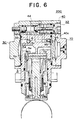
- Fig. 6 is a cross-section showing details of the high-pressure fuel pump assembly 200 when fully assembled, comprising the high-pressure fuel pump 3, dumper 30, high-pressure accumulator 70, high-pressure regulator 32, filter 6, and check valve 7.
- a recess portion 40c is formed in the casing 40 on the right-hand side of the diagram, and the high-pressure accumulator 70 is secured to the recess portion 40c.
- a discharge passage 4b which communicates with a discharge passage 4a is formed as a recess in the bottom of the recess portion 40c.
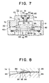
- Fig. 7 is a cross-section showing details of the high-pressure accumulator 70, which is a surge absorption device to which the present invention can be applied, and its fitted construction.
- the high-pressure accumulator 70 is provided with a case 85, which is a high-pressure vessel roughly the shape of a thick disk, a flexible disk-shaped metal diaphragm 86, supported by and sealed against the case 85 around its perimeter portion so that together they form a high-pressure chamber 71, and a disk-shaped plate 89, which is a stopper defining the limit of deformation of the diaphragm 86.
- the case 85 has a comparatively thin perimeter portion 72, which supports and seals the outer perimeter portion of the diaphragm 86 by a sealing weld, and a comparatively thick central portion 73, in which the high-pressure chamber 71 is formed.
- a male thread 91 is formed on the cylindrical outer surface of the peripheral portion 72, and a comparatively shallow saucer-shaped recess portion 74, which gradually deepens from the perimeter portion towards the central portion in a smooth curve to allow the diaphragm 86 to deform towards the high-pressure chamber 71, is formed in the portion in close contact with the diaphragm 86.
- An approximately-cylindrical recess portion 75 which communicates with the shallow saucer-shaped recess portion 74 at the central portion, is formed in the central portion 73 and, together with the saucer-shaped recess portion 74, forms the high-pressure chamber 71.
- a gas charge inlet 84 of circular cross-section about its central axis is formed in the ceiling portion of the high-pressure chamber 71 to introduce high-pressure gas to the high-pressure chamber 71 of the case 85 and seal it in, and a sealing device 87 is disposed therein to seal the gas charge inlet 84.
- the gas charge inlet 84 is provided with a small-diameter portion 76 of comparatively small diameter on the high-pressure side facing the high-pressure chamber 71, and a large-diameter portion 77 of comparatively large diameter on the low-pressure side facing the exterior of the case 85.
- a shoulder portion 78 is formed between the small-diameter portion 76 and the large-diameter portion 77, and a female thread is formed on the inner surface of the small-diameter portion 76.
- An annular groove 79 is disposed in the shoulder portion 78 to accommodate an O-ring 88.
- the sealing device 87 is a plug member inserted into the described gas charge inlet 84 and has a large-diameter portion 81, which is inserted into the large-diameter portion 77 of the gas charge inlet 84, and a small-diameter portion 80, which has a thread around its outside surface which engages the female thread of the small-diameter portion 76, and the large-diameter portion 81 inserted into the gas charge inlet 84 presses on the O-ring 88 and seals the gas charge inlet 84.
- the perimeter portion of the diaphragm 86 is sealed and supported on the outer perimeter portion of the case 85 by a weld portion 82 made by an electron beam or the like, but in addition a saucer-shaped plate 89 is disposed on the diaphragm 86 as a stopper to define the limit of deformation of the diaphragm 86, and the plate 89 is also fastened around its circumference by the weld portion 82.
- a recess portion 83 shaped like one side of a convex lens is formed on the inner face of the plate 89, which gradually deepens from the outer perimeter portion of the diaphragm 86 towards the center, and communicating holes 90 are formed as fuel channels which communicate with the recess portion 83.
- the case 85, the metal diaphragm 86, and the plate 89 are all hermetically sealed and bonded to each other around their outer perimeter portions by welding with an electron beam, or the like.
- the space sealed between the metal diaphragm 86 and the case 85 is charged with a high-pressure gas such as nitrogen.
- the male thread 91 engages the thread in the case 40, and at the same time, the end surface 92 of the plate 89 of the high-pressure accumulator 70 and the O-ring 51 slide past each other around the circumference of the O-ring 51 and generate friction.
- the high-pressure accumulator 70 is secured to the case 40, and a seal is formed between the end surface 92 and the O-ring 51.
- the high-pressure accumulator 70 constructed in this way, absorbs surges in the pressure of the fuel discharged by the discharge passage 4b. That is, while fuel is being discharged through the discharge passage 4b, surges occur in the discharge passage 4b, for example, when the high-pressure fuel pump is operating.
- the volume of the high-pressure chamber 71 varies in response to changes caused by the surges until the pressure of the high-pressure gas in the high-pressure chamber 71 reaches equilibrium with the pressure in the discharge passage 4b through the diaphragm 86.
- the diaphragm 86 when the pressure in the discharge passage 4b rises, the diaphragm 86 is deformed such that the volume of the high-pressure chamber 71 decreases and the volume of the discharge passage 4b increases, and so the pressure in the discharge passage 4b decreases and surging is reduced.
- the supply of fuel from the high-pressure fuel pump 3 also stops, and the fuel pressure in the lens-shaped recess 83 on the plate 89 side gently decreases. For that reason, the diaphragm 86 is displaced from its position during normal operation shown in the diagram due to the pressure of the gas in the high-pressure chamber 71, but to prevent damage and wear on the diaphragm 86, a diaphragm stopper construction is employed having a curve such that when the diaphragm deforms a certain amount, it comes into contact with the surface of curve of the lens-shaped recess 83 on the plate 89 and does not deform any further, and thus excessive stress does not concentrate on the diaphragm 86.
- a filter 6 is disposed on the upstream side of the high-pressure accumulator 70 to prevent the passage downstream of matter above a certain size.
- foreign matter below a certain size passes through the filter 6, and so contamination of the lens-shaped recess 83 of the high-pressure accumulator 70 by foreign matter below a certain size through the discharge passage 4b and communicating holes 90 together with fuel cannot be avoided.
- an object of the present invention is to provide a diaphragm stopper construction for a high-pressure accumulator which prevents deformation or damage to a diaphragm due to the catching of foreign matter.
- a diaphragm stopper construction for a high-pressure accumulator having a gentle slope which defines the limit of deformation of a flexible disk-shaped metal diaphragm disposed in a high-pressure vessel which supports and seals the perimeter portion of the diaphragm to form a high-pressure chamber therebetween, is provided with an annular recess portion difined in the gentle slope to extend in close proximity to, parallel to, and radially inside of the secured portion of the perimeter portion of the diaphragm.
- the present invention is characterized in that the high-pressure accumulator may be disposed downstream of a filter and the annular recess portion may have a cavity capable of receiving foreign matter of the size which passes through the filter.
- the present invention is characterized in that the annular recess portion may be a groove of a substantially rectangular cross-section.
- the present invention is characterized in that the annular recess portion may have a substantially terraced cross-section having a flat surface substantially parallel to the secured portion of the diaphragm and a wall positioned at the outer edge of the flat surface which rises up gently at an angle from the flat surface.
- Fig. 1 shows a cross-section of the high-pressure accumulator 100 and its fitted construction to which a stopper construction which is an embodiment of the present invention has been applied.
- Fig. 2 is an enlargement of the portion A in Fig. 1. Apart from the shape of the plate 101, the rest of the construction in Fig. 1 is the same as in Fig. 5 and further explanation of the same portions will be omitted.
- a gentle slope 103 which defines the limit of deformation of a flexible disk-shaped metal diaphragm 86 disposed in a case 85 which is a high-pressure vessel which supports and seals the perimeter portion 102 of the diaphragm 86 to form a high-pressure chamber 71 performs the function of a diaphragm stopper for a high-pressure accumulator 100.
- the diaphragm 86 is supported and sealed by the case 85 and a plate 101 and has a secured portion 104 which forms a roughly doughnut-shaped flat surface which is not displaced even if the pressure in the high-pressure chamber 71 fluctuates.
- a rectangular groove 105 is disposed which has a rectangular cross-section 1 mm or less wide and which is an annular recess portion formed around the circumference of the plate 101 in close proximity to and radially inside the innermost secured edge S of the secured portion 104, for example, at a position 2 mm inside from S.
- the size of the rectangular groove 105 is determined by the size of the foreign matter contained in the fuel which flows into the recess portion 83. In other words, the size of the rectangular groove 105 is determined such that even if the diaphragm 86 is displaced and comes into contact with the gentle slope 103 of the plate 101, foreign matter can be received in the rectangular groove 105.
- the size of the rectangular groove 105 can also be determined by the size of the mesh which sets the limit of filtration of the filter 6 upstream from the high-pressure accumulator 70 to which the present invention can be applied, in the fuel supply passage shown in Fig. 5.
- the size of the rectangular groove 105 can be set in consideration of contamination by foreign matter of approximately 30 ⁇ m or less.
- Fig. 3 shows a cross-section of the high-pressure accumulator 100 and its fitted construction to which a stopper construction which is an embodiment of the present invention has been applied.
- Fig. 4 is an enlargement of the portion B in Fig. 3. Apart from the shape of the plate 121, the rest of the construction in Fig. 3 is the same as that shown in Fig. 1 and further explanation of the same portions will be omitted.
- groove 105 disposed in the gentle slope 103 in Fig. 2 has a rectangular cross-section
- this embodiment shown in Fig. 4 has a terraced recess portion 125 disposed in a gentle slope 123.
- the terraced recess portion 125 comprises a flat surface 125a substantially almost parallel to the secured portion 104 of the diaphragm 86 and a wall 125b disposed on the outer edge of the flat surface 125a which rises up gently at an angle from the flat surface 125a.
- the wall 125b is positioned in close proximity to and radially inside the innermost secured edge S of the secured portion 104.
- the terraced recess portion 125 can be simultaneously formed in the machining process which forms the gentle slope of the plate 121.
- a diaphragm stopper construction for a high-pressure accumulator having a gentle slope which defines the limit of deformation of a flexible disk-shaped metal diaphragm disposed in a high-pressure vessel which supports and seals the perimeter portion of the diaphragm to form a high-pressure chamber therebetween is provided with an annular recess portion difined in the gentle slope to extend in close proximity to, parallel to, and radially inside of the secured portion of the perimeter portion of the diaphragm, and so even if the fuel is contaminated by foreign matter, the foreign matter is received in the rectangular groove, so that no damage is caused by the foreign matter which is caught in the slight gap between the diaphragm and the plate and which deforms the diaphragm as in the conventional design.
- the high-pressure accumulator is disposed downstream of a filter and the annular recess portion has a cavity capable of receiving foreign matter of the size which passes through the filter, and so by providing a cavity appropriate to the size of the foreign matter which is contained in the fuel and flows into the high-pressure accumulator, it is possible to effectively prevent the catching of foreign matter by the diaphragm.
- the annular recess portion has a substantially terraced shape having a flat surface substantially parallel to the secured portion of the diaphragm and a wall positioned at the outer edge of the flat surface which rises up from the flat surface, and so, in addition to the above effects, when the diaphragm is no longer in contact, the foreign matter which has entered the recess portion is easily expelled from the recess portion.
- the recess portion can be simultaneously formed in the machining process which forms the gentle slope of the plate.
Landscapes
- Engineering & Computer Science (AREA)
- Mechanical Engineering (AREA)
- General Engineering & Computer Science (AREA)
- Chemical & Material Sciences (AREA)
- Combustion & Propulsion (AREA)
- Diaphragms And Bellows (AREA)
- Supply Devices, Intensifiers, Converters, And Telemotors (AREA)
- Fuel-Injection Apparatus (AREA)
Abstract
Description
Claims (6)
- A diaphragm stopper construction for a high-pressure accumulator having a gentle slope which defines the limit of deformation of a flexible disk-shaped metal diaphragm disposed in a high-pressure vessel which supports and seals the perimeter portion of said diaphragm to form a high-pressure chamber therebetween,
characterized by an annular recess portion difined in said gentle slope to extend in close proximity to, parallel to, and radially inside of the secured portion of the perimeter portion of said diaphragm. - The diaphragm stopper construction for a high-pressure accumulator according to Claim 1, characterized in that said high-pressure accumulator is disposed downstream of a filter and said annular recess portion has a cavity capable of receiving foreign matter of the size which passes through said filter.
- The diaphragm stopper construction for a high-pressure accumulator according to Claim 1, characterized in that said annular recess portion is a groove of a substantially rectangular cross-section.
- The diaphragm stopper construction for a high-pressure accumulator according to Claim 2, characterized in that said annular recess portion is a groove of a substantially rectangular cross-section.
- The diaphragm stopper construction for a high-pressure accumulator according to Claim 1, characterized in that said annular recess portion has a substantially terraced cross-section having a flat surface substantially parallel to the secured portion of said diaphragm and a wall positioned at the outer edge of said flat surface which rises up gently at an angle from said flat surface.
- The diaphragm stopper construction for a high-pressure accumulator according to Claim 2, characterized in that said annular recess portion has a substantially terraced cross-section having a flat surface substantially parallel to the secured portion of said diaphragm and a wall positioned at the outer edge of said flat surface which rises up gently at an angle from said flat surface.
Applications Claiming Priority (2)
| Application Number | Priority Date | Filing Date | Title |
|---|---|---|---|
| JP10506398 | 1998-04-15 | ||
| JP10506398A JP3455419B2 (en) | 1998-04-15 | 1998-04-15 | Diaphragm stopper structure of high pressure accumulator |
Publications (3)
| Publication Number | Publication Date |
|---|---|
| EP0950810A2 true EP0950810A2 (en) | 1999-10-20 |
| EP0950810A3 EP0950810A3 (en) | 2000-08-09 |
| EP0950810B1 EP0950810B1 (en) | 2004-06-09 |
Family
ID=14397513
Family Applications (1)
| Application Number | Title | Priority Date | Filing Date |
|---|---|---|---|
| EP98119379A Expired - Lifetime EP0950810B1 (en) | 1998-04-15 | 1998-10-14 | Diaphragm stopper construction for a high-pressure accumulator |
Country Status (4)
| Country | Link |
|---|---|
| US (1) | US6098991A (en) |
| EP (1) | EP0950810B1 (en) |
| JP (1) | JP3455419B2 (en) |
| DE (1) | DE69824391T2 (en) |
Cited By (2)
| Publication number | Priority date | Publication date | Assignee | Title |
|---|---|---|---|---|
| EP1403509A3 (en) * | 2002-09-27 | 2005-01-05 | Robert Bosch Gmbh | Pressure limiting device and fuel system with such a pressure limiting device |
| EP1365142A3 (en) * | 2002-05-24 | 2006-03-15 | Hitachi, Ltd. | High-pressure fuel pump |
Families Citing this family (4)
| Publication number | Priority date | Publication date | Assignee | Title |
|---|---|---|---|---|
| JP2005163564A (en) * | 2003-11-28 | 2005-06-23 | Toyota Industries Corp | Diaphragm device |
| JP4792598B2 (en) * | 2008-03-24 | 2011-10-12 | 株式会社日本製鋼所 | Hydrogen permeation module and method of use thereof |
| US12227047B2 (en) | 2022-04-22 | 2025-02-18 | DRiV Automotive Inc. | Bellows accumulator fixation apparatus for suspension dampers |
| US12188540B2 (en) | 2022-04-22 | 2025-01-07 | DRiV Automotive Inc. | Method of assembling a bellows accumulator for suspension dampers |
Family Cites Families (10)
| Publication number | Priority date | Publication date | Assignee | Title |
|---|---|---|---|---|
| JPS5468513A (en) * | 1977-11-09 | 1979-06-01 | Matsushita Electric Ind Co Ltd | Water accumulator |
| US4253675A (en) * | 1979-11-01 | 1981-03-03 | Bellofram Corporation | Improvements of sealed shafts |
| JPS56120401U (en) * | 1980-02-18 | 1981-09-14 | ||
| US4644847A (en) * | 1983-05-16 | 1987-02-24 | Fluitron, Inc. | Reduction of failure incidence of metallic diaphragms for compressors |
| JPH0722367Y2 (en) * | 1988-04-11 | 1995-05-24 | 自動車機器株式会社 | Brake booster |
| JPH02225801A (en) * | 1989-02-27 | 1990-09-07 | Nhk Spring Co Ltd | Accumulator |
| US5142964A (en) * | 1990-04-05 | 1992-09-01 | Jidosha Kiki Co., Ltd. | Negative pressure booster |
| US5261317A (en) * | 1992-12-21 | 1993-11-16 | Carrier Corporation | Bellows with dirt collecting recesses |
| JPH07151101A (en) * | 1993-11-29 | 1995-06-13 | Kazuo Sugimura | Vessel having spiral diaphragm contact surface |
| DE19544223B4 (en) * | 1995-11-28 | 2005-11-24 | Robert Bosch Gmbh | Vibration damper for damping fluid vibrations in a hydraulic, slip-controlled braking system of motor vehicles |
-
1998
- 1998-04-15 JP JP10506398A patent/JP3455419B2/en not_active Expired - Lifetime
- 1998-10-14 EP EP98119379A patent/EP0950810B1/en not_active Expired - Lifetime
- 1998-10-14 DE DE69824391T patent/DE69824391T2/en not_active Expired - Lifetime
- 1998-11-02 US US09/184,016 patent/US6098991A/en not_active Expired - Lifetime
Cited By (5)
| Publication number | Priority date | Publication date | Assignee | Title |
|---|---|---|---|---|
| EP1365142A3 (en) * | 2002-05-24 | 2006-03-15 | Hitachi, Ltd. | High-pressure fuel pump |
| US7152583B2 (en) | 2002-05-24 | 2006-12-26 | Hitachi, Ltd. | High-pressure fuel pump |
| EP1835169A2 (en) | 2002-05-24 | 2007-09-19 | Hitachi, Ltd. | High-pressure fuel pump |
| EP1835169A3 (en) * | 2002-05-24 | 2007-09-26 | Hitachi, Ltd. | High-pressure fuel pump |
| EP1403509A3 (en) * | 2002-09-27 | 2005-01-05 | Robert Bosch Gmbh | Pressure limiting device and fuel system with such a pressure limiting device |
Also Published As
| Publication number | Publication date |
|---|---|
| US6098991A (en) | 2000-08-08 |
| DE69824391T2 (en) | 2005-06-16 |
| JP3455419B2 (en) | 2003-10-14 |
| DE69824391D1 (en) | 2004-07-15 |
| JPH11303802A (en) | 1999-11-02 |
| EP0950810A3 (en) | 2000-08-09 |
| EP0950810B1 (en) | 2004-06-09 |
Similar Documents
| Publication | Publication Date | Title |
|---|---|---|
| US8366421B2 (en) | Fluid pressure pulsation damper mechanism and high-pressure fuel pump equipped with fluid pressure pulsation damper mechanism | |
| US6079450A (en) | Metal diaphragm type pulsation absorber for high-pressure fuel pump | |
| EP0911512B1 (en) | Cylinder injection high-pressure fuel pump | |
| US6223725B1 (en) | High-pressure fuel supply assembly | |
| US10859048B2 (en) | High-pressure fuel pump | |
| US20030106535A1 (en) | Fuel rail pulse damper | |
| EP0947691B1 (en) | Diaphragm stopper construction for a high-pressure accumulator | |
| EP0950810B1 (en) | Diaphragm stopper construction for a high-pressure accumulator | |
| US6213094B1 (en) | High-pressure fuel pump | |
| EP0947745B1 (en) | Sealing device for a high-pressure vessel | |
| EP0950809B1 (en) | High-pressure accumulator | |
| US6971859B2 (en) | Diaphragm unit | |
| CN115398090B (en) | High-pressure fuel feed pump and manufacturing method | |
| CN113167195A (en) | Device for injecting water into a combustion chamber or into an intake system of an internal combustion engine | |
| US7124739B2 (en) | Fuel pressure adjusting apparatus | |
| US6190139B1 (en) | Filter for piston type high-pressure fuel pump | |
| EP0911513A1 (en) | Cylinder injection high-pressure fuel pump | |
| JP4379389B2 (en) | High pressure fuel supply pump | |
| JP3355699B2 (en) | Accumulator | |
| JP7084753B2 (en) | Valve unit fixed structure | |
| JP3685405B2 (en) | High pressure accumulator | |
| CN216866868U (en) | Automatic flow regulating device for oil delivery pump of common rail system | |
| KR20190140406A (en) | High-pressure fuel pump | |
| CN112727653B (en) | Accumulator and fuel system | |
| JPH10227269A (en) | Fuel pressure fluctuation reduction device |
Legal Events
| Date | Code | Title | Description |
|---|---|---|---|
| PUAI | Public reference made under article 153(3) epc to a published international application that has entered the european phase |
Free format text: ORIGINAL CODE: 0009012 |
|
| AK | Designated contracting states |
Kind code of ref document: A2 Designated state(s): DE FR IT |
|
| AX | Request for extension of the european patent |
Free format text: AL;LT;LV;MK;RO;SI |
|
| PUAL | Search report despatched |
Free format text: ORIGINAL CODE: 0009013 |
|
| AK | Designated contracting states |
Kind code of ref document: A3 Designated state(s): AT BE CH CY DE DK ES FI FR GB GR IE IT LI LU MC NL PT SE |
|
| AX | Request for extension of the european patent |
Free format text: AL;LT;LV;MK;RO;SI |
|
| 17P | Request for examination filed |
Effective date: 20000726 |
|
| AKX | Designation fees paid |
Free format text: DE FR IT |
|
| 17Q | First examination report despatched |
Effective date: 20030429 |
|
| GRAP | Despatch of communication of intention to grant a patent |
Free format text: ORIGINAL CODE: EPIDOSNIGR1 |
|
| GRAS | Grant fee paid |
Free format text: ORIGINAL CODE: EPIDOSNIGR3 |
|
| GRAA | (expected) grant |
Free format text: ORIGINAL CODE: 0009210 |
|
| AK | Designated contracting states |
Kind code of ref document: B1 Designated state(s): DE FR IT |
|
| REF | Corresponds to: |
Ref document number: 69824391 Country of ref document: DE Date of ref document: 20040715 Kind code of ref document: P |
|
| ET | Fr: translation filed | ||
| PLBE | No opposition filed within time limit |
Free format text: ORIGINAL CODE: 0009261 |
|
| STAA | Information on the status of an ep patent application or granted ep patent |
Free format text: STATUS: NO OPPOSITION FILED WITHIN TIME LIMIT |
|
| 26N | No opposition filed |
Effective date: 20050310 |
|
| PGFP | Annual fee paid to national office [announced via postgrant information from national office to epo] |
Ref country code: IT Payment date: 20081029 Year of fee payment: 11 |
|
| PGFP | Annual fee paid to national office [announced via postgrant information from national office to epo] |
Ref country code: FR Payment date: 20081014 Year of fee payment: 11 |
|
| REG | Reference to a national code |
Ref country code: FR Ref legal event code: ST Effective date: 20100630 |
|
| PG25 | Lapsed in a contracting state [announced via postgrant information from national office to epo] |
Ref country code: FR Free format text: LAPSE BECAUSE OF NON-PAYMENT OF DUE FEES Effective date: 20091102 |
|
| PG25 | Lapsed in a contracting state [announced via postgrant information from national office to epo] |
Ref country code: IT Free format text: LAPSE BECAUSE OF NON-PAYMENT OF DUE FEES Effective date: 20091014 |
|
| PGFP | Annual fee paid to national office [announced via postgrant information from national office to epo] |
Ref country code: DE Payment date: 20171011 Year of fee payment: 20 |
|
| REG | Reference to a national code |
Ref country code: DE Ref legal event code: R071 Ref document number: 69824391 Country of ref document: DE |