EP0959155A2 - Bale opening machine - Google Patents
Bale opening machine Download PDFInfo
- Publication number
- EP0959155A2 EP0959155A2 EP99108069A EP99108069A EP0959155A2 EP 0959155 A2 EP0959155 A2 EP 0959155A2 EP 99108069 A EP99108069 A EP 99108069A EP 99108069 A EP99108069 A EP 99108069A EP 0959155 A2 EP0959155 A2 EP 0959155A2
- Authority
- EP
- European Patent Office
- Prior art keywords
- feed table
- riser
- bale
- bales
- conveyor belt
- Prior art date
- Legal status (The legal status is an assumption and is not a legal conclusion. Google has not performed a legal analysis and makes no representation as to the accuracy of the status listed.)
- Granted
Links
- 239000004744 fabric Substances 0.000 claims abstract description 37
- 239000010902 straw Substances 0.000 claims abstract description 15
- 244000025254 Cannabis sativa Species 0.000 claims abstract description 11
- 235000012766 Cannabis sativa ssp. sativa var. sativa Nutrition 0.000 claims abstract description 11
- 235000012765 Cannabis sativa ssp. sativa var. spontanea Nutrition 0.000 claims abstract description 11
- 235000009120 camo Nutrition 0.000 claims abstract description 11
- 235000005607 chanvre indien Nutrition 0.000 claims abstract description 11
- 239000011487 hemp Substances 0.000 claims abstract description 11
- 241000208202 Linaceae Species 0.000 claims abstract description 10
- 235000004431 Linum usitatissimum Nutrition 0.000 claims abstract description 10
- 238000000034 method Methods 0.000 claims abstract description 7
- 239000000463 material Substances 0.000 claims description 31
- 239000002657 fibrous material Substances 0.000 claims description 10
- 238000004140 cleaning Methods 0.000 claims description 7
- 239000000428 dust Substances 0.000 claims description 4
- 239000002994 raw material Substances 0.000 claims description 3
- 238000000605 extraction Methods 0.000 claims description 2
- 230000005484 gravity Effects 0.000 claims description 2
- 230000002093 peripheral effect Effects 0.000 claims 1
- 230000000630 rising effect Effects 0.000 abstract description 12
- 238000005096 rolling process Methods 0.000 description 3
- 230000000694 effects Effects 0.000 description 2
- 229920000742 Cotton Polymers 0.000 description 1
- 238000009825 accumulation Methods 0.000 description 1
- 230000001174 ascending effect Effects 0.000 description 1
- 230000000881 depressing effect Effects 0.000 description 1
- 238000004090 dissolution Methods 0.000 description 1
- 230000029142 excretion Effects 0.000 description 1
- 239000000835 fiber Substances 0.000 description 1
- 238000009499 grossing Methods 0.000 description 1
- 238000003306 harvesting Methods 0.000 description 1
- 239000003999 initiator Substances 0.000 description 1
- 230000003993 interaction Effects 0.000 description 1
- 238000000926 separation method Methods 0.000 description 1
- 230000035939 shock Effects 0.000 description 1
- 239000004753 textile Substances 0.000 description 1
- 238000010257 thawing Methods 0.000 description 1
- 239000002699 waste material Substances 0.000 description 1
Images
Classifications
-
- A—HUMAN NECESSITIES
- A01—AGRICULTURE; FORESTRY; ANIMAL HUSBANDRY; HUNTING; TRAPPING; FISHING
- A01D—HARVESTING; MOWING
- A01D87/00—Loaders for hay or like field crops
- A01D87/12—Loaders for sheaves, stacks or bales
- A01D87/127—Apparatus for handling, loading or unrolling round bales
-
- A—HUMAN NECESSITIES
- A01—AGRICULTURE; FORESTRY; ANIMAL HUSBANDRY; HUNTING; TRAPPING; FISHING
- A01F—PROCESSING OF HARVESTED PRODUCE; HAY OR STRAW PRESSES; DEVICES FOR STORING AGRICULTURAL OR HORTICULTURAL PRODUCE
- A01F29/00—Cutting apparatus specially adapted for cutting hay, straw or the like
- A01F29/005—Cutting apparatus specially adapted for cutting hay, straw or the like for disintegrating and cutting up bales of hay, straw or fodder
-
- A—HUMAN NECESSITIES
- A01—AGRICULTURE; FORESTRY; ANIMAL HUSBANDRY; HUNTING; TRAPPING; FISHING
- A01D—HARVESTING; MOWING
- A01D87/00—Loaders for hay or like field crops
- A01D87/12—Loaders for sheaves, stacks or bales
- A01D87/127—Apparatus for handling, loading or unrolling round bales
- A01D2087/128—Devices for unrolling or breaking round bales
Definitions
- the invention relates to a bale opener and a method for opening bales of flat or hemp straw, in particular of round bales, with the bale opener essentially one horizontally aligned feed table with an endless conveyor belt and an adjoining feed table with Endless conveyor belt, which has the material to be opened a riser cloth that feeds the material to a stripping device conveyed to the subsequent cleaning machine to submit.
- the for fiber such as Known cotton bale opener are for opening bales of flax or hemp straw or similar raw materials, and not only because of different and finer opening tools, but because completely different material and different structure of the bales.
- the invention has for its object a bale opener and a method for opening bales of flax or Hemp straw and similar raw materials to create the particular one is suitable for opening round bales.
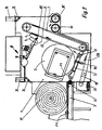
- Figure 1 is equipped with an endless conveyor belt 2 Template table 1 for feeding the bales 3, 31 from flax or Hemp straw shown.
- This template table 1 follows a feed table housed in a housing 4 of the bale opener 5, which is also drivable in the direction of arrow F1 Has conveyor belt 52.
- the feed table 5 is against a riser in the conveying direction 7 inclined downwards.
- the round bale rolls through this inclination 3 by its gravity in the open position shown and is there under the necessary for processing the bale 3 System pressure held against the riser 7, during the bale 31 on the delivery table in the waiting position remains.
- the inclination is preferably about 20 °.
- a separation device follows the feed table 5 6, which serves foreign parts, but also shives, in particular but to excrete stones and the like to be in the fiber material unwanted foreign parts and damage to the riser cloth 7 and the following opening tools.
- the angle of inclination of the riser 7 is determined by the Determines the type of material to be processed. The less that Material sticks to the riser cloth and the less it dissolves is, the flatter the part of the material gripping Riser cloth and vice versa. The riser cloth can be too this purpose can be adjusted in its increase.
- the rising slat 7 has extending over its working width Needle strips on, usually at a distance are arranged from 50 to 70 mm.
- the one on the needle bars attached needles have a height of 20 to 40 mm and are at an angle of approximately 45 ° in the conveying direction employed. Depending on the material to be processed, this can Riser cloth 7 interchangeable with pinned and non-pinned Last as well as with needle bars of different needle lengths be equipped.
- the Back rake 8 an elliptical movement, which is shown in FIG is indicated by the two curves a and b.
- Curve b shows the movement the rear rake rake 8 at a further distance while the curve a against the back rake 8 against the riser cloth 7 indicates.
- the rising slat 7 is in the area of the downward movement Trums assigned a stripper roller 10 with a Counter roll 10 'forms a pair of delivery rolls. Using the scraper roller 10 the opened fiber material from the riser cloth 7 detached and by the forming a pair of delivery rollers Rollers 10 and 10 'a material store or the subsequent one Machine fed. Through this from the stripper roller 10 and the counter roller 10 'formed delivery roller pair not only the material from the returning strand of the Riser slat 7 detached but it also takes place another equalization of those delivered by the bale opener Amount of material. It prevents larger ones Amounts of the stripped and also fleece-like from the riser cloth 7 hanging material falling off and uncontrolled be passed on.
- the separator 6 has essentially the shape of a Fork or comb that is spaced at intervals of approximately 100 to 150 mm has comb or fork tines, the free length of which is about 120 mm.
- the separating device 6 is uni a distance horizontal axis 61 lying on the riser 7 preferably against spring force away from the riser 7 pivotable upward, so that the device is blocked in the event that 7 or also in the prongs of the separating device 6 fiber material got stuck.
- a conveyor belt 15 extending over the space below the feed table 5.
- This transport hand 15 catches not only the separated foreign parts, but also all dust and dirt that results from the opening of the bales in the area of the feed table.
- the transport movement is opposite to the feed table 5 in the direction of arrow F 2 .
- the conveyor belt 15 transfers the collected dirt and waste to the cross conveyor belt 11, which provides transportation from the machine.
- a pneumatic conveying device can also be provided, which works with suction or blown air or in combination.
- the excretion device works as follows: About the The feed table 5 brings the material to be opened into the area of the riser 7 and also in the gap between the Feeding table and rising riser 7, from which also through the dissolution of the bale 3 material and thus foreign parts also fall down. The distances between the forks are chosen so that the foreign parts fall through, but the straw-like Material slides over it and from the riser 7 can be detected. To damage the riser cloth 7 to be avoided if there is a gap between it and the rake 6 If material has got caught, it can move in the direction of conveyance of the riser 7 dodge and folds up into the 6 ' designated position. By a restoring force, for example a spring, the rake 6 is back in its, the gap closing position moved back. Through this evasive movement is damage to the riser 7 or of the rake 6 prevented.
- a restoring force for example a spring
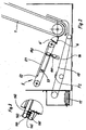
- the bale opener according to the invention works as follows: A bale 3 is placed on the feed table 1. Through the endless conveyor belt 2 at the end it is transferred to the feed table 5, i.e. the bale 3 rolls on its own weight inclined feed table 5 against the riser 7. Under the Conveyor belt 52 of the feed table 5 is a sensor plate 51 arranged, on which the bale 3 presses by its weight.
- This sensor plate 51 is mounted on two cross members 142, whereby it can pivot about an axis 53 while by loading the carrier 142 against one on the carrier 141 presses buffer spring 143 fixed in the machine.
- This spring 143 is part of a sensor device 14, to the a fuse support 145 and a sensor switch 144 belong.
- the fuse support 45 ensures that even at large bale weights and shock loads of the Feed table 5 and the sensor plate 51 damage to the Sensor switch 144 is avoided.
- the sensor switch 144 By depressing the sensor plate 51, the sensor switch 144 operated and the endless conveyor belt 2 of the table 1 stopped, so that the subsequent bale 31 in The waiting position remains until the bale 3 has been processed.
- a proximity initiator has proven particularly suitable for this proven, in which the circuit depending on the Spring 143 given distance. Then as soon as the load the sensor plate becomes smaller, it is replaced by the Buffer spring 143 raised and above that changed Distance of the sensor switch 144 the endless conveyor belt 2 of the Document table 1 set in motion, so that the next Bale 31 reaches the feed table 5, as already described. Depending on the setting of the sensor switch 144, the Subsequent delivery even with a certain rest of the bale 3 done.
- the material feed is controlled automatically, the bales placed with their round circumferential surface on the feed table 1 each being individually presented for opening by the riser 7. Due to the inclination of the feed table 5, the bale 3 is pressed against the riser 7, which runs at a relatively high speed and thus releases fiber material from the bale with its needle strips. The bale 3 performs a slight rolling movement so that the bale is processed and opened in accordance with the rolled layers. This type of bale opening is particularly gentle on the fiber material and at the same time also effective, since the opening takes place in accordance with the swaths contained in the wrapping layers of the round bale 3 or 31.
- the conveyor belt 51 can be driven in the direction of the arrow F 1 , but at a very low speed. Rectangular bales can of course also be opened with this device, but then the rolling effect is eliminated, which causes a new bale 30 to be placed very quickly on the feed table and in the area of the riser 7. Only in this case may the feed table be appropriately equipped with a switch to a fast delivery speed, which is unnecessary in the rolling effect.
- the fiber material released from the bales 3 is through the rising slat 7 promoted upwards against the back rake 8.
- the speed of the riser 7 is coordinated with the movement of the scraper rake 8 that the streaking rake 8 makes a new streaking movement each time attaches to the needle band when the spot on Pin tape that the back rake rakes at the end of its stripping motion has left the point of use of the rear rake for the renewed streaking movement.
- To this Wise is not just a seamless connection to that through the Scraper rake material not yet treated reached but at the same time by separating return movement and streaking movement is a surprisingly good loosening and this also makes the conveyed fiber material more uniform achieved.
- the rising slat 7 is a pair of delivery rollers 10, 10 'downstream.
- This pair of delivery rollers will Appropriately from the stripper roller 10 for the returning strand the riser 7 and an additional roller 10 'formed.
- the delivery speed of the pair of rollers 10, 10 ' can be adjusted according to the desired quantity.
- the essential smoothing function is achieved that from the upper end of the riser 7th drooping swaths captured by the pair of delivery rollers and be removed so that they do not tear off in an uncontrolled manner and fall down.
- the backward Trum of the riser 7 removed material continuously added to the drooping swaths so that the amount of material conveyed is actually the riser cloth 7 always and evenly leaves.
Landscapes
- Life Sciences & Earth Sciences (AREA)
- Environmental Sciences (AREA)
- Preliminary Treatment Of Fibers (AREA)
Abstract
Die Erfindung betrifft einen Ballenöffner sowie ein Verfahren zum Öffnen von Ballen aus Flachs- oder Hanfstroh, insbesondere von Rundballen, wobei der Ballenöffner einen im wesentlichen horizontal ausgerichteten Vorlagetisch mit einem Endlosförderband sowie eines sich daran anschließenden Zuführtisch (5) aufweist, der abwärts gegen ein Steiglattentuch (7) geneigt ist. Eine mit des Steiglattentuch(7) zusammenarbeitende Rückstreifvorrichtung (8, 81) besteht aus eines oder mehreren Rückstreifrechen (8), die eine Rückstreifbewegung entlang dem Steiglattentuch (7) und entgegen dessen Förderrichtung und entfernt vom Steiglattentuch (7) eine Rückwärtsbewegung in dessen Förderrichtung ausführen. Dem Steiglattentuch (7) ist ein Lieferwalzenpaar (10, 10') nachgeordnet. <IMAGE>The invention relates to a bale opener and a method for opening bales made from flax or hemp straw, in particular round bales, the bale opener having an essentially horizontally oriented feed table with an endless conveyor belt and an adjoining feed table (5) which descends against a riser cloth (7) is inclined. A stripping device (8, 81) which cooperates with the rising slat (7) consists of one or more stripping rakes (8) which move backwards along the rising slat (7) and counter to its conveying direction and away from the rising slat (7) and backwards in its conveying direction . A pair of delivery rollers (10, 10 ') is arranged downstream of the rising slat (7). <IMAGE>
Description
Die Erfindung betrifft einen Ballenöffner sowie ein Verfahren zum öffnen von Ballen aus Flach- oder Hanfstroh, insbesondere von Rundballen, wobei der Ballenöffner einen im wesentlichen horizontal ausgerichteten Vorlagetisch mit eines Endlosförderband sowie einem sich daran anschließenden Zuführtisch mit Endlosförderband aufweist, welches das zu öffnende Material einem Steiglattentuch zuführt, das das Material an einer Rückstreifvorrichtung vorbeifördert, um es der nachfolgenden Reinigungsmaschine vorzulegen.The invention relates to a bale opener and a method for opening bales of flat or hemp straw, in particular of round bales, with the bale opener essentially one horizontally aligned feed table with an endless conveyor belt and an adjoining feed table with Endless conveyor belt, which has the material to be opened a riser cloth that feeds the material to a stripping device conveyed to the subsequent cleaning machine to submit.
Bei der Ernte von Flachs- und Hanfstroh, das zu textilem und technische Fasermaterial verarbeitet werden soll, wird dies in der Regel beim Mähen auf dem Feld in einem sog. Schwad abgelegt und nach einer teilweisen oder vollständigen Tauröste zu Rund- oder Rechteckballen, meist jedoch zu Rundballen gepreßt. Dabei werden durch eine fahrbare Rundballenpresse die Schwaden aufgenommen und durch die Rundballenpresse gewickelt und der so entstehende Rundballen als Ganzes geschnürt und abgelegt. Bei Flachsstroh erfolgt die Orientierung des in dem Ballen abgelegten Strohs bei einer Strohlänge von ca. 80 bis 90 cm im wesentlichen in Richtung der Ballenachse, während bei Hanf das Stroh bei Strohlängen bis zu 4 m in Umfangsrichtung des Ballens abgelegt wird.When harvesting flax and hemp straw, that too textile and technical fiber material is to be processed, this will usually when mowing in the field in a so-called swath filed and after a partial or complete thawing to round or rectangular bales, but mostly pressed into round bales. The are driven by a mobile round baler Swaths picked up and wrapped by the round baler and the resulting round bale is laced as a whole and filed. In the case of flax straw, the orientation takes place in the Bales of deposited straw with a straw length of approx. 80 to 90 cm essentially in the direction of the bale axis, while at Hemp the straw for straw lengths up to 4 m in the circumferential direction the bale is put down.
Die für Faserstoffe wie z.B. Baumwolle bekannten Ballenöffner sind zum öffnen von Ballen aus Flachs- oder Hanfstroh oder ähnlichen Rohstoffen ungeeignet, und zwar nicht nur wegen der andersartigen und feineren Öffnungswerkzeuge, sondern wegen des völlig anderen Materials und anderem Aufbau der Ballen.The for fiber such as Known cotton bale opener are for opening bales of flax or hemp straw or similar raw materials, and not only because of different and finer opening tools, but because completely different material and different structure of the bales.
Der Erfindung liegt die Aufgabe zugrunde, einen Ballenöffner und ein Verfahren zum öffnen von Ballen aus Flachs- oder Hanfstroh und ähnlichen Rohstoffen zu schaffen, der insbesondere geeignet ist für das öffnen von Rundballen.The invention has for its object a bale opener and a method for opening bales of flax or Hemp straw and similar raw materials to create the particular one is suitable for opening round bales.
Diese Aufgabe wird durch die Merkmale des Anspruchs 1 gelöst. Durch die Neigung des Zuführtisches gegen das Steiglattentuch rollen die Rundballen ohne zusätzliche Förderhilfe gegen das Steiglattentuch und werden von diesem geöffnet. Durch den auf Belastung des Zuführtisches ansprechenden Sensor wird erreicht, daß jeweils nur ein Rundballen auf dem Zuführtisch zur Ablage kommt und sich bei der Öffnung drehen und damit auch aufwickeln kann. Zweckmäßig ist der Zuführtisch mit einer Sensorplatte ausgestattet, die sich unter der Last des Ballens absenkt und dadurch die Unterbrechung des Antriebs des Endlosförderbandes 2 des Vorlagetisches 1 betätigt. Eine zwischen des Zuführtisch 5 und dem Steiglattentuch 7 angeordnete Abscheidevorrichtung 6 sorgt dafür, daß Steine und andere Fremdteile, die im Fasermaterial unerwünscht sind und auch zur Beschädigung der Öffnungsmittel führen können, rechtzeitig ausgeschieden werden. Um von Anfang an eine gute Öffnung und gleichmäßige Materialzuführung zu den dem Ballenöffner nachfolgenden Öffnungs- und Reinigungsmaschinen zu gewährleisten, ist eine mit dem Steiglattentuch 7 zusammenarbeitende Rückstreifvorrichtung 8 vorgesehen, die eine Rückstreifbewegung entlang des Steiglattentuch 7 ausführt und entfernt vom Steiglattentuch 7 durch eine Rückwärtsbewegung wieder in ihre Ausgangslage gebracht wird, so daß der Rückstreifprozeß lückenlos und ohne Materialanhäufung an der Rückstreifvorrichtung erfolgt. Die Einstellbarkeit des Abstandes der Rückstreifvorrichtung 8 gegenüber dem Steiglattentuch 7 ermöglicht eine weitere Dosierung der Materialmenge, wobei diese Dosierung zusätzlich noch verbessert wird durch ein dem Steiglattentuch 7 nachgeordnete Lieferwalzenpaar. Weitere Einzelheiten der Erfindung werden anhand der Zeichnungen beschrieben. Es zeigen:
- Figur 1
- eine Seitenansicht des erfindungsgemäßen Ballenöffners in schematischer Darstellung;
- Figur 2
- den Zuführtisch mit Sensoreinrichtung aus Figur 1 in vergrößerter Darstellung;
- Figur 3
- die Sensoreinrichtung zur Steuerung des Vorlagetische aus Fig. 2 in Längsrichtung des Zuführtisches gesehen.
- Figure 1
- a side view of the bale opener according to the invention in a schematic representation;
- Figure 2
- the feed table with sensor device of Figure 1 in an enlarged view;
- Figure 3
- seen the sensor device for controlling the feed table of Fig. 2 in the longitudinal direction of the feed table.
In Figur 1 ist ein mit einem Endlosförderband 2 ausgestatteter
Vorlagetisch 1 zum Zuführen der Ballen 3, 31 aus Flachs- oder
Hanfstroh dargestellt. An diesen Vorlagetisch 1 schließt sich
ein in einem Gehäuse 4 des Ballenöffners untergebrachter Zuführtisch
5 an, der ebenfalls ein in Pfeilrichtung F1 antreibbares
Förderband 52 aufweist.In Figure 1 is equipped with an endless conveyor belt 2
Template table 1 for feeding the
Der Zuführtisch 5 ist in Förderrichtung gegen ein Steiglattentuch
7 abwärts geneigt. Durch diese Neigung rollt der Rundballen
3 durch seine Schwerkraft in die gezeigte Öffnungsposition
und wird dort unter dem für das Abarbeiten des Ballens 3 erforderlichen
Anlagedruck gegen das Steiglattentuch 7 gehalten,
während der Ballen 31 auf dem Vorlagetisch in Wartestellung
verbleibt. Die Neigung beträgt zu diesem Zweck vorzugsweise
etwa 20°. Auf den Zuführtisch 5 folgt eine Abscheideinrichtung
6, die dazu dient, Fremdteile, aber auch Schäben, insbesondere
aber Steine und dergleichen auszuscheiden, um im Fasermaterial
unerwünschte Fremdteile und auch eine Beschädigung des Steiglattentuches
7 und der folgenden Öffnungswerkzeuge zu vermeiden.
Der Neigungswinkel des Steiglattentuches 7 wird durch die
Art des zu verarbeitenden Materials bestimmt. Je weniger das
Material am Steiglattentuch haftet und je weniger es aufgelöst
ist, umso flacher läuft der das Material erfassende Teil des
Steiglattentuches und umgekehrt. Das Steiglattentuch kann zu
diesen Zweck in seinem Anstieg einstellbar sein.The feed table 5 is against a riser in the conveying
Das Steiglattentuch 7 weist über seine Arbeitebreite sich erstreckende
Nadelleisten auf, die üblicherweise in einem Abstand
von 50 bis 70 mm angeordnet sind. Die auf den Nadelleisten
befestigten Nadeln haben eine Höhe von 20 bis 40 mm
und sind in einen Winkel von etwa 45° in Förderrichtung
angestellt. Je nach dem zu verarbeitenden Material kann das
Steiglattentuch 7 auswechselbar mit bestifteten und unbestifteten
Leisten sowie mit Nadelleisten unterschiedlicher Nadellänge
bestückt werden.The rising
Im Bereich des aufsteigenden Trums des Steiglattentuches 7 ist
ein sich über die Breite des Steiglattentuches 7 erstreckender,
mit Rechenzinken 81 bestückter Rückstreifrechen 8 angeordnet,
der mittels eines Kurbelgetriebes 9 angetrieben ist.
Der Antrieb des Rückstreifrechens 8 erfolgt in der Weise, daß
der Rückstreifrechen 8 eine Rückstreifbewegung entlang dem
Steiglattentuch 7 und entgegen dessen Förderrichtung ausführt,
sich dann von dem Steiglattentuch 7 entfernt und somit entfernt
vom Steiglattentuch seine Rückwärtsbewegung in Förderrichtung
des Steiglattentuches ausführt, um dann wieder gegen
das Steiglattentuch 7 sich in die Ausgangsstellung für die
Rückstreifbewegung zu bewegen. Je nach Auslegung des Getriebes
9, welches vorzugsweise ein Kurbelgetriebe ist, vollführt der
Rückstreifrechen 8 eine elliptische Bewegung, die in Figur 1
durch die beiden Kurven a und b angedeutet ist. Je nachdem,
wie stark die Rückstreiffunktion sein soll, kann dieser Rückstreifrechen
8 stärker oder auch weniger gegen das Steiglattentuch
7 angestellt werden. Die Kurve b zeigt die Bewegung
des Rücketreifrechens 8 in einem entfernteren Abstand, während
die Kurve a eine enge Anstellung des Rückstreifrechens 8 gegen
das Steiglattentuch 7 andeutet. Im Bereich dieses Rückstreifrechens
8 findet der eigentliche öffnungs- und Dosierprozeß
statt, wobei in der zur Steiglattentuch-Lautrichtung entgegengesetzten
Bewegungsrichtung des Rücketreifrechens 8 überschüssiges
Material vom Steiglattentuch 7 zurückgestreift und damit
eine gute Öffnung erreicht und eine annähernd gleichbleibende
Materialmenge zur nachfolgenden Öffnungs- und Reinigungsmaschine
durchgesetzt wird. Wie oben bereits erwähnt, ist der
Abstand zwischen dem Steiglattentuch 7 und dem Abstreifrechen
8 veränderbar, wie es in Figur 1. durch die beiden elliptischen
Kurve a und b angedeutet ist. Der Abstand ist zweckmäßig von 0
bis 200 mm einstellbar.In the area of the ascending run of the
Dem Steiglattentuch 7 ist im Bereich des sich nach unten bewegenden
Trums eine Abstreifwalze 10 zugeordnet, die mit einer
Gegenwalze 10' ein Lieferwalzenpaar bildet. Mittels der Abstreifwalze
10 wird das geöffnete Fasermaterial von dem Steiglattentuch
7 abgelöst und durch die ein Lieferwalzenpaar bildenden
Walzen 10 und 10' einem Materialspeicher bzw. der nachfolgenden
Maschine zugeführt. Durch dieses aus der Abstreifwalze
10 und der Gegenwalze 10' gebildete Lieferwalzenpaar
wird nicht nur das Material aus dem rücklaufenden Trum des
Steiglattentuches 7 herausgelöst sondern es erfolgt auch
nochmals eine Vergleichmäßigung der durch den Ballenöffner gelieferten
Materialmenge. Es wird damit verhindert, daß größere
Mengen des abgestreiften und auch des vliesartig vom Steiglattentuch
7 herunterhängenden Materials abfallen und unkontrolliert
weitergegeben werden.The rising
Die Abscheideeinrichtung 6 hat im wesentlichen die Form einer
Gabel oder eines Kammes, der in Abständen von ca. 100 bis 150
mm Kamm- oder Gabelzinken aufweist, deren freie Länge etwa 120
mm betragen. Die Ausscheideeinrichtung 6 ist uni eine tut Abstand
von dem Steiglattentuch 7 liegende Horizontalachse 61
vorzugsweise gegen Federkraft von dem Steiglattentuch 7 weg
nach oben verschwenkbar, so daß ein Blockieren der Einrichtung
für den Fall verhindert wird, daß im Steiglattentuch 7 oder
auch in den Zinken der Ausscheideeinrichtung 6 Fasermaterial
hängengeblieben ist.The
Unterhalb der gabelförmigen Ausscheideeinrichtung 6 ist ein
sich mindestens über die Arbeitsbreite des Steiglattentuches 7
erstreckendes Förderaggregat angeordnet, welches vorzugsweise
ein Querförderband 11 aufweist, um die ausgeschiedenen Fremdteile
aus dem Ballenöffner abzutransportieren. Da jedoch in
dem Bereich unter dem zuführtisch 5 sich meist viel Staub und
Schäben ablagern, ist es zweckmäßig, eine sich automatisch
reinigende Schmutzauffangvorrichtung in das Förderaggregat zu
integrieren in Form eines sich über den Raum unterhalb des Zuführtisches
5 erstreckenden Transportbandes 15. Dieses Transporthand
15 fängt nicht nur die ausgeschiedenen Fremdteile
auf, sondern allen Staub und Schmutz, der durch die Öffnung
der Ballen in Bereich des Zuführtisches entsteht. Die Transportbewegung
ist entgegengesetzt zum Zuführtisch 5 in Richtung
des Pfeiles F2. Das Transportband 15 übergibt den aufgefangenen
Schmutz und Abfall an das Quertransportband 11, welches
die Beförderung aus der Maschine besorgt. Anstelle des Quertransportbandes
11 kann auch eine pneumatische Fördervorrichtung
vorgesehen sein, die mit Saug- oder Blasluft oder kombiniert
arbeitet.Beneath the fork-
Die Ausscheidungseinrichtung arbeitet wie folgend: Über den
Zuführtisch 5 gelangt das zu öffnende Material in den Bereich
des Steiglattentuches 7 und auch in die Lücke zwischen dem
Zuführtischende und dem aufsteigenden Steiglattentuch 7, von
dem auch durch die Auflösung des Ballens 3 Material und damit
auch Fremdteile herabfallen. Die Abstände der Gabelzinken sind
so gewählt, daß die Fremdteile durchfallen, jedoch das strohartige
Material darüber gleitet und vom Steiglattentuch 7
erfaßt werden kann. Um eine Beschädigung des Steiglattentuches
7 zu vermeiden, wenn sich zwischen diesem und dem Rechen 6
Material verhakt hat, kann dieser in Förderrichtung des Steiglattentuches
7 ausweichen und klappt nach oben in die mit 6'
bezeichnete Stellung. Durch eine Rückstellkraft, beispielsweise
eine Feder, wird der Rechen 6 wieder in seine, die Lücke
schließende Stellung zurückbewegt. Durch diese Ausweichbewegung
wird eine Beschädigung des Steiglattentuches 7 oder auch
des Rechens 6 verhindert.The excretion device works as follows: About the
The feed table 5 brings the material to be opened into the area
of the
Der erfindungsgemäße Ballenöffner arbeitet wie folgt: Auf den
Vorlagetisch 1 wird ein Ballen 3 aufgelegt. Durch das Endlosförderband
2 wird dieser am Ende an den Zuführtisch 5 über-geben,
d.h. der Ballen 3 rollt durch sein Eigengewicht auf dem
schrägen Zuführtisch 5 gegen das Steiglattentuch 7. Unter den
Förderband 52 des Zuführtisches 5 ist eine Sensorplatte 51
angeordnet, auf welche der Ballen 3 durch sein Gewicht drückt.
Diese Sensorplatte 51 ist auf zwei Querträgern 142 gelagert,
wobei sie sich um eine Achse 53 verschwenken kann, während
durch die Belastung der Träger 142 gegen eine auf den Träger
141 fest in der Maschine gelagerte Pufferfeder 143 drückt.
Diese Feder 143 ist Teil einer Sensoreinrichtung 14, zu der
eine Sicherungsstütze 145 sowie ein Sensorschalter 144
gehören. Die Sicherungsstütze 45 sorgt dafür, daß selbst bei
großen Ballengewichten und stoßartigen Belastungen des
Zuführtisches 5 und der Sensorplatte 51 eine Beschädigung des
Sensorschalters 144 vermieden wird.The bale opener according to the invention works as follows:
A bale 3 is placed on the feed table 1. Through the endless conveyor belt
2 at the end it is transferred to the feed table 5,
i.e. the bale 3 rolls on its own weight
inclined feed table 5 against the
Durch das Niederdrücken der Sensorplatte 51 wird der Sensorschalter
144 betätigt und das Endlosförderband 2 des Vorlagetisches
1 stillgesetzt, so daß der nachfolgende Ballen 31 in
Wartestellung verbleibt, bis der Ballen 3 aufgearbeitet ist.
Hierfür hat sich als besonders geeignet ein Näberungsinitiator
erwiesen, bei dem die Schaltung in Abhängigkeit des durch die
Feder 143 gegebenen Abstandes erfolgt. Sobald dann die Belastung
der Sensorplatte geringer wird, wird diese durch die
Pufferfeder 143 angehoben und über den dadurch geänderten
Abstand des Sensorschalters 144 das Endlosförderband 2 des
Vorlagetisches 1 in Bewegung gesetzt, so daß der nächste
Ballen 31 auf den zuführtisch 5 gelangt, wie bereits beschrieben.
Je nach Einstellung des Sensorschalters 144 kann die
Nachlieferung auch schon bei einem bestimmten Rest des Ballens
3 erfolgen.By depressing the
Auf diese Weise steuert sich die Materialzuführung automatisch,
wobei die mit ihrer runden Umfangefläche auf den Vorlagetisch
1 aufgelegten Ballen jeweils einzeln zur Öffnung
durch das Steiglattentuch 7 vorgelegt werden. Durch die Neigung
des Zuführtisches 5 wird der Ballen 3 gegen das Steiglattentuch
7 augedrückt, welches mit relativ hoher Geschwindigkeit
läuft und somit aus dem Ballen mit seinen Nadelleisten
Fasermaterial herauslöst. Dabei vollführt der Ballen 3 eine
leichte Rollbewegung, so daß der Ballen entsprechend den
gerollten Schichten abgearbeitet und geöffnet wird. Diese Art
der Ballenöffnung ist besonders schonend für das Fasermaterial
und zugleich auch effektiv, da die Öffnung entsprechend der in
den Wickelschichten des Rundballens 3 bzw. 31 enthaltenen
Schwaden erfolgt. Zur Unterstützung des Andruckes, insbesondere
wenn der Ballen 3 bereits kleiner geworden ist und dadurch
weniger Andruckkraft durch sein Eigengewicht besitzt, ist das
Förderband 51 in Richtung des Pfeiles F1 antreibbar, jedoch
mit einer sehr geringen Geschwindigkeit. Selbstverständlich
können mit dieser Einrichtung auch rechteckige Ballen geöffnet
werden, jedoch fällt dann der Rolleffekt weg, der ein sehr
schnelles Vorlegen eines neuen Ballens 30 auf den zuführtisch
und in den Bereich des Steiglattentuches 7 bewirkt. Nur für
diesen Fall ist u.U. der Zuführtisch zweckmäßig mit einer
umschaltung auf eine schnelle Zuliefergeschwindigkeit ausgestattet,
die sich beim Rolleffekt erübrigt.In this way, the material feed is controlled automatically, the bales placed with their round circumferential surface on the feed table 1 each being individually presented for opening by the
Das aus den Ballen 3 herausgelöste Fasermaterial wird durch
das Steiglattentuch 7 nach oben gefördert gegen den Rückstreifrechen
8. Die Geschwindigkeit des Steiglattentuches 7
ist mit der Bewegung des Rückstreifrechens 8 so abgestimmt,
daß der Rückstreifrechen 8 jedes Mal zu einer neuen Rückstreifbewegung
am Nadelband ansetzt, wenn die Stelle am
Nadelband, die der Rücketreifrechen am Ende seiner Abstreifbewegung
verlassen hat, die Einsatzstelle des Rückstreifrechens
für die erneute Rückstreifbewegung erreicht hat. Auf diese
Weise wird nicht nur ein nahtloser Anschluß an das durch den
Rückstreifrechen noch nicht behandelte Material erreicht,
sondern gleichzeitig wird durch die Trennung von Rückbewegung
und Rückstreifbewegung eine erstaunlich gute Auflockerung und
dadurch auch Vergleichmäßigung des geförderten Fasermaterials
erzielt. Um diese Auflösung und gleichmäßige Mengendosierung
aufrechtzuerhalten, ist dem Steiglattentuch 7 ein Lieferwalzenpaar
10, 10' nachgeordnet. Dieses Lieferwalzenpaar wird
zweckmäßig aus der Abstreifwalze 10 für den rücklaufenden Trum
des Steiglattentuches 7 und einer zusätzlichen Walze 10' gebildet.
Die Liefergeschwindigkeit des Walzenpaares 10, 10'
kann entsprechend der gewünschten Menge eingestellt werden.
Die wesentliche Vergleichmäßigungsfunktion wird jedoch dadurch
erreicht, daß die vom oberen Ende des Steiglattentuches 7
herabhängenden Fliesschwaden durch das Lieferwalzenpaar erfaßt
und abgezogen werden, so daß diese nicht unkontrolliert abreissen
und herabfallen. Gleichzeitig wird das aus den rücklaufenden
Trum des Steiglattentuches 7 herausgelöste Material
laufend den herabhängenden Fliesschwaden beigefügt, so daß die
geförderte Materialmenge auch tatsächlich das Steiglattentuch
7 stets und gleichmäßig verläßt.The fiber material released from the bales 3 is through
the rising
Sowohl die Steuerung der Materialzufuhr am Zuführtisch 5 als
auch die Rückstreifeinrichtung 8 sowie das dem Steiglattentuch
7 nachgeordnete Lieferwalzenpaar 10, 10' können jeweils allein
für sich mit Erfolg verwendet werden. Das Optimum wird jedoch
durch das Zusammenwirken aller drei Vorrichtungen erreicht.
Bei der Öffnung von quaderförmigen Rechteckballen hat zwar die
Neigung des Zuführtisches 5 weniger Bedeutung, jedoch wirkt
sich die Rückstreifvorrichtung 8 wie auch das Lieferwalzenpaar
10, 10' beim Öffnen dieser Ballen in gleicher Weise höchst
vorteilhaft aus. Both the control of the material supply on the feed table 5 and
also the stripping
- 11
- VorlagetischTemplate table
- 22nd
- TransportbandConveyor belt
- 33rd
- RundballenRound bales
- 44th
- Gehäusecasing
- 55
- ZuführtischFeed table
- 5151
- SensorplatteSensor plate
- 5252
- FörderbandConveyor belt
- 5353
- SchwenkachseSwivel axis
- 6, 6'6, 6 '
- AbscheidevorrichtungSeparator
- 6161
- HorizontalachseHorizontal axis
- 77
- SteiglattentuchRiser cloth
- 88th
- RückstreifvorrichtungStripping device
- 8181
- Rechen-ZinkenRake tines
- 99
- KurbelgetriebeCrank gear
- 10, 10'10, 10 '
- LieferwalzenpaarDelivery roller pair
- 1010th
- AbstreifwalzeScraper roller
- 1111
- QuerförderbandCross conveyor
- 1212th
- StaubabsaugkanalDust extraction duct
- 1313
- PrallblechBaffle
- 1414
- SensoreinrichtungSensor device
- 141141
- Träger ortsfestCarrier stationary
- 142142
- Träger für SensorplatteCarrier for sensor plate
- 143143
- PufferfederBuffer spring
- 144144
- SensorschalterSensor switch
- 145145
- SicherungsstützeSafety support
- 1515
- SchmutzauffangvorrichtungDirt trap
Claims (17)
Applications Claiming Priority (2)
| Application Number | Priority Date | Filing Date | Title |
|---|---|---|---|
| DE29807566U | 1998-04-25 | ||
| DE29807566U DE29807566U1 (en) | 1998-04-25 | 1998-04-25 | Bale opener for opening bales made of flax or hemp and other renewable raw materials |
Publications (3)
| Publication Number | Publication Date |
|---|---|
| EP0959155A2 true EP0959155A2 (en) | 1999-11-24 |
| EP0959155A3 EP0959155A3 (en) | 2001-03-28 |
| EP0959155B1 EP0959155B1 (en) | 2004-11-03 |
Family
ID=8056347
Family Applications (1)
| Application Number | Title | Priority Date | Filing Date |
|---|---|---|---|
| EP99108069A Expired - Lifetime EP0959155B1 (en) | 1998-04-25 | 1999-04-23 | Bale opening machine |
Country Status (2)
| Country | Link |
|---|---|
| EP (1) | EP0959155B1 (en) |
| DE (2) | DE29807566U1 (en) |
Cited By (1)
| Publication number | Priority date | Publication date | Assignee | Title |
|---|---|---|---|---|
| CN112492912A (en) * | 2021-01-22 | 2021-03-16 | 西北农林科技大学 | Vehicle-mounted straw bale breaking and spreading method and orchard straw covering machine |
Families Citing this family (1)
| Publication number | Priority date | Publication date | Assignee | Title |
|---|---|---|---|---|
| ES2550135B1 (en) * | 2014-04-04 | 2016-08-09 | La Parra Del Soberal, S.L.U. | Improved forage distributor device |
Family Cites Families (8)
| Publication number | Priority date | Publication date | Assignee | Title |
|---|---|---|---|---|
| GB1085022A (en) * | 1964-08-07 | 1967-09-27 | Mackie & Sons Ltd J | Improvements in and relating to the preparing of fibrous materials |
| US3744091A (en) * | 1970-12-21 | 1973-07-10 | Curlator Corp | Mat forming apparatus for fiber web forming machine |
| JPS5425128B2 (en) * | 1972-07-22 | 1979-08-25 | ||
| DE8713616U1 (en) * | 1987-10-10 | 1989-02-02 | Hergeth Hollingsworth GmbH, 4408 Dülmen | Box feeder for producing a mixture of fibre material, in particular textile fibre material |
| US4993119A (en) * | 1989-04-14 | 1991-02-19 | Roberson James H | Fiber opening, mixing, and flow regulating apparatus and method |
| EP0635589A1 (en) * | 1993-07-21 | 1995-01-25 | Hergeth Hollingsworth Gmbh | Method and apparatus for regulating the fleece or band weight of the end product of a fibre processing machine |
| US5507074A (en) * | 1995-02-24 | 1996-04-16 | Mississippi State University | Decorticating method for separating bast from core of forage chopped kenaf or the like |
| DE29516323U1 (en) * | 1995-10-14 | 1997-02-13 | Temafa, Textilmaschinenfabrik Meissner, Morgner & Co GmbH, 51469 Bergisch Gladbach | Device for opening and mixing fiber material |
-
1998
- 1998-04-25 DE DE29807566U patent/DE29807566U1/en not_active Expired - Lifetime
-
1999
- 1999-04-23 DE DE59910963T patent/DE59910963D1/en not_active Expired - Lifetime
- 1999-04-23 EP EP99108069A patent/EP0959155B1/en not_active Expired - Lifetime
Cited By (1)
| Publication number | Priority date | Publication date | Assignee | Title |
|---|---|---|---|---|
| CN112492912A (en) * | 2021-01-22 | 2021-03-16 | 西北农林科技大学 | Vehicle-mounted straw bale breaking and spreading method and orchard straw covering machine |
Also Published As
| Publication number | Publication date |
|---|---|
| EP0959155A3 (en) | 2001-03-28 |
| EP0959155B1 (en) | 2004-11-03 |
| DE29807566U1 (en) | 1999-05-27 |
| DE59910963D1 (en) | 2004-12-09 |
Similar Documents
| Publication | Publication Date | Title |
|---|---|---|
| DE69618393T2 (en) | Conveyor device for crop pickers | |
| DE3923498A1 (en) | Flax prepn. - has breaker to extract wood matter after de-seeding and before alignment for bundling | |
| EP4367319A1 (en) | Comminuting apparatus | |
| EP2658707A1 (en) | Conveying device and/or press having a feed device connected upstream | |
| EP0415380B1 (en) | Method and device for preparing fibrous plant bodies | |
| DE2403326C2 (en) | Device on a card or card for removing and combining a fiber web emerging from a delivery system of the card or card | |
| DE102008023313B4 (en) | hop picking | |
| EP0510499A1 (en) | Device for preventing accumulations of material | |
| EP3919682A1 (en) | Recycling device and method for operating same | |
| AT390164B (en) | DEVICE FOR TAKING UP FOOD ON THE GROUND | |
| DE10243294B4 (en) | Covering means for wrapping a round bale in a round baler | |
| DE1757270B1 (en) | Work device for the onward conveyance of agricultural material | |
| CH636132A5 (en) | METHOD AND DEVICE FOR OPENING TEXTILE FIBER BALLS. | |
| EP0959155B1 (en) | Bale opening machine | |
| DE2902500A1 (en) | FIELD CHOPPER | |
| EP0606652A1 (en) | Cabbage harvester | |
| DE3313883A1 (en) | Round baler for agricultural stalk material having a prechamber | |
| EP4074162A1 (en) | Rotary baler with starter roller and elastically deflectable deflection element | |
| DE102008021784A1 (en) | Harvester i.e. combine harvester, has elevator conveyor including lower endless belt that forms loading surface projecting over front roller for upper endless belt opposite to conveyor direction | |
| DE2749558B2 (en) | Potato collecting harvester | |
| DE3416549C2 (en) | Mobile hop picking machine | |
| EP4104669B1 (en) | Bale breaker and bale breaking method | |
| EP0519309A2 (en) | Pressing device for extracting liquid from a substance | |
| DE102010017045A1 (en) | Method for separation of vine portions of certain length from vine strands of hop plants, involves moving vine strand bundle in work area of cutting unit of vine pre-cutting system | |
| AT311105B (en) | Machine for wrapping and briquetting loose crops |
Legal Events
| Date | Code | Title | Description |
|---|---|---|---|
| PUAI | Public reference made under article 153(3) epc to a published international application that has entered the european phase |
Free format text: ORIGINAL CODE: 0009012 |
|
| AK | Designated contracting states |
Kind code of ref document: A2 Designated state(s): BE DE ES FR GB IT |
|
| AX | Request for extension of the european patent |
Free format text: AL;LT;LV;MK;RO;SI |
|
| PUAL | Search report despatched |
Free format text: ORIGINAL CODE: 0009013 |
|
| AK | Designated contracting states |
Kind code of ref document: A3 Designated state(s): AT BE CH CY DE DK ES FI FR GB GR IE IT LI LU MC NL PT SE |
|
| AX | Request for extension of the european patent |
Free format text: AL;LT;LV;MK;RO;SI |
|
| 17P | Request for examination filed |
Effective date: 20010922 |
|
| AKX | Designation fees paid |
Free format text: DE IT |
|
| RBV | Designated contracting states (corrected) |
Designated state(s): BE DE ES FR GB IT |
|
| 17Q | First examination report despatched |
Effective date: 20030611 |
|
| RAP1 | Party data changed (applicant data changed or rights of an application transferred) |
Owner name: TEMAFA MASCHINENFABRIK GMBH |
|
| GRAP | Despatch of communication of intention to grant a patent |
Free format text: ORIGINAL CODE: EPIDOSNIGR1 |
|
| GRAS | Grant fee paid |
Free format text: ORIGINAL CODE: EPIDOSNIGR3 |
|
| GRAA | (expected) grant |
Free format text: ORIGINAL CODE: 0009210 |
|
| AK | Designated contracting states |
Kind code of ref document: B1 Designated state(s): BE DE ES FR GB IT |
|
| PG25 | Lapsed in a contracting state [announced via postgrant information from national office to epo] |
Ref country code: IT Free format text: LAPSE BECAUSE OF FAILURE TO SUBMIT A TRANSLATION OF THE DESCRIPTION OR TO PAY THE FEE WITHIN THE PRESCRIBED TIME-LIMIT;WARNING: LAPSES OF ITALIAN PATENTS WITH EFFECTIVE DATE BEFORE 2007 MAY HAVE OCCURRED AT ANY TIME BEFORE 2007. THE CORRECT EFFECTIVE DATE MAY BE DIFFERENT FROM THE ONE RECORDED. Effective date: 20041103 Ref country code: GB Free format text: LAPSE BECAUSE OF FAILURE TO SUBMIT A TRANSLATION OF THE DESCRIPTION OR TO PAY THE FEE WITHIN THE PRESCRIBED TIME-LIMIT Effective date: 20041103 |
|
| REG | Reference to a national code |
Ref country code: GB Ref legal event code: FG4D Free format text: NOT ENGLISH |
|
| REF | Corresponds to: |
Ref document number: 59910963 Country of ref document: DE Date of ref document: 20041209 Kind code of ref document: P |
|
| PG25 | Lapsed in a contracting state [announced via postgrant information from national office to epo] |
Ref country code: ES Free format text: LAPSE BECAUSE OF FAILURE TO SUBMIT A TRANSLATION OF THE DESCRIPTION OR TO PAY THE FEE WITHIN THE PRESCRIBED TIME-LIMIT Effective date: 20050214 |
|
| GBV | Gb: ep patent (uk) treated as always having been void in accordance with gb section 77(7)/1977 [no translation filed] |
Effective date: 20041103 |
|
| PLBE | No opposition filed within time limit |
Free format text: ORIGINAL CODE: 0009261 |
|
| STAA | Information on the status of an ep patent application or granted ep patent |
Free format text: STATUS: NO OPPOSITION FILED WITHIN TIME LIMIT |
|
| ET | Fr: translation filed | ||
| 26N | No opposition filed |
Effective date: 20050804 |
|
| PGFP | Annual fee paid to national office [announced via postgrant information from national office to epo] |
Ref country code: DE Payment date: 20150310 Year of fee payment: 17 |
|
| PGFP | Annual fee paid to national office [announced via postgrant information from national office to epo] |
Ref country code: BE Payment date: 20150423 Year of fee payment: 17 |
|
| REG | Reference to a national code |
Ref country code: FR Ref legal event code: PLFP Year of fee payment: 18 |
|
| PG25 | Lapsed in a contracting state [announced via postgrant information from national office to epo] |
Ref country code: BE Free format text: LAPSE BECAUSE OF NON-PAYMENT OF DUE FEES Effective date: 20160430 |
|
| REG | Reference to a national code |
Ref country code: DE Ref legal event code: R119 Ref document number: 59910963 Country of ref document: DE |
|
| PG25 | Lapsed in a contracting state [announced via postgrant information from national office to epo] |
Ref country code: DE Free format text: LAPSE BECAUSE OF NON-PAYMENT OF DUE FEES Effective date: 20161101 |
|
| REG | Reference to a national code |
Ref country code: FR Ref legal event code: PLFP Year of fee payment: 19 |
|
| REG | Reference to a national code |
Ref country code: FR Ref legal event code: PLFP Year of fee payment: 20 |
|
| PGFP | Annual fee paid to national office [announced via postgrant information from national office to epo] |
Ref country code: FR Payment date: 20180426 Year of fee payment: 20 |