EP0961989B1 - Dispositif de marquage pour tableau de presentation electronique - Google Patents
Dispositif de marquage pour tableau de presentation electronique Download PDFInfo
- Publication number
- EP0961989B1 EP0961989B1 EP98910102A EP98910102A EP0961989B1 EP 0961989 B1 EP0961989 B1 EP 0961989B1 EP 98910102 A EP98910102 A EP 98910102A EP 98910102 A EP98910102 A EP 98910102A EP 0961989 B1 EP0961989 B1 EP 0961989B1
- Authority
- EP
- European Patent Office
- Prior art keywords
- transmitter
- pen
- implement
- housing
- eraser
- Prior art date
- Legal status (The legal status is an assumption and is not a legal conclusion. Google has not performed a legal analysis and makes no representation as to the accuracy of the status listed.)
- Expired - Lifetime
Links
Images


Classifications
-
- G—PHYSICS
- G06—COMPUTING OR CALCULATING; COUNTING
- G06F—ELECTRIC DIGITAL DATA PROCESSING
- G06F3/00—Input arrangements for transferring data to be processed into a form capable of being handled by the computer; Output arrangements for transferring data from processing unit to output unit, e.g. interface arrangements
- G06F3/01—Input arrangements or combined input and output arrangements for interaction between user and computer
- G06F3/03—Arrangements for converting the position or the displacement of a member into a coded form
- G06F3/041—Digitisers, e.g. for touch screens or touch pads, characterised by the transducing means
- G06F3/043—Digitisers, e.g. for touch screens or touch pads, characterised by the transducing means using propagating acoustic waves
-
- B—PERFORMING OPERATIONS; TRANSPORTING
- B43—WRITING OR DRAWING IMPLEMENTS; BUREAU ACCESSORIES
- B43K—IMPLEMENTS FOR WRITING OR DRAWING
- B43K5/00—Pens with ink reservoirs in holders, e.g. fountain-pens
- B43K5/02—Ink reservoirs
- B43K5/14—Exchangeable ink cartridges
-
- G—PHYSICS
- G06—COMPUTING OR CALCULATING; COUNTING
- G06F—ELECTRIC DIGITAL DATA PROCESSING
- G06F3/00—Input arrangements for transferring data to be processed into a form capable of being handled by the computer; Output arrangements for transferring data from processing unit to output unit, e.g. interface arrangements
- G06F3/01—Input arrangements or combined input and output arrangements for interaction between user and computer
- G06F3/03—Arrangements for converting the position or the displacement of a member into a coded form
- G06F3/033—Pointing devices displaced or positioned by the user, e.g. mice, trackballs, pens or joysticks; Accessories therefor
- G06F3/0354—Pointing devices displaced or positioned by the user, e.g. mice, trackballs, pens or joysticks; Accessories therefor with detection of two-dimensional [2D] relative movements between the device, or an operating part thereof, and a plane or surface, e.g. 2D mice, trackballs, pens or pucks
- G06F3/03545—Pens or stylus
Definitions
- the invention relates to an electronic presentation board. More particularly, the invention concerns devices for use with conventional presentation boards and pens for digitizing lines drawn manually.
- U.S. Patent No. 5,308,936 to Biggs et al. discloses a computer data input device characterized by a wireless pen for moving over the surface of a tablet.
- the pen simultaneously emits magnetic pulses and ultrasonic pulses.
- the tablet is equipped with a magnetic detection coil and two microphones and detection circuitry detects a specific point within the ultrasonic pulse and the time travel of the sonic pulse to the two microphones to determine the distance of the pen from the two microphones, yielding the position of the pen over the surface of the tablet.
- U.S. Patent No. 4,654,648 to Herrington et al. discloses a position control system for the control of cursor movement on a video display terminal or the like.
- the control system includes a wireless movable steering means which emits acoustic signals, tracking means adapted to receive acoustic signals and determine the position of the steering means by hyperbolic triangulation, and communication means for communicating the position of the steering means to the video display.
- An additional problem of the airborne ultrasound digitizer systems is that the ultrasound transmitter or receiver element is mounted asymmetrically to the side of the drawing implement. As a result, the measured position is offset from the true drawing position in a direction which changes with rotation of the drawing implement. This may result in discontinuities and illegible writing in the digitized images when the drawing implement position is changed between strokes.
- WO 95/11500 to Padula et al. discloses a pressure sensitive stylus having a resiliently compressible tip element for use with a digitizer tablet. It has a tip element that includes a front portion with a tip for engaging the surface of the tablet, and a back portion of the tip element within the stylus housing. The back portion of the tip element is adapted to apply pressure to a pressure sensitive resistance element. The front and back portions of the tip element are coupled together by a spring, in order that the tip element be resiliently compressible in the axial direction of the stylus.
- An embodiment of the invention provides a drawing transmitter device for use with a system for digitizing operative strokes of a hand held drawing implement.
- the drawing implement has a body and an operative tip.
- the drawing transmitter device includes a housing having a substantially cylindrical opening terminating at a first end in an annular wedge surface with a central bore. The housing receives a portion of the body of the drawing implement with its operative tip extending from the central bore.
- the device also includes a retainer that is attachable to a second end of the opening to retain the drawing implement within the housing.
- the retainer has a spring element for biasing the drawing implement towards the annular wedge surface.
- the invention provides a presentation board digitizer system for use with presentation boards of all sizes and which may be used with replaceable conventional pen elements.
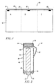
- FIG. 1 shows a presentation board digitizer system, generally designated 10, constructed and operative for use with the inventive drawing transmitter device.
- System 10 features a presentation board 12, which may be of any conventional type, provided with a plurality of receiver assemblies 14, 16, and 18.
- the receiver assemblies 14, 16, and 18 are preferably mounted in a strip 20 adapted for convenient attachment to presentation boards of different sizes and thicknesses. This attachment may be achieved through clamps or clips of any type (see, for example, commonly assigned U.S. Patent No. 6.067.080 (May 23, 2000) ( Retrofittable Apparatus For Converting A Substantially Planar Surface Into An Electronic Data Capture Device).
- Strip 20 also features a receiver 22.
- the present position of the movable element is derived from the time-of-flight (TOF) of signals from the movable element to the receiver assemblies by triangulation.
- An additional signal provides information such as, for example, the color of a pen being used.
- TOF time-of-flight
- system 10 employs more than one set of receivers.
- a first set of receivers is defined as the pair of receiver assemblies 14 and 16
- a second set of receivers is defined as the pair of receiver assemblies 16 and 18.
- the first set of receivers so defined is positioned for receiving a signal from the transmitter when the movable element is in a first region denoted A
- the second set of receivers is positioned for receiving the signal when the movable element is in a second region denoted C.
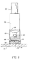
- FIGS 2-4 show a preferred embodiment of a transmitter device, generally designated 40, constructed and operative according to the invention, for use with a drawing implement 42 in a digitizer system.
- Transmitter device 40 may be used to advantage with a wide range of digitizer systems including, but not limited to, the presentation board digitizer systems described above.
- transmitter device 40 includes a housing 44 having a substantially cylindrical opening 46 which terminates at its lower end in an annular wedge surface 48 having a central bore 50.
- Drawing implement 42 is received within opening 46 with its operative tip 52 extending through bore 50.
- Transmitter device 40 also includes a retainer 54 in the form of a cover attachable to the upper end of opening 46 to retain drawing implement 42 in sition within housing 44.
- Retainer 54 features a spring element 56 for biasing drawing implement 42 towards annular wedge surface 48.
- a transmitter 58 is mounted on the lower surface of housing 44 proximal to bore 50.
- spring element 56 adjusts to any variations in length, and biases drawing implement 42 towards the lower end of housing 44 to ensure a correct position for use.
- This biasing in conjunction with the shape of annular wedge surface 48, serves to center the front end of a drawing implement of any size or shape.
- spring element 56 is preferably provided with a shaped abutment surface 60 having features for centering the back end of a drawing implement.
- abutment surface 60 has an axial conical projection as shown for centering drawing implements by engaging a rear axial recess which is common to almost all presentation board pens.
- abutment surface 60 maybe be formed with a conical recess or other features for centering the back of a drawing implement.
- FIG. 5A is a plot of the output of a contact switch activated by operational contact between a drawing implement and a presentation board as a function of time.
- FIG. 5A shows a drawing stroke period 100 for a continuous line segment, as well as individual stroke periods 102 for a dashed line.
- FIG. 5B illustrates the recorded drawing implement operation time profile produced by prior art systems corresponding to the contact profile of Figure 5A. It can be seen that for the continuous line segment (period 100), the effects of signal loss (shown by the dashed line) are not sufficient to interfere with tracking of the line. Thus, there is a small signal loss at the beginning of the period, but the majority of the stroke is recorded well. However, during period 102 the system response time is comparable to the length of the pen strokes. As a result, the dashed line is almost completely lost.
- the foregoing problem is solved by maintaining synchronization between the transmitter device 40 and the receiver system for a given period of time after the end of each pen stroke. This may be achieved, for example, by the use of electronic circuitry (not shown) that continues to operate the transmitter 58 for a given time interval after the microswitch 64 ceases to indicate a force exerted on the outer housing towards the operative tip of the drawing implement. False drawings signals are avoided by either disabling the transmitter 58 during the delay period, or by changing the content of the signal to indicate a non-contact pen state.
- the delay period is typically from about 1/2 second , and preferably between 1 and about 2 seconds, in duration.
- FIG. 5C illustrates the corresponding recorded drawing implement operation time profile produced by a presentation board digitizer system of Fig. 1.
- FIG. 5C shows the response profile of the transmitter device 40 as described. During an initial period of a single pen stroke, the response curve is similar to that shown on FIG. 5B. However, when short repeated strokes are encountered, the transmitter device 40 maintains synchronization between successive strokes, thereby providing an accurate response immediately on switching of the microswitch 64.
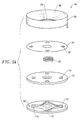
- FIG. 6 is a side cross sectional view of an eraser transmitter unit, constructed and operative for use with a digitizer system. While various multifunction writing implements have been identified above in connection with the prior art, it is thought that such devices are somewhat limited in their ability to operate in connection with various tracking schemes. Thus, some such implements are especially designed for optical schemes, while other implements are especially designed for electromagnetic tracking schemes.
- a major problem with eraser elements for use with digitizer systems is the common practice of employing only a part of the eraser surface. Because the digitizer is typically unable to distinguish between flat contact and edge contact of the eraser, the digitized image frequently shows a much greater erased area than has actually been cleared from the presentation board itself. To solve this problem, an eraser is constructed such that the eraser surface is self-orienting to lie parallel to the presentation board surface. This ensures that the contact area of the eraser element is always precisely defined.
- the implement shown on Fig. 6 may be used for several purposes.
- the implement includes a sleeve 182 that comprises a handle, and an eraser 188, which has a substantially flat, eraser surface 191.
- the eraser surface is preferably circular.
- the handle and eraser may be connected by a pivot joint 212, which may be a ball and socket having two degrees of rotational freedom.
- the pivot joint ensures that the eraser assumes an orientation with the eraser surface 191 parallel to the presentation board surface substantially independent of the orientation of the handle. Connection of the handle to the pivot joint is through a spring assembly 213.
- the implement also includes a transmitter similar to the transmitter 58 outer discussed above.
- a pressure sensing microswitch 190 is mounted to sense contact pressure between the handle and the eraser and operate the transmitter accordingly.
- the writing implement shown on Fig. 6 provides a sleeve 182 that has an inner diameter that is adapted to receive and securely retain a standard dry erase marker 180.
- the sleeve is tapered to follow the tapered contour of the pen and terminates with a switch 190 that detects movement of the pen tip, i.e. when the tip of the pen is placed to the writing surface. Such detection generates a signal that is communicated to the sensor array to indicate that the marking implement is now in contact with the writing surface (and not above the writing surface, as such detection would provide a false plane of information to the sensor array).
- the sensor array only tracks marking implement position when the marking implement is registered to the writing surface.
- Such signal may also communicate actual positional information, for example by providing a relay or feedback of tracking information received at the pen, such that a time based marking implement position may be derived.
- Such signal may also be modulated or digitally coded to identify a particular marking implement function or color, for example whether the marking implement is a red or blue pen, whether the marking implement is drawing a thin line or a thick line, or whether the marking implement is an eraser.
- the marking implement herein disclosed includes a collar 184 that is adapted to be securely fitted to the sleeve 182. The collar activates a switch 185 that indicates it is fitted to the sleeve. A plunger 186 is movably fitted within the collar. An eraser 188 is securely received within the plunger.
- the eraser In operation, the eraser is pressed to the writing surface to erase marking thereon. This action pushes the plunger into the collar, thereby activating the switch 190, and thereby indicating contact of the eraser with the writing surface. The presence of the collar operates the switch 185, thereby indicating that the marking implement is performing an eraser function.
- the invention is readily adapted for use with any modern locating technique, including any of those techniques discussed above in connection with the prior art.
Landscapes
- Engineering & Computer Science (AREA)
- General Engineering & Computer Science (AREA)
- Theoretical Computer Science (AREA)
- Physics & Mathematics (AREA)
- Human Computer Interaction (AREA)
- General Physics & Mathematics (AREA)
- Mechanical Engineering (AREA)
- Acoustics & Sound (AREA)
- Position Input By Displaying (AREA)
- Road Signs Or Road Markings (AREA)
- Push-Button Switches (AREA)
- Measurement Of Velocity Or Position Using Acoustic Or Ultrasonic Waves (AREA)
Claims (5)
- Dispositif de transmission de dessin à utiliser avec un système (10) pour numériser des trajets opérationnels d'un outil de dessin portable (42), l'outil de dessin (42) ayant un corps et une pointe active (52), le dispositif de transmission de dessin (40) comprenant :un émetteur (58);un boítier (44) ayant une ouverture substantiellement cylindrique (46) aboutissant à une première extrémité dans une surface de calage annulaire (48) avec un trou central (50), ledit boítier (44) recevant une partie du corps de l'outil de dessin (42) avec sa pointe active (52) dépassant dudit trou central (50) ; etun dispositif de retenue (54) pouvant être fixé à une deuxième extrémité de ladite ouverture pour retenir ledit outil de dessin (42) à l'intérieur du boítier (44), ledit dispositif de retenue (54) ayant un élément à ressort (56) pour orienter ledit outil de dessin (42) vers ladite surface de calage annulaire (48).
- Dispositif selon la revendication 1, dans lequel ledit émetteur (58) est monté sur une surface inférieure dudit boítier à proximité dudit trou central (50).
- Dispositif selon la revendication 2, dans lequel ledit boítier comprend en outre :un microcontact (64) actionné par des changements en pression exercée sur ladite surface de calage annulaire (48) afin de réagir à une force exercée sur la pointe active de l'outil de dessin (42) vers ledit boítier (44) ; etdes circuits électroniques réagissant audit microcontact (64) pour modifier le fonctionnement dudit émetteur (58) au moins lorsque ledit microcontact (64) indique une force exercée sur la pointe active (52) de l'outil de dessin (42) vers ledit boítier (44).
- Dispositif selon la revendication 3, dans lequel ledit émetteur (58) est un transducteur.
- Dispositif selon la revendication 4, comprenant en outre :des éléments d'une liaison de communication électromagnétique (58), lesdits éléments étant associés auxdits circuits électroniques.
Applications Claiming Priority (3)
| Application Number | Priority Date | Filing Date | Title |
|---|---|---|---|
| US808524 | 1985-12-13 | ||
| US08/808,524 US5866856A (en) | 1997-02-28 | 1997-02-28 | Marking device for electronic presentation board |
| PCT/US1998/003883 WO1998038595A1 (fr) | 1997-02-28 | 1998-02-26 | Dispositif de marquage pour tableau de presentation electronique |
Publications (2)
| Publication Number | Publication Date |
|---|---|
| EP0961989A1 EP0961989A1 (fr) | 1999-12-08 |
| EP0961989B1 true EP0961989B1 (fr) | 2003-05-14 |
Family
ID=25199028
Family Applications (1)
| Application Number | Title | Priority Date | Filing Date |
|---|---|---|---|
| EP98910102A Expired - Lifetime EP0961989B1 (fr) | 1997-02-28 | 1998-02-26 | Dispositif de marquage pour tableau de presentation electronique |
Country Status (11)
| Country | Link |
|---|---|
| US (1) | US5866856A (fr) |
| EP (1) | EP0961989B1 (fr) |
| JP (1) | JP2000510274A (fr) |
| AT (1) | ATE240562T1 (fr) |
| AU (1) | AU726389B2 (fr) |
| BR (1) | BR9807868A (fr) |
| CA (1) | CA2281717A1 (fr) |
| DE (1) | DE69814596T2 (fr) |
| IL (1) | IL131374A (fr) |
| NZ (1) | NZ337287A (fr) |
| WO (1) | WO1998038595A1 (fr) |
Families Citing this family (43)
| Publication number | Priority date | Publication date | Assignee | Title |
|---|---|---|---|---|
| US6218964B1 (en) * | 1996-09-25 | 2001-04-17 | Christ G. Ellis | Mechanical and digital reading pen |
| US6067080A (en) * | 1997-02-21 | 2000-05-23 | Electronics For Imaging | Retrofittable apparatus for converting a substantially planar surface into an electronic data capture device |
| US6326565B1 (en) | 1997-02-28 | 2001-12-04 | Electronics For Imaging, Inc. | Marking device for electronic presentation board |
| US6292177B1 (en) | 1997-03-05 | 2001-09-18 | Tidenet, Inc. | Marking device for electronic presentation board |
| IL120417A (en) * | 1997-03-10 | 2000-09-28 | Electronics For Imaging Inc | Presentation board digitizer systems |
| US6265676B1 (en) * | 1997-03-10 | 2001-07-24 | Electronics For Imaging, Inc. | Systems and processing algorithms for ultrasound time-of-flight digitizer systems |
| US6442213B1 (en) * | 1997-04-22 | 2002-08-27 | Silicon Laboratories Inc. | Digital isolation system with hybrid circuit in ADC calibration loop |
| US6104387A (en) * | 1997-05-14 | 2000-08-15 | Virtual Ink Corporation | Transcription system |
| US6204457B1 (en) * | 1997-06-20 | 2001-03-20 | Fine Point Innovations, Inc. | Electromagnetic inking digitizer pen and method |
| US6232962B1 (en) * | 1998-05-14 | 2001-05-15 | Virtual Ink Corporation | Detector assembly for use in a transcription system |
| US6373003B1 (en) * | 1998-10-13 | 2002-04-16 | Electronics For Imaging, Inc. | Marking device for electronic presentation board |
| US6414673B1 (en) | 1998-11-10 | 2002-07-02 | Tidenet, Inc. | Transmitter pen location system |
| USD443300S1 (en) | 1999-05-17 | 2001-06-05 | Ideo Product Development Inc. | Stylus pen assembly |
| US7721948B1 (en) * | 1999-05-25 | 2010-05-25 | Silverbrook Research Pty Ltd | Method and system for online payments |
| US20070233513A1 (en) * | 1999-05-25 | 2007-10-04 | Silverbrook Research Pty Ltd | Method of providing merchant resource or merchant hyperlink to a user |
| US7102772B1 (en) * | 1999-05-25 | 2006-09-05 | Silverbrook Research Pty Ltd | Method and system for delivery of a facsimile |
| US7857201B2 (en) * | 1999-05-25 | 2010-12-28 | Silverbrook Research Pty Ltd | Method and system for selection |
| US7593899B1 (en) | 1999-05-25 | 2009-09-22 | Silverbrook Research Pty Ltd | Method and system for online payments |
| US7760969B2 (en) * | 1999-05-25 | 2010-07-20 | Silverbrook Research Pty Ltd | Method of providing information via context searching from a printed substrate |
| US20070143715A1 (en) * | 1999-05-25 | 2007-06-21 | Silverbrook Research Pty Ltd | Method of providing information via printed substrate and gesture recognition |
| US7762453B2 (en) * | 1999-05-25 | 2010-07-27 | Silverbrook Research Pty Ltd | Method of providing information via a printed substrate with every interaction |
| US7971784B2 (en) * | 1999-05-25 | 2011-07-05 | Silverbrook Research Pty Ltd | Sensing device with mode changes via nib switch |
| US8113950B2 (en) | 1999-05-25 | 2012-02-14 | Silverbrook Research Pty Ltd | Competition entry with limited return messaging |
| US7793824B2 (en) * | 1999-05-25 | 2010-09-14 | Silverbrook Research Pty Ltd | System for enabling access to information |
| US7832626B2 (en) * | 1999-05-25 | 2010-11-16 | Silverbrook Research Pty Ltd | Anonymous competition entry |
| GB2353501A (en) * | 1999-08-26 | 2001-02-28 | John Heppell | Computerised system for recording movements of a marker pen on a whiteboard |
| USD461499S1 (en) | 1999-10-22 | 2002-08-13 | Ideo Product Development, Inc. | Combination stylus and pen |
| US6657618B2 (en) | 2001-01-23 | 2003-12-02 | Eloise Gatewood-Moore | Optical memory unit for capturing complete analog motion |
| USD458635S1 (en) | 2001-08-22 | 2002-06-11 | Ideo Product Development, Inc. | Combination stylus and pen |
| NZ535953A (en) | 2002-04-15 | 2007-02-23 | Epos Technologies Ltd | Method and system for obtaining positioning data |
| US6875933B2 (en) | 2002-05-10 | 2005-04-05 | Luidia Inc. | Methods and apparatus for configuring a writing surface |
| US7525050B1 (en) | 2004-04-23 | 2009-04-28 | Luidia, Inc. | Interference removal in pointing device locating systems |
| JP5243025B2 (ja) | 2004-05-17 | 2013-07-24 | エポス ディベロップメント リミテッド | 音響測位システムのための頑健な音響同期シグナリング |
| US8391959B2 (en) * | 2004-09-29 | 2013-03-05 | Tel Hashomer Medical Research Infrastructure And Services Ltd. | Composition for improving efficiency of drug delivery |
| US7367944B2 (en) | 2004-12-13 | 2008-05-06 | Tel Hashomer Medical Research Infrastructure And Services Ltd. | Method and system for monitoring ablation of tissues |
| US20060130966A1 (en) * | 2004-12-20 | 2006-06-22 | Darko Babic | Method and system for flowing a supercritical fluid in a high pressure processing system |
| CN101180601B (zh) * | 2005-03-23 | 2014-09-17 | 高通股份有限公司 | 数字笔和数字笔系统 |
| TWI301590B (en) * | 2005-12-30 | 2008-10-01 | Ibm | Handwriting input method, apparatus, system and computer recording medium with a program recorded thereon of capturing video data of real-time handwriting strokes for recognition |
| AU2008224542B2 (en) * | 2007-03-14 | 2012-01-19 | Qualcomm Incorporated | MEMS microphone |
| US20090009490A1 (en) * | 2007-07-05 | 2009-01-08 | Shih-Chin Yang | Ultrasonic input device for information display |
| US9181555B2 (en) * | 2007-07-23 | 2015-11-10 | Ramot At Tel-Aviv University Ltd. | Photocatalytic hydrogen production and polypeptides capable of same |
| US8243028B2 (en) * | 2008-06-13 | 2012-08-14 | Polyvision Corporation | Eraser assemblies and methods of manufacturing same |
| US11169611B2 (en) * | 2012-03-26 | 2021-11-09 | Apple Inc. | Enhanced virtual touchpad |
Family Cites Families (17)
| Publication number | Priority date | Publication date | Assignee | Title |
|---|---|---|---|---|
| US3613066A (en) * | 1968-10-22 | 1971-10-12 | Cii | Computer input equipment |
| JPS59107297U (ja) * | 1983-01-08 | 1984-07-19 | 富士通株式会社 | 電子黒板用消去器 |
| US4570033A (en) * | 1983-09-09 | 1986-02-11 | Numonics Corporation | Polyphase digitizer |
| US4552991A (en) * | 1983-11-03 | 1985-11-12 | Numonics Corporation | Absolute position coordinate determining device employing a single phase difference measurement to determine cursor position |
| US4654648A (en) * | 1984-12-17 | 1987-03-31 | Herrington Richard A | Wireless cursor control system |
| EP0229637A3 (fr) * | 1986-01-09 | 1988-10-05 | Wacom Co., Ltd. | Appareil de tableau électronique |
| US4777329A (en) * | 1987-08-24 | 1988-10-11 | Microfield Graphics, Inc. | Graphic input system |
| US4814552A (en) * | 1987-12-02 | 1989-03-21 | Xerox Corporation | Ultrasound position input device |
| US4853715A (en) * | 1988-06-17 | 1989-08-01 | Numonics Corporation | Plotter head control device |
| JPH01320521A (ja) * | 1988-06-22 | 1989-12-26 | Wacom Co Ltd | 電子黒板装置及びその筆記具等 |
| US4963703A (en) * | 1989-07-18 | 1990-10-16 | Numonics Corporation | Coordinate determining device using spatial filters |
| CA2058219C (fr) * | 1991-10-21 | 2002-04-02 | Smart Technologies Inc. | Systeme d'affichage interactif |
| US5380959A (en) * | 1992-06-15 | 1995-01-10 | Carroll Touch, Inc. | Controller for an acoustic touch panel |
| US5308936A (en) * | 1992-08-26 | 1994-05-03 | Mark S. Knighton | Ultrasonic pen-type data input device |
| US5248856A (en) * | 1992-10-07 | 1993-09-28 | Microfield Graphics, Inc. | Code-based, electromagnetic-field-responsive graphic data-acquisition system |
| WO1995011500A1 (fr) * | 1993-10-18 | 1995-04-27 | Summagraphics Corporation | Stylet sensible a la pression ayant un element pointe elastiquement compressible |
| US5434370A (en) * | 1993-11-05 | 1995-07-18 | Microfield Graphics, Inc. | Marking system with pen-up/pen-down tracking |
-
1997
- 1997-02-28 US US08/808,524 patent/US5866856A/en not_active Expired - Lifetime
-
1998
- 1998-02-26 AT AT98910102T patent/ATE240562T1/de not_active IP Right Cessation
- 1998-02-26 IL IL13137498A patent/IL131374A/xx not_active IP Right Cessation
- 1998-02-26 CA CA002281717A patent/CA2281717A1/fr not_active Abandoned
- 1998-02-26 BR BR9807868-2A patent/BR9807868A/pt not_active IP Right Cessation
- 1998-02-26 AU AU64430/98A patent/AU726389B2/en not_active Ceased
- 1998-02-26 JP JP10537904A patent/JP2000510274A/ja active Pending
- 1998-02-26 DE DE69814596T patent/DE69814596T2/de not_active Expired - Lifetime
- 1998-02-26 WO PCT/US1998/003883 patent/WO1998038595A1/fr not_active Ceased
- 1998-02-26 EP EP98910102A patent/EP0961989B1/fr not_active Expired - Lifetime
- 1998-02-26 NZ NZ337287A patent/NZ337287A/en unknown
Also Published As
| Publication number | Publication date |
|---|---|
| DE69814596D1 (de) | 2003-06-18 |
| AU6443098A (en) | 1998-09-18 |
| CA2281717A1 (fr) | 1998-09-03 |
| US5866856A (en) | 1999-02-02 |
| WO1998038595A1 (fr) | 1998-09-03 |
| EP0961989A1 (fr) | 1999-12-08 |
| AU726389B2 (en) | 2000-11-09 |
| NZ337287A (en) | 2001-06-29 |
| IL131374A (en) | 2003-06-24 |
| DE69814596T2 (de) | 2004-03-25 |
| JP2000510274A (ja) | 2000-08-08 |
| BR9807868A (pt) | 2000-02-22 |
| ATE240562T1 (de) | 2003-05-15 |
| IL131374A0 (en) | 2001-01-28 |
Similar Documents
| Publication | Publication Date | Title |
|---|---|---|
| EP0961989B1 (fr) | Dispositif de marquage pour tableau de presentation electronique | |
| CA2371960C (fr) | Numeriseur pour tableaux de conference | |
| AU726304B2 (en) | Marking device for electronic presentation board | |
| AU718113C (en) | Presentation board digitizer systems | |
| US6326565B1 (en) | Marking device for electronic presentation board | |
| US6373003B1 (en) | Marking device for electronic presentation board | |
| IL153694A (en) | Marking device for electronic presentation board | |
| NZ502507A (en) | Eraser for electronic presentation board, handle pivots so that eraser remains flat on board | |
| AU755920B2 (en) | Marking device for electronic presentation board | |
| NZ502385A (en) | Ultrasound transmitter for presentation board digitiser systems |
Legal Events
| Date | Code | Title | Description |
|---|---|---|---|
| PUAI | Public reference made under article 153(3) epc to a published international application that has entered the european phase |
Free format text: ORIGINAL CODE: 0009012 |
|
| 17P | Request for examination filed |
Effective date: 19990817 |
|
| AK | Designated contracting states |
Kind code of ref document: A1 Designated state(s): AT BE CH DE DK ES FI FR GB GR IE IT LI LU MC NL PT SE |
|
| RAP1 | Party data changed (applicant data changed or rights of an application transferred) |
Owner name: ELECTRONICS FOR IMAGING |
|
| 111L | Licence recorded |
Free format text: 19991215 0100 PEGASUS TECHNOLOGIES, LTD |
|
| 17Q | First examination report despatched |
Effective date: 20001114 |
|
| GRAH | Despatch of communication of intention to grant a patent |
Free format text: ORIGINAL CODE: EPIDOS IGRA |
|
| GRAH | Despatch of communication of intention to grant a patent |
Free format text: ORIGINAL CODE: EPIDOS IGRA |
|
| GRAA | (expected) grant |
Free format text: ORIGINAL CODE: 0009210 |
|
| AK | Designated contracting states |
Designated state(s): AT BE CH DE DK ES FI FR GB GR IE IT LI LU MC NL PT SE |
|
| PG25 | Lapsed in a contracting state [announced via postgrant information from national office to epo] |
Ref country code: LI Free format text: LAPSE BECAUSE OF FAILURE TO SUBMIT A TRANSLATION OF THE DESCRIPTION OR TO PAY THE FEE WITHIN THE PRESCRIBED TIME-LIMIT Effective date: 20030514 Ref country code: IT Free format text: LAPSE BECAUSE OF FAILURE TO SUBMIT A TRANSLATION OF THE DESCRIPTION OR TO PAY THE FEE WITHIN THE PRESCRIBED TIME-LIMIT;WARNING: LAPSES OF ITALIAN PATENTS WITH EFFECTIVE DATE BEFORE 2007 MAY HAVE OCCURRED AT ANY TIME BEFORE 2007. THE CORRECT EFFECTIVE DATE MAY BE DIFFERENT FROM THE ONE RECORDED. Effective date: 20030514 Ref country code: FI Free format text: LAPSE BECAUSE OF FAILURE TO SUBMIT A TRANSLATION OF THE DESCRIPTION OR TO PAY THE FEE WITHIN THE PRESCRIBED TIME-LIMIT Effective date: 20030514 Ref country code: CH Free format text: LAPSE BECAUSE OF FAILURE TO SUBMIT A TRANSLATION OF THE DESCRIPTION OR TO PAY THE FEE WITHIN THE PRESCRIBED TIME-LIMIT Effective date: 20030514 Ref country code: BE Free format text: LAPSE BECAUSE OF FAILURE TO SUBMIT A TRANSLATION OF THE DESCRIPTION OR TO PAY THE FEE WITHIN THE PRESCRIBED TIME-LIMIT Effective date: 20030514 Ref country code: AT Free format text: LAPSE BECAUSE OF FAILURE TO SUBMIT A TRANSLATION OF THE DESCRIPTION OR TO PAY THE FEE WITHIN THE PRESCRIBED TIME-LIMIT Effective date: 20030514 |
|
| REG | Reference to a national code |
Ref country code: GB Ref legal event code: FG4D |
|
| REG | Reference to a national code |
Ref country code: CH Ref legal event code: EP |
|
| REG | Reference to a national code |
Ref country code: IE Ref legal event code: FG4D |
|
| REF | Corresponds to: |
Ref document number: 69814596 Country of ref document: DE Date of ref document: 20030618 Kind code of ref document: P |
|
| PG25 | Lapsed in a contracting state [announced via postgrant information from national office to epo] |
Ref country code: SE Free format text: LAPSE BECAUSE OF FAILURE TO SUBMIT A TRANSLATION OF THE DESCRIPTION OR TO PAY THE FEE WITHIN THE PRESCRIBED TIME-LIMIT Effective date: 20030814 Ref country code: PT Free format text: LAPSE BECAUSE OF FAILURE TO SUBMIT A TRANSLATION OF THE DESCRIPTION OR TO PAY THE FEE WITHIN THE PRESCRIBED TIME-LIMIT Effective date: 20030814 Ref country code: GR Free format text: LAPSE BECAUSE OF FAILURE TO SUBMIT A TRANSLATION OF THE DESCRIPTION OR TO PAY THE FEE WITHIN THE PRESCRIBED TIME-LIMIT Effective date: 20030814 Ref country code: DK Free format text: LAPSE BECAUSE OF FAILURE TO SUBMIT A TRANSLATION OF THE DESCRIPTION OR TO PAY THE FEE WITHIN THE PRESCRIBED TIME-LIMIT Effective date: 20030814 |
|
| PG25 | Lapsed in a contracting state [announced via postgrant information from national office to epo] |
Ref country code: ES Free format text: LAPSE BECAUSE OF FAILURE TO SUBMIT A TRANSLATION OF THE DESCRIPTION OR TO PAY THE FEE WITHIN THE PRESCRIBED TIME-LIMIT Effective date: 20030825 |
|
| REG | Reference to a national code |
Ref country code: CH Ref legal event code: PL |
|
| ET | Fr: translation filed | ||
| PG25 | Lapsed in a contracting state [announced via postgrant information from national office to epo] |
Ref country code: LU Free format text: LAPSE BECAUSE OF NON-PAYMENT OF DUE FEES Effective date: 20040226 Ref country code: IE Free format text: LAPSE BECAUSE OF NON-PAYMENT OF DUE FEES Effective date: 20040226 |
|
| PG25 | Lapsed in a contracting state [announced via postgrant information from national office to epo] |
Ref country code: MC Free format text: LAPSE BECAUSE OF NON-PAYMENT OF DUE FEES Effective date: 20040228 |
|
| PLBE | No opposition filed within time limit |
Free format text: ORIGINAL CODE: 0009261 |
|
| 26N | No opposition filed |
Effective date: 20040217 |
|
| PG25 | Lapsed in a contracting state [announced via postgrant information from national office to epo] |
Ref country code: NL Free format text: LAPSE BECAUSE OF NON-PAYMENT OF DUE FEES Effective date: 20040901 |
|
| NLV4 | Nl: lapsed or anulled due to non-payment of the annual fee |
Effective date: 20040901 |
|
| REG | Reference to a national code |
Ref country code: IE Ref legal event code: MM4A |
|
| RAP2 | Party data changed (patent owner data changed or rights of a patent transferred) |
Owner name: ELECTRONICS FOR IMAGING, INC. |
|
| REG | Reference to a national code |
Ref country code: GB Ref legal event code: 732E |
|
| REG | Reference to a national code |
Ref country code: FR Ref legal event code: TP |
|
| REG | Reference to a national code |
Ref country code: FR Ref legal event code: PLFP Year of fee payment: 19 |
|
| REG | Reference to a national code |
Ref country code: FR Ref legal event code: PLFP Year of fee payment: 20 |
|
| PGFP | Annual fee paid to national office [announced via postgrant information from national office to epo] |
Ref country code: DE Payment date: 20170221 Year of fee payment: 20 Ref country code: FR Payment date: 20170112 Year of fee payment: 20 |
|
| PGFP | Annual fee paid to national office [announced via postgrant information from national office to epo] |
Ref country code: GB Payment date: 20170222 Year of fee payment: 20 |
|
| REG | Reference to a national code |
Ref country code: DE Ref legal event code: R071 Ref document number: 69814596 Country of ref document: DE |
|
| REG | Reference to a national code |
Ref country code: GB Ref legal event code: PE20 Expiry date: 20180225 |
|
| PG25 | Lapsed in a contracting state [announced via postgrant information from national office to epo] |
Ref country code: GB Free format text: LAPSE BECAUSE OF EXPIRATION OF PROTECTION Effective date: 20180225 |