EP0963031A2 - Verfahren und Einziehwerkzeugteil zum Herstellen eines Stators für elektrische Maschinen - Google Patents
Verfahren und Einziehwerkzeugteil zum Herstellen eines Stators für elektrische Maschinen Download PDFInfo
- Publication number
- EP0963031A2 EP0963031A2 EP99110603A EP99110603A EP0963031A2 EP 0963031 A2 EP0963031 A2 EP 0963031A2 EP 99110603 A EP99110603 A EP 99110603A EP 99110603 A EP99110603 A EP 99110603A EP 0963031 A2 EP0963031 A2 EP 0963031A2
- Authority
- EP
- European Patent Office
- Prior art keywords
- coils
- wire ends
- stator
- drawn
- laminated core
- Prior art date
- Legal status (The legal status is an assumption and is not a legal conclusion. Google has not performed a legal analysis and makes no representation as to the accuracy of the status listed.)
- Withdrawn
Links
Images



Classifications
-
- H—ELECTRICITY
- H02—GENERATION; CONVERSION OR DISTRIBUTION OF ELECTRIC POWER
- H02K—DYNAMO-ELECTRIC MACHINES
- H02K15/00—Processes or apparatus specially adapted for manufacturing, assembling, maintaining or repairing of dynamo-electric machines
- H02K15/06—Embedding prefabricated windings in the machines
- H02K15/062—Windings in slots; Salient pole windings
- H02K15/065—Windings consisting of complete sections, e.g. coils or waves
- H02K15/067—Windings consisting of complete sections, e.g. coils or waves inserted in parallel to the axis of the slots or inter-polar channels
- H02K15/068—Strippers; Embedding windings by strippers
-
- H—ELECTRICITY
- H02—GENERATION; CONVERSION OR DISTRIBUTION OF ELECTRIC POWER
- H02K—DYNAMO-ELECTRIC MACHINES
- H02K15/00—Processes or apparatus specially adapted for manufacturing, assembling, maintaining or repairing of dynamo-electric machines
- H02K15/30—Manufacture of winding connections
-
- Y—GENERAL TAGGING OF NEW TECHNOLOGICAL DEVELOPMENTS; GENERAL TAGGING OF CROSS-SECTIONAL TECHNOLOGIES SPANNING OVER SEVERAL SECTIONS OF THE IPC; TECHNICAL SUBJECTS COVERED BY FORMER USPC CROSS-REFERENCE ART COLLECTIONS [XRACs] AND DIGESTS
- Y10—TECHNICAL SUBJECTS COVERED BY FORMER USPC
- Y10T—TECHNICAL SUBJECTS COVERED BY FORMER US CLASSIFICATION
- Y10T29/00—Metal working
- Y10T29/49—Method of mechanical manufacture
- Y10T29/49002—Electrical device making
- Y10T29/49009—Dynamoelectric machine
-
- Y—GENERAL TAGGING OF NEW TECHNOLOGICAL DEVELOPMENTS; GENERAL TAGGING OF CROSS-SECTIONAL TECHNOLOGIES SPANNING OVER SEVERAL SECTIONS OF THE IPC; TECHNICAL SUBJECTS COVERED BY FORMER USPC CROSS-REFERENCE ART COLLECTIONS [XRACs] AND DIGESTS
- Y10—TECHNICAL SUBJECTS COVERED BY FORMER USPC
- Y10T—TECHNICAL SUBJECTS COVERED BY FORMER US CLASSIFICATION
- Y10T29/00—Metal working
- Y10T29/53—Means to assemble or disassemble
- Y10T29/5313—Means to assemble electrical device
- Y10T29/53143—Motor or generator
-
- Y—GENERAL TAGGING OF NEW TECHNOLOGICAL DEVELOPMENTS; GENERAL TAGGING OF CROSS-SECTIONAL TECHNOLOGIES SPANNING OVER SEVERAL SECTIONS OF THE IPC; TECHNICAL SUBJECTS COVERED BY FORMER USPC CROSS-REFERENCE ART COLLECTIONS [XRACs] AND DIGESTS
- Y10—TECHNICAL SUBJECTS COVERED BY FORMER USPC
- Y10T—TECHNICAL SUBJECTS COVERED BY FORMER US CLASSIFICATION
- Y10T29/00—Metal working
- Y10T29/53—Means to assemble or disassemble
- Y10T29/5313—Means to assemble electrical device
- Y10T29/53143—Motor or generator
- Y10T29/53161—Motor or generator including deforming means
Definitions
- the invention relates to a method for producing a Stators for electrical machines in which a variety pre-wound by coils and drawn into a stator laminated core and before pulling in the wire ends of the coils temporarily in a certain, pre-aligned position with a holder member separate from the stator laminated core connected and relative after pulling in a predetermined position for the stator laminated core.
- the invention has for its object a method and a pull-in tool part suitable for its implementation with the help of which the wire ends of the coils, independently whether they are stripped from the winding template into a transfer or insertion tool, more reliably and interconnected faster than before and to the intended terminals or auxiliary terminals can.
- the above object is achieved in that the wire ends of the coils connected to the holding member during the drawing-in remain and mechanically after retraction from the holding member solved and in the predetermined, relative to the stator core specified location to be transferred.
- the invention has the advantage that it is proportionate is simple, in the continuously progressing manufacturing process the wire ends each directly related with winding a coil or group of coils in a particular one Position temporarily with a separate holding device to connect and while pulling the coils in to keep the stator laminated core in connection.
- This suggestion is based on the consideration that at the end of each winding process the wire ends still have a defined position. You should therefore not let go of it after the Laboriously catching the pull-in process again, but over it the pulling-in process and any molding operation that may have been carried out keep orderly to form the winding heads. requirement for this is only the additional mentioned Holding device with which the wire ends during the pulling process and possibly remain connected to the molding operation. Therefore however, z. B.
- stator laminated core after pulling in the coils to turn, so that now the disc-shaped Holding organ forming support plate above the Stator laminated core is located and can be lifted off, and mechanically grasp the wire ends before or after lifting and into those defined by terminals or auxiliary terminals Layer to transfer or interconnect.
- the new method can also be used without turning the stator core To run.
- the coils are used together or separately for continuity checked while the wire ends are still in the pre-aligned position, e.g. before or during of moving in and / or after this process.
- the invention thus offers the possibility of wire or insulation faults on the coils at an early stage of manufacture to discover and thereby save costs.
- Retractable tool part takes in conventional Interpose coil turns wound on a template ring-shaped, parallel slats on and can be coupled with a pull-in device through which the Coils from the fins in the grooves of a stator core are strippable, but has a special feature Support plate for the coils on their outer circumference Holding devices with electrical contact options can be provided for releasable connection with are attached to the wire ends of the coils.
- FIG. 1 illustrates the problem that after the conventional pulling in of pre-wound coils 10, which are shown here in simplified form, in a stator laminated core 12 at least if there are a lot of coils or coil groups are very difficult, in As part of an automatic production, the wire ends 14 of the To take coils and according to FIG. 5 each on very specific To define terminals or auxiliary terminals or for identify an interconnection.
- FIGs 2 to 5 are stages of a new process shown. This is where the first process steps begin immediately after winding a spool 10.
- the coil turns during and / or after winding the wire on a not shown stencil stripped down from this, whereby between the ring-shaped parallel rods or lamellae 24 of a drawing-in tool part designated overall by 26 fall.
- This drawing tool part can a so-called pull-in tool part that after the recording of the coils 10 with the lower part of a drawing tool Puller connected and then to pull the Coils 10 in a stator laminated core placed on the fins 24 is used.
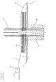
- the embodiment of Fig. 2 shows such a complete pull-in tool upper part 26 with a so-called. Star 28, which after coupling with the rest of the retractor axially along the slats 24 is advanced, taking the coils 10 with it and pulls into the grooves of the stator core.
- a drawing tool part shown in Fig. 2A could be used 26 'also a simple annular arrangement of parallel Bars 24 'that are on a slightly larger radius than the slats 24 of the upper part of the drawing tool are arranged and connected to a plate 34 'perforated in the middle are.
- the simple transfer and retracting tool part mentioned 2A can be connected to the rods 24 ' Base plate 34 'on which the pre-wound coils 10 'during the transfer from the winding device to the drawing device lying on, also with holding devices 32 be provided and thus the organ for temporary holding the wire ends 14 form.
- the holding devices 32 can take the form of metallic or rubbery Pinch points or possibly only of labyrinthine Have recesses in the edge of the plate 34 or 34 '.
- the pull-in star 28 is started up, has the Coils 10 taken along and drawn into a stator laminated core, and was then withdrawn again. While the pulling process is due to the clamped wire ends or an auxiliary gripper, the plate 34 has also been lifted. It is understood that in individual cases the length of the wire ends 14 can also be chosen so large that during the Retracting the plate 34 is not raised with. she can also be smuggled through a subsequent molding process become.
- the stator laminated core is not necessarily together with the retracted coils and the plate 34 turned upside down.
- the turning device is denoted by 36 in FIG.
- the plate 34 is now above the stator core.
- the wire ends 14, each by the holding devices 32 in a particular Position held by a gripper, not shown detected and according to Fig. 4 with a terminal or auxiliary terminal 38, the z. B. on the stator core or on one of these supporting pallet is attached.
- the platen 34 again on an empty Transfer and pull-in tool part 26 are placed, and then the one described with reference to FIGS. 2 to 4 is repeated Process.
- the one up to the connection of the wire ends 38 with electrical terminals or auxiliary terminals The stator is shown in FIG. 5.
Landscapes
- Engineering & Computer Science (AREA)
- Manufacturing & Machinery (AREA)
- Power Engineering (AREA)
- Manufacture Of Motors, Generators (AREA)
Abstract
Description
- Fig. 1
- eine vereinfachte Draufsicht auf ein Statorblechpaket nach dem herkömmlichen Einziehen einer Vielzahl von Spulen vor dem Ordnen und Festlegen der Drahtenden;
- Fig. 2
- einen Axialschnitt durch ein unter einer nicht gezeigten Schablone positioniertes Einziehwerkzeugteil nach der Aufnahme vorgewickelter Spulen im axialen Längsschnitt;
- Fig. 2A
- ein weiteres Ausführungsbeispiel eines Einziehwerkzeugteils;
- Fig. 2B
- das Einziehwerkzeugteil nach Fig. 2A nach dem Aufsetzen auf eine Einziehvorrichtung;
- Fig. 3
- das Einziehwerkzeugteil nach Fig. 2 nach dem Einziehen der Spulen in ein Statorblechpaket sowie dessen Wenden;
- Fig. 4
- das gemäß Fig. 3 gewendete Statorblechpaket in der Phase des Anschlagens der Drahtenden an Hilfsterminals;
- Fig. 5
- eine Draufsicht auf einen Stator, bei dem sämtliche Drahtenden der Spulen an Hilfsterminals festgelegt sind.
Claims (5)
- Verfahren zum Herstellen eines Stators für elektrische Maschinen, bei dem eine Vielzahl von Spulen (10) vorgewickelt und in ein Statorblechpaket (12) eingezogen wird und vor dem Einziehen die Drahtenden (14) der Spulen (10) in einer bestimmten, vor-ausgerichteten Stellung vorübergehend mit einem vom Statorblechpaket getrennten Halterorgan (32, 34, 34') verbunden und nach dem Einziehen in vorbestimmter Lage relativ zum Statorblechpaket festgelegt werden, dadurch gekennzeichnet, daß die Drahtenden (14) der Spulen (10) während des Einziehens mit dem Halteorgan (32, 34, 34') verbunden bleiben und nach dem Einziehen maschinell vom Halteorgan (32, 34, 34') gelöst und in die vorbestimmte, relativ zum Statorblechpaket festgelegte Lage überführt werden.
- Verfahren nach Anspruch 1, dadurch gekennzeichnet, daß die Spulen (10) beim oder nach dem Wickeln auf ein Einziehwerkzeugteil (26, 26') mit ringförmig angeordneten, parallelen Lamellen (24) oder Stäben (24') und einer Auflageplatte (34, 34') für die Spulen (10) übertragen werden, welche das Halteorgan (32, 34, 34') bildet, mit dem die Drahtenden (14) vorübergehend verbunden werden.
- Verfahren nach Anspruch 2, dadurch gekennzeichnet, daß nach dem Einziehen der Spulen (10) das Statorblechpaket (12) gewendet, die Auflageplatte (34, 34') nach oben abgehoben und die Drahtenden (14) vor oder nach dem Abheben maschinell erfaßt und in die festgelegte Lage überführt werden.
- Verfahren nach Anspruch 1, dadurch gekennzeichnet, daß die Spulen (10) auf Stromdurchgang geprüft werden, während sich die Drahtenden (14) in der vor-ausgerichteten Stellung befinden.
- Einziehwerkzeugteil zur Durchführung des Verfahrens nach Anspruch 1, welches auf einer Schablone gewickelte Spulen (10) zwischen ringförmig angeordneten, parallelen Lamellen (24) oder Stäben (24') aufnimmt und mit einer Einziehvorrichtung kuppelbar ist, durch die die Spulen (10) von den Lamellen (24) bzw. Stäben (24') in die Nuten eines Statorblechpakets (12) abstreifbar sind, dadurch gekennzeichnet, daß es eine Auflageplatte (34, 34') für die Spulen aufweist, an deren äußerem Umfang Halteeinrichtungen (32) zur lösbaren Verbindung mit den Drahtenden (14) der Spulen (10) angebracht sind.
Applications Claiming Priority (2)
| Application Number | Priority Date | Filing Date | Title |
|---|---|---|---|
| DE19824920A DE19824920A1 (de) | 1998-06-04 | 1998-06-04 | Verfahren zum Herstellen eines Stators für elektrische Maschinen und Einziehwerkzeugteil zur Durchführung des Verfahrens |
| DE19824920 | 1998-06-04 |
Publications (2)
| Publication Number | Publication Date |
|---|---|
| EP0963031A2 true EP0963031A2 (de) | 1999-12-08 |
| EP0963031A3 EP0963031A3 (de) | 2002-05-02 |
Family
ID=7869854
Family Applications (1)
| Application Number | Title | Priority Date | Filing Date |
|---|---|---|---|
| EP99110603A Withdrawn EP0963031A3 (de) | 1998-06-04 | 1999-06-02 | Verfahren und Einziehwerkzeugteil zum Herstellen eines Stators für elektrische Maschinen |
Country Status (3)
| Country | Link |
|---|---|
| US (1) | US6230388B1 (de) |
| EP (1) | EP0963031A3 (de) |
| DE (1) | DE19824920A1 (de) |
Cited By (3)
| Publication number | Priority date | Publication date | Assignee | Title |
|---|---|---|---|---|
| US6557238B1 (en) | 1999-03-12 | 2003-05-06 | Axis Usa, Inc. | Production of dynamo-electric machine stator coils having leads at final attachment points before insertion into a stator core |
| EP2720350A3 (de) * | 2012-10-15 | 2016-11-30 | Sanyo Denki Co., Ltd. | Isolierkörper für bürstenlosen Motor, Stator für bürstenlosen Motor, bürstenloser Motor und Verfahren zum Herstellen eines bürstenlosen Motors |
| WO2019134849A1 (de) * | 2018-01-02 | 2019-07-11 | Elmotec Statomat Holding GmbH | VERFAHREN UND VORRICHTUNG ZUR HERSTELLUNG VON ROTOREN UND STATOREN EINSCHLIEßLICH DER KONFEKTIONIERUNG VON ANSCHLUSSDRÄHTEN |
Families Citing this family (2)
| Publication number | Priority date | Publication date | Assignee | Title |
|---|---|---|---|---|
| US7370401B2 (en) * | 2003-04-03 | 2008-05-13 | Atop S.P.A. | Apparatus and methods for wire coil lead placement |
| DE102016113894A1 (de) * | 2016-07-27 | 2018-02-01 | Grob-Werke Gmbh & Co. Kg | Verfahren und Vorrichtung zum Einbringen von Drähten |
Family Cites Families (4)
| Publication number | Priority date | Publication date | Assignee | Title |
|---|---|---|---|---|
| DE3114407A1 (de) * | 1981-04-09 | 1982-11-11 | Balzer & Dröll GmbH, 6369 Niederdorfelden | Verfahren und vorrichtung zum wickeln und einziehen von spulen in nuten von stator- und rotorblechpaketen elektrischer maschinen |
| US4723354A (en) * | 1985-05-29 | 1988-02-09 | Industra Products, Inc. | Apparatus and method for transferring coil leads from a partially assembled stator to a lead finishing assembly |
| US5495659A (en) * | 1994-03-30 | 1996-03-05 | Globe Products Inc. | Stator manufacturing apparatus |
| US5542456A (en) * | 1994-07-26 | 1996-08-06 | Odawara Engineering Co., Ltd. | Coil wire handling apparatus |
-
1998
- 1998-06-04 DE DE19824920A patent/DE19824920A1/de not_active Ceased
-
1999
- 1999-06-02 US US09/323,946 patent/US6230388B1/en not_active Expired - Fee Related
- 1999-06-02 EP EP99110603A patent/EP0963031A3/de not_active Withdrawn
Cited By (6)
| Publication number | Priority date | Publication date | Assignee | Title |
|---|---|---|---|---|
| US6557238B1 (en) | 1999-03-12 | 2003-05-06 | Axis Usa, Inc. | Production of dynamo-electric machine stator coils having leads at final attachment points before insertion into a stator core |
| US6601288B2 (en) | 1999-03-12 | 2003-08-05 | Axis Usa, Inc. | Production of dynamo-electric machine stator coils having leads at final attachment points before insertion into a stator core |
| EP2720350A3 (de) * | 2012-10-15 | 2016-11-30 | Sanyo Denki Co., Ltd. | Isolierkörper für bürstenlosen Motor, Stator für bürstenlosen Motor, bürstenloser Motor und Verfahren zum Herstellen eines bürstenlosen Motors |
| WO2019134849A1 (de) * | 2018-01-02 | 2019-07-11 | Elmotec Statomat Holding GmbH | VERFAHREN UND VORRICHTUNG ZUR HERSTELLUNG VON ROTOREN UND STATOREN EINSCHLIEßLICH DER KONFEKTIONIERUNG VON ANSCHLUSSDRÄHTEN |
| KR20200135293A (ko) * | 2018-01-02 | 2020-12-02 | 섀플러 엘모텍 스타토맷 게엠베하 | 연결 와이어의 제조를 포함한 회전자 및 고정자 제조 방법 및 장치 |
| US11539274B2 (en) | 2018-01-02 | 2022-12-27 | Schaeffler Elmotec Statomat Gmbh | Method and device for producing rotors and stators including the production of connection wires |
Also Published As
| Publication number | Publication date |
|---|---|
| US6230388B1 (en) | 2001-05-15 |
| EP0963031A3 (de) | 2002-05-02 |
| DE19824920A1 (de) | 1999-12-09 |
Similar Documents
| Publication | Publication Date | Title |
|---|---|---|
| DE4301234B4 (de) | Verfahren und Einrichtung zum Herstellen von Ankern für elektrodynamische Maschinen | |
| DE69120597T2 (de) | Verfahren zur Herstellung eines Stators | |
| EP0968563B1 (de) | Verfahren und vorrichtung zum herstellen von wellenwicklungen für elektrische maschinen | |
| DE60023242T2 (de) | Wickelmaschine für Komponenten einer dynamo-elektrischen Maschine und entsprechendes Herstellungsverfahren | |
| DE69012476T2 (de) | Gerät und Verfahren zur Herstellung von Statoren elektrischer Motoren und desgleichen sowie Klemmbrett dafür. | |
| DE3227871A1 (de) | Verfahren und vorrichtung zum einlegen von wicklungen in die schlitze eines statorkernes einer elektrischen maschine | |
| EP3735737B1 (de) | Verfahren und vorrichtung zur herstellung von rotoren und statoren einschliesslich der konfektionierung von anschlussdrähten | |
| DE3126452A1 (de) | "verfahren und vorrichtung zum einfuehren von vorgewickelten drahtspulen in die nuten eines staenders" | |
| DE3027457C2 (de) | Verfahren und Vorrichtungen zum Einziehen von Wicklungen in Statornuten | |
| EP1215153A2 (de) | Anlage zum automatischen optimierten Aufwickeln von Schlauchstücken | |
| DE4108929A1 (de) | Topfspinnvorrichtung | |
| EP0949746B1 (de) | Vorrichtung zur Herstellung von Spulenwicklungen in Statorblechpaketen | |
| DE3337040C2 (de) | ||
| DE3348055C2 (de) | ||
| DE3000896C2 (de) | Statorspulenwickel- und -einziehmaschine | |
| EP0963031A2 (de) | Verfahren und Einziehwerkzeugteil zum Herstellen eines Stators für elektrische Maschinen | |
| DE2165069A1 (de) | Verfahren und Vorrichtung zum Wickeln von Feldspulen zweipoliger Dynamomaschinen | |
| DE19633155A1 (de) | Einrichtungen und Verfahren zum Einziehen von Statorwicklungs-Spulengruppen in einen Statorkern | |
| DE19817304A1 (de) | Verfahren und Vorrichtung zum Herstellen von Wellenwicklungen für elektrische Maschinen | |
| EP1825487A1 (de) | Wickelvorrichtung für eine feldspule, fertigungsvorrichtung und elektrische maschine | |
| EP0154912B1 (de) | Arbeitsverfahren und Gerät zum Bewickeln der Statoren von Elektromotoren | |
| DE3334680A1 (de) | Spulen-einsetzvorrichtung | |
| DE102019204653B3 (de) | Greifervorrichtung und Verfahren zum Positionieren einer Mehrzahl an Kupferstäben | |
| DE69730409T2 (de) | Lager zum spulenwickeln mit hoher geschwindigkeit | |
| EP0574841A1 (de) | Verfahren und Vorrichtung zum Herstellen von Stator- oder Rotorwicklungen elektrischer Maschinen aus Paralleldrähten |
Legal Events
| Date | Code | Title | Description |
|---|---|---|---|
| PUAI | Public reference made under article 153(3) epc to a published international application that has entered the european phase |
Free format text: ORIGINAL CODE: 0009012 |
|
| AK | Designated contracting states |
Kind code of ref document: A2 Designated state(s): AT BE CH CY DE DK ES FI FR GB GR IE IT LI LU MC NL PT SE |
|
| AX | Request for extension of the european patent |
Free format text: AL;LT;LV;MK;RO;SI |
|
| PUAL | Search report despatched |
Free format text: ORIGINAL CODE: 0009013 |
|
| AK | Designated contracting states |
Kind code of ref document: A3 Designated state(s): AT BE CH CY DE DK ES FI FR GB GR IE IT LI LU MC NL PT SE |
|
| AX | Request for extension of the european patent |
Free format text: AL;LT;LV;MK;RO;SI |
|
| AKX | Designation fees paid | ||
| REG | Reference to a national code |
Ref country code: DE Ref legal event code: 8566 |
|
| STAA | Information on the status of an ep patent application or granted ep patent |
Free format text: STATUS: THE APPLICATION IS DEEMED TO BE WITHDRAWN |
|
| 18D | Application deemed to be withdrawn |
Effective date: 20021105 |