EP0970846A1 - A headrest for motor-vehicle - Google Patents
A headrest for motor-vehicle Download PDFInfo
- Publication number
- EP0970846A1 EP0970846A1 EP98830415A EP98830415A EP0970846A1 EP 0970846 A1 EP0970846 A1 EP 0970846A1 EP 98830415 A EP98830415 A EP 98830415A EP 98830415 A EP98830415 A EP 98830415A EP 0970846 A1 EP0970846 A1 EP 0970846A1
- Authority
- EP
- European Patent Office
- Prior art keywords
- load
- support rods
- slider member
- bearing framework
- yelding
- Prior art date
- Legal status (The legal status is an assumption and is not a legal conclusion. Google has not performed a legal analysis and makes no representation as to the accuracy of the status listed.)
- Withdrawn
Links
- 238000006073 displacement reaction Methods 0.000 claims description 6
- 230000000295 complement effect Effects 0.000 claims description 4
- 239000000463 material Substances 0.000 description 5
- 230000008878 coupling Effects 0.000 description 4
- 238000010168 coupling process Methods 0.000 description 4
- 238000005859 coupling reaction Methods 0.000 description 4
- 239000002991 molded plastic Substances 0.000 description 3
- 239000002184 metal Substances 0.000 description 2
- 239000004033 plastic Substances 0.000 description 2
- 238000006243 chemical reaction Methods 0.000 description 1
- 238000010276 construction Methods 0.000 description 1
Images




Classifications
-
- B—PERFORMING OPERATIONS; TRANSPORTING
- B60—VEHICLES IN GENERAL
- B60N—SEATS SPECIALLY ADAPTED FOR VEHICLES; VEHICLE PASSENGER ACCOMMODATION NOT OTHERWISE PROVIDED FOR
- B60N2/00—Seats specially adapted for vehicles; Arrangement or mounting of seats in vehicles
- B60N2/80—Head-rests
- B60N2/806—Head-rests movable or adjustable
- B60N2/838—Tiltable
- B60N2/841—Tiltable characterised by their locking devices
- B60N2/847—Tiltable characterised by their locking devices with stepwise positioning
-
- B—PERFORMING OPERATIONS; TRANSPORTING
- B60—VEHICLES IN GENERAL
- B60N—SEATS SPECIALLY ADAPTED FOR VEHICLES; VEHICLE PASSENGER ACCOMMODATION NOT OTHERWISE PROVIDED FOR
- B60N2/00—Seats specially adapted for vehicles; Arrangement or mounting of seats in vehicles
- B60N2/80—Head-rests
- B60N2/806—Head-rests movable or adjustable
- B60N2/809—Head-rests movable or adjustable vertically slidable
- B60N2/812—Head-rests movable or adjustable vertically slidable characterised by their locking devices
- B60N2/815—Release mechanisms, e.g. buttons
-
- B—PERFORMING OPERATIONS; TRANSPORTING
- B60—VEHICLES IN GENERAL
- B60N—SEATS SPECIALLY ADAPTED FOR VEHICLES; VEHICLE PASSENGER ACCOMMODATION NOT OTHERWISE PROVIDED FOR
- B60N2/00—Seats specially adapted for vehicles; Arrangement or mounting of seats in vehicles
- B60N2/80—Head-rests
- B60N2/806—Head-rests movable or adjustable
- B60N2/809—Head-rests movable or adjustable vertically slidable
- B60N2/812—Head-rests movable or adjustable vertically slidable characterised by their locking devices
- B60N2/818—Head-rests movable or adjustable vertically slidable characterised by their locking devices with stepwise positioning
-
- B—PERFORMING OPERATIONS; TRANSPORTING
- B60—VEHICLES IN GENERAL
- B60N—SEATS SPECIALLY ADAPTED FOR VEHICLES; VEHICLE PASSENGER ACCOMMODATION NOT OTHERWISE PROVIDED FOR
- B60N2/00—Seats specially adapted for vehicles; Arrangement or mounting of seats in vehicles
- B60N2/80—Head-rests
- B60N2/806—Head-rests movable or adjustable
- B60N2/838—Tiltable
- B60N2/853—Tiltable characterised by their adjusting mechanisms, e.g. electric motors
-
- B—PERFORMING OPERATIONS; TRANSPORTING
- B60—VEHICLES IN GENERAL
- B60N—SEATS SPECIALLY ADAPTED FOR VEHICLES; VEHICLE PASSENGER ACCOMMODATION NOT OTHERWISE PROVIDED FOR
- B60N2/00—Seats specially adapted for vehicles; Arrangement or mounting of seats in vehicles
- B60N2/80—Head-rests
- B60N2/894—Head-rests with rods solidly attached to the back-rest
Definitions
- the present invention is related to headrests for motor-vehicle seats, comprising a yelding body incorporating a load-bearing framework, a pair of parallel support rods slidably coupled with said load-bearing framework and projecting outside of the yelding body, locking means adapted to engage corresponding positioning notches of the support rods to prevent relative displacement between said support rods and said load-bearing framework, and manually operable release means of said locking means.
- the locking means and the release means enable, in use, adjusting the height position of the headrest relative to the backrest of a motor-vehicle seat on which the headrest is applied.
- the object of the present invention is to provide a headrest of the type set forth in the beginning which on one hand ensures convenient and functional adjustment of the headrest height positioning, and on the other hand enables in an equally simple and efficient way adjusting also the angular positioning of the yelding body relative to the support rods.
- a further object of the invention is to provide a headrest of the above-referenced type in which a single manually operable control member enables to selectively adjust either the height or the angular position of the yelding body, or even both.
- said angular positioning means can be disengaged by means of said manually operable release means.
- the angular positioning means conveniently comprise at least one tooth projection extending laterally of said slider member and at least one series of complementary seats formed in a fan-like fashion in the load-bearing framework and selectively engageable by said tooth projection.
- an intermediate hollow body is interposed on which said load-bearing framework is tiltably mounted; said intermadiate hollow body slidably supporting said slider member, being slidably mounted on said support rods and being passed through by said at least one tooth projection of the slide member.
- reference numeral 1 generally designates a headrest for motor-vehicles, essentially formed by a yelding body or cushion 2, normally made of foamed plastic material, incorporating a load-bearing framework 3 normally made of rigid moulded plastic material, and a pair of support rods 4 parallel to each other and on which the load-bearing framework 3 is coupled, such as clarified herebelow, in a slidable and swinging fashion.
- This coupling enables, in use, adjustment both of the height positioning and of the angular positioning of the cushion 2 relative to the top of the backrest of a motor-vehicle seat on which the head rest 1 is installed.
- the support rods 4 each include a lower portion 5, intended to be rigidly connected to the structure of the seat backrest, in a known way, and an upper portion 6 which, in the case of the shown example, forms an angle with the lower portion 5.
- the upper portion 6 of each support rod 4 conveniently comprises a metal core 6a on which a rigid plastic material lining 6b is overmoulded.
- each support road 4 may be fully metallic.
- the upper portion 6 of each support road 4 is provided along one side thereof with a respective vertical row of positioning notches 7 having preferably a quadrangular cross-section.
- the notches 7 of the two support rods 4 are both facing towards the same side, i.e. to the right with reference to figures 1 through 3.
- the load-bearing framework 3 is formed by two half-shells 3a, 3b joined to each other by means of integral snap-fit coupling members generally designated as 8, and define therebetween a central tubular housing 9.
- Reference numeral 10 designates an intermediate hollow body, also made of moulded plastic material, fitted between the half-shells 3a, 3b of the load-bearing framework 3.
- the intermediate hollow body 10 comprises a central elongated portion 11 having a rounded outer surface and a shape complementary to that of the central housing 9, and two box-like enlarged end portions 12 each formed with a respective upper tubular guide appendage 13 into which the upper portion 6 of a respective support rod 4 is slidably fitted.
- the lateral walls facing towards the same side, namely to the left with reference to figures 2,3 and 7, of the box-like end portions 12 are formed with respective series of through openings 14 (in the shown example three of these openings are provided) arranged in a fan-like fashion.
- the intermediate hollow body 10 is open at the front so as to enable, during assembling, fitting thereinto a slider member 15, also formed by one rigid moulded plastic material piece, which is movable perpendicularly to the support rods 4, such as clarified herebelow.
- the slider member 15 comprises an elongated central portion 16 housed within the central portion 11 of the intermediate hollow body 10, and two enlarged end portions 17 fitted within the box-like ends 12 of the intermediate body 10.
- the enlarged end portions 17 are formed on the same side, namely the left side with reference to figures 2,3 and 7, with respective series of tooth projections 18 complementary to the through openings 14 and facing towards these openings. Moreover the enlarged ends 17 are formed with respective apertures 19, corresponding to the tubular guide appendages 13 of the intermediate body 10 and, in the assembled condition, are passed through by the upper portions of the support rods 4.
- the slider member 15 is slidably mounted within the intermediate body 10 between an advanced position shown in figure 2, in which the tooth appendages 18 pass through the openings 14 and project outside thereof, and a retracted position depicted in figure 3, in which the tooth appendages 18 substantially do not project outside of the openings 14. In either position the tooth appendages 18 do engage and, respectively, do not engage corresponding seats or openings of two fanlike series 20, formed in the corresponding lateral walls of the half-shell 3a of the load-bearing framework 3.
- Reference numerals 21 designate two metal V-shaped wire springs having respective springing arms 22 reacting against corresponding reaction surfaces 23 of the box-like ends 12 of the intermediate body 10, opposite to the through openings 14.
- Each wire spring 21 is provided with a further arm 28 which is rigidly fixed to the slider member 15 so as to have a central portion exposed along the corresponding aperture 19, such as clearly depicted in figures 2 and 3.
- These exposed central portions of the arms 28 are designed to engage the notches 7 of the upper portions 6 of the two support rods 4 in the way shown in figure 2, i.e. when the slider member 15 is placed in the advanced position.
- the springing arms 22 of the wire springs 21 act as thrust resilient elements intended to hold the slider member 15 in this advanced position, whereby relative displacement between the load-bearing framework 3 with the yelding body 2 and the support rods 4 is prevented. Moreover, in this advanced position of the slider member 15 any angular displacement of the load-bearing framework 3 with the yelding body 2 relative to the supports rods 4 is also prevented by engagement of the tooth appendages 18 of the slider member 15 within corresponding seats of the two fan-like series 20 of the half-shell 3a, across the through openings 14 of the intermediate body 10.
- Reference numeral 24 designates a control member formed as a manually operable push-button arranged at one side of the yelding body 2 of the headrest 1 and rigidly connected to a stem 25 which is extending along a hollow guide appendage 29 of the load-bearing framework 3 and whose free end 26 is engaged, by means of a snap-fit coupling, within a slotted lateral appendage 27 of the slider member 15.
- the control push-button 24 can be operated from outside to displace the slider member 15 from the advanced position of figure 2 to the retracted position of figure 3, in which as already pointed out it is displaced to the right with reference to that figure, against the action of the springing arms 22 of the wire springs 21. Owing to this displacement firstly the locking arms 28 are withdrawn from the notches 7 of the support rods 4, whereby the yelding body 2 can be moved upwardly or downwardly, by virtue of sliding of the tubular guides 13 of the intermediate body 10, and thus of the load-bearing framework 3, along the upper portions 6 of the supports rods 4, to perform height adjustment of the headrest relative to the backrest of a motor-vehicle seat.
- the springing arms 22 of the wire springs 21 move the slider member 15 back to the advanced position, thus performing firstly engagement between the tooth appendages 18 and the corresponding openings of the two fan-like series 20, and subsequently engagement of the arms 28 into the corresponding positioning notches 7 of the support rods 4.
- positioning means may be provided, for instance of the elastic snap-fit type, to releasably stop the stem 25 of the push-button 24 in a partially advanced and, respectively, in a fully advanced position.
- the push-button 24 may be replaced by a different control member, such as for instance a rotary knob or a swinging lever.
Landscapes
- Engineering & Computer Science (AREA)
- Aviation & Aerospace Engineering (AREA)
- Transportation (AREA)
- Mechanical Engineering (AREA)
- Chair Legs, Seat Parts, And Backrests (AREA)
- Seats For Vehicles (AREA)
Abstract
Headrest (1) for motor-vehicle seats in which the
positioning notches (7) of the support rods (4) for
height adjustment of the headrest (1) cooperate with a
pair of arms (28) carried by a slider member (15) is
movable, in a direction perpendicular to the support
rods (4), between an engaged position and an disengaged
position, within an intermediate hollow body (10)
swingably supporting the load-bearing framework (3) of
the headrest (1). Between the slider member (15) and
the load-bearing framework (3) angular positioning
members (18,20) are provided to adjust tilt of the
yelding body (2) relative to the support rods (4).
Description
- The present invention is related to headrests for motor-vehicle seats, comprising a yelding body incorporating a load-bearing framework, a pair of parallel support rods slidably coupled with said load-bearing framework and projecting outside of the yelding body, locking means adapted to engage corresponding positioning notches of the support rods to prevent relative displacement between said support rods and said load-bearing framework, and manually operable release means of said locking means.
- In the known headrests of the above-referenced type the locking means and the release means enable, in use, adjusting the height position of the headrest relative to the backrest of a motor-vehicle seat on which the headrest is applied.
- The object of the present invention is to provide a headrest of the type set forth in the beginning which on one hand ensures convenient and functional adjustment of the headrest height positioning, and on the other hand enables in an equally simple and efficient way adjusting also the angular positioning of the yelding body relative to the support rods.
- A further object of the invention is to provide a headrest of the above-referenced type in which a single manually operable control member enables to selectively adjust either the height or the angular position of the yelding body, or even both.
- According to the invention these objects are achieved by a headrest for motor-vehicles seats of the type set forth in the beginning, the primary feature of which resides in that:
- the locking means are carried by a slider member displaceable in said load-bearing framework in a direction perpendicular to said support rods from an engaged position to a disengaged position relative to said positioning notches of the support rods, against the action of resilient thrust means,
- said yelding body is swingable relative to said slider member, and between said load-bearing framework and said slider member releasable angular positioning means are provided to adjust tilt of said yelding body relative to the support rods.
- According to a preferred embodiment of the invention said angular positioning means can be disengaged by means of said manually operable release means.
- The angular positioning means conveniently comprise at least one tooth projection extending laterally of said slider member and at least one series of complementary seats formed in a fan-like fashion in the load-bearing framework and selectively engageable by said tooth projection.
- In a preferred embodiment of the invention between said load-bearing framework and said slider member an intermediate hollow body is interposed on which said load-bearing framework is tiltably mounted; said intermadiate hollow body slidably supporting said slider member, being slidably mounted on said support rods and being passed through by said at least one tooth projection of the slide member.
- The invention will now be disclosed in detail with reference to the accompanying drawings, purely provided by way of non limiting example, in which:
- Figure 1 is a partially sectioned front elevational view of a headrest for motor-vehicle seats according to the invention,
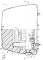
- Figure 2 is a horizontally sectioned view along line II-II of figure 1 in a first condition of the headrest,
- Figure 3 is a view same as figure 2 in a second condition of the headrest,
- Figure 4 is a vertically sectioned view along line IV-IV of figure 4 in a first angularly adjusted condition of the headrest,
- Figure 5 is a view same as figure 4 showing the headrest in a second angularly adjusted condition,
- Figure 6 is a vertically sectioned view according line VI-VI of figure 1, and
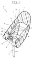
- Figure 7 is a perspective exploded view of a detail of the headrest according to the invention.
-
- In the drawings,
reference numeral 1 generally designates a headrest for motor-vehicles, essentially formed by a yelding body orcushion 2, normally made of foamed plastic material, incorporating a load-bearingframework 3 normally made of rigid moulded plastic material, and a pair of support rods 4 parallel to each other and on which the load-bearingframework 3 is coupled, such as clarified herebelow, in a slidable and swinging fashion. This coupling enables, in use, adjustment both of the height positioning and of the angular positioning of thecushion 2 relative to the top of the backrest of a motor-vehicle seat on which thehead rest 1 is installed. - The support rods 4 each include a
lower portion 5, intended to be rigidly connected to the structure of the seat backrest, in a known way, and anupper portion 6 which, in the case of the shown example, forms an angle with thelower portion 5. Theupper portion 6 of each support rod 4 conveniently comprises a metal core 6a on which a rigid plastic material lining 6b is overmoulded. In alternative, each support road 4 may be fully metallic. In any case, theupper portion 6 of each support road 4 is provided along one side thereof with a respective vertical row of positioningnotches 7 having preferably a quadrangular cross-section. Thenotches 7 of the two support rods 4 are both facing towards the same side, i.e. to the right with reference to figures 1 through 3. - The load-bearing
framework 3 is formed by two half-shells tubular housing 9. -
Reference numeral 10 designates an intermediate hollow body, also made of moulded plastic material, fitted between the half-shells framework 3. As shown in detail in figure 7, the intermediatehollow body 10 comprises a centralelongated portion 11 having a rounded outer surface and a shape complementary to that of thecentral housing 9, and two box-like enlargedend portions 12 each formed with a respective uppertubular guide appendage 13 into which theupper portion 6 of a respective support rod 4 is slidably fitted. - The lateral walls facing towards the same side, namely to the left with reference to figures 2,3 and 7, of the box-
like end portions 12 are formed with respective series of through openings 14 (in the shown example three of these openings are provided) arranged in a fan-like fashion. - The intermediate
hollow body 10 is open at the front so as to enable, during assembling, fitting thereinto aslider member 15, also formed by one rigid moulded plastic material piece, which is movable perpendicularly to the support rods 4, such as clarified herebelow. - As also illustrated in detail in figure 7, the
slider member 15 comprises an elongatedcentral portion 16 housed within thecentral portion 11 of the intermediatehollow body 10, and two enlargedend portions 17 fitted within the box-like ends 12 of theintermediate body 10. - The enlarged
end portions 17 are formed on the same side, namely the left side with reference to figures 2,3 and 7, with respective series oftooth projections 18 complementary to the throughopenings 14 and facing towards these openings. Moreover the enlargedends 17 are formed withrespective apertures 19, corresponding to thetubular guide appendages 13 of theintermediate body 10 and, in the assembled condition, are passed through by the upper portions of the support rods 4. - The
slider member 15 is slidably mounted within theintermediate body 10 between an advanced position shown in figure 2, in which thetooth appendages 18 pass through theopenings 14 and project outside thereof, and a retracted position depicted in figure 3, in which the tooth appendages 18 substantially do not project outside of theopenings 14. In either position thetooth appendages 18 do engage and, respectively, do not engage corresponding seats or openings of twofanlike series 20, formed in the corresponding lateral walls of the half-shell 3a of the load-bearingframework 3. -
Reference numerals 21 designate two metal V-shaped wire springs having respective springingarms 22 reacting againstcorresponding reaction surfaces 23 of the box-like ends 12 of theintermediate body 10, opposite to the throughopenings 14. Eachwire spring 21 is provided with afurther arm 28 which is rigidly fixed to theslider member 15 so as to have a central portion exposed along thecorresponding aperture 19, such as clearly depicted in figures 2 and 3. These exposed central portions of thearms 28 are designed to engage thenotches 7 of theupper portions 6 of the two support rods 4 in the way shown in figure 2, i.e. when theslider member 15 is placed in the advanced position. The springingarms 22 of thewire springs 21 act as thrust resilient elements intended to hold theslider member 15 in this advanced position, whereby relative displacement between the load-bearingframework 3 with theyelding body 2 and the support rods 4 is prevented. Moreover, in this advanced position of theslider member 15 any angular displacement of the load-bearingframework 3 with theyelding body 2 relative to the supports rods 4 is also prevented by engagement of thetooth appendages 18 of theslider member 15 within corresponding seats of the two fan-like series 20 of the half-shell 3a, across thethrough openings 14 of theintermediate body 10. -
Reference numeral 24 designates a control member formed as a manually operable push-button arranged at one side of the yeldingbody 2 of theheadrest 1 and rigidly connected to astem 25 which is extending along ahollow guide appendage 29 of the load-bearingframework 3 and whosefree end 26 is engaged, by means of a snap-fit coupling, within a slottedlateral appendage 27 of theslider member 15. - The control push-
button 24 can be operated from outside to displace theslider member 15 from the advanced position of figure 2 to the retracted position of figure 3, in which as already pointed out it is displaced to the right with reference to that figure, against the action of the springingarms 22 of thewire springs 21. Owing to this displacement firstly the lockingarms 28 are withdrawn from thenotches 7 of the support rods 4, whereby theyelding body 2 can be moved upwardly or downwardly, by virtue of sliding of thetubular guides 13 of theintermediate body 10, and thus of the load-bearingframework 3, along theupper portions 6 of the supports rods 4, to perform height adjustment of the headrest relative to the backrest of a motor-vehicle seat. Then, a further retraction of theslider member 15 relative to theintermediate body 10 causes disengagement of thetooth appendages 18 from theseats 20 of the half-shell 3a of the load-bearingframework 3, which enables the latter, together with theyelding body 2, to be angularly displaced relative to the assembly formed by the support rods 4, theslider member 15 and theintermediate body 10. This tilting motion, allowed by the rotatable coupling between thecentral portion 11 of theintermediate body 10 and thecentral housing 9 of the load-bearingframework 3, enables adjusting the tilt of the yeldingbody 2 relative to the seat backrest, between the two end positions depicted in figures 4 and 5, respectively. - Upon release of the push-
button 24, the springingarms 22 of thewire springs 21 move theslider member 15 back to the advanced position, thus performing firstly engagement between thetooth appendages 18 and the corresponding openings of the two fan-like series 20, and subsequently engagement of thearms 28 into thecorresponding positioning notches 7 of the support rods 4. - It will be apparent from the forgoing that the locking and unlocking operation between the yelding
body 2 and the support rods 4, and accordingly both the height adjustment and the tilt adjustment of the yeldingbody 2, are made extremely convenient and easy since requiring operation of a single control member, namely the push-button 24. - In case the user intends only to adjust the height of the yelding
body 2, without changing the angular positioning thereof, it will be sufficient to push only partially, instead of fully, the push-button 24 to the position shown with dotted lines in figure 3. In that case the lockingarms 28 of thesprings 21 shall be disengaged from therelated notches 7 of the support rods 4, but thetooth projections 18 shall not be disengaged from the related series of fan-like openings 20, thus releasing upward or downward displacement of theyelding body 2 but not tilting thereof. To make selection by the user of one or the other adjustment mode easier, positioning means may be provided, for instance of the elastic snap-fit type, to releasably stop thestem 25 of the push-button 24 in a partially advanced and, respectively, in a fully advanced position. - It is to be pointed out that the push-
button 24 may be replaced by a different control member, such as for instance a rotary knob or a swinging lever. - Naturally, the details of construction and the embodiments may be widely varied with respect to what has been disclosed and illustrated, without thereby departing from the scope of the present invention such as defined in the appended claims.
Claims (9)
- Headrest (1) for motor-vehicles seats, comprising a yelding body (2) incorporating a load-bearing framework (3), a pair of parallel support rods (4) slidably coupled with said load-bearing framework (3) and projecting outside of said yelding body (2), locking means (28) adapted to engage corresponding positioning notches (7) of said support rods (4) to prevent relative displacement between said support rods (4) and said load-bearing framework (3), and manually operable release means (15,24) of said locking means (28), characterised in that:the locking means (28) are carried by a slider member (15) displaceable in said load-bearing framework (3) in a direction perpendicular to said support rods (4) from an engaged position to a disengaged position relative to said positioning notches (7) of the support rods (4), against the action of resilient thrust means (22),said yelding body (2) is swingable relative to said slider member (15), and between said load-bearing framework (3) and said slider member (15) releasable angular positioning means (18,20) are provided to adjust tilt of said yelding body (2) relative to said support rods (4).
- Headrest according to claim 1, characterised in that said angular positioning means (18,20) can be disengaged by said manually operable release means (15, 24).
- Headrest according to claim 1, characterised in that said angular positioning means comprise at least one tooth projection (18) extending laterally of said slider member (15) and at least one series of complementary seats arranged in a fan-like fashion (20) in said load-bearing framework (3) and selectively engageable by said at least one tooth projection (18).
- Headrest according to claim 3, characterised in that between said load-bearing framework (3) and said slider member (15) an intermediate hollow body (10) is interposed on which said load-bearing framework (3) is tiltably mounted; said intermediate hollow body (10) slidably supporting said slider member (15), being slidably mounted on said support rods (4), and being passed through by said at least one tooth appendage (18) of said slider member (15).
- Headrest according to claim 4, characterised in that said intermediate hollow body (10) is formed with a pair of tubular guide appendages (13) for said support rods (4).
- Headrest according to claim 2, characterised in that said release means comprise a control member (24) movable over a first operative stroke to disengage said locking means (28) and a second operative stroke to disengage said angular positioning means (18,20), respectively.
- Headrest according to claim 6, characterised in that said release means comprise a push-button (24) arranged at one side of said yelding body (2) and operable from outside to displace said slider member (15) from said engaged position towards said disengaged position.
- Headrest according to claim 4, characterised in that said resilient thrust means comprise a pair of wire springs (21) having a first arm (22) reacting against said intermediate hollow body (10) and a second arm (28) forming said locking means.
- Headrest according to claim 4, characterised in that said load-bearing framework (3) is formed by two half-shells (3a,3b) coupled to each other by snap-fit connecting elements (8) and defining therebetween a central seat (9) rotatably supported on said intermediate hollow body (10).
Priority Applications (2)
| Application Number | Priority Date | Filing Date | Title |
|---|---|---|---|
| EP98830415A EP0970846A1 (en) | 1998-07-09 | 1998-07-09 | A headrest for motor-vehicle |
| BR9905657-7A BR9905657A (en) | 1998-07-09 | 1999-07-06 | Headrest for automotive vehicle seats |
Applications Claiming Priority (1)
| Application Number | Priority Date | Filing Date | Title |
|---|---|---|---|
| EP98830415A EP0970846A1 (en) | 1998-07-09 | 1998-07-09 | A headrest for motor-vehicle |
Publications (1)
| Publication Number | Publication Date |
|---|---|
| EP0970846A1 true EP0970846A1 (en) | 2000-01-12 |
Family
ID=8236709
Family Applications (1)
| Application Number | Title | Priority Date | Filing Date |
|---|---|---|---|
| EP98830415A Withdrawn EP0970846A1 (en) | 1998-07-09 | 1998-07-09 | A headrest for motor-vehicle |
Country Status (2)
| Country | Link |
|---|---|
| EP (1) | EP0970846A1 (en) |
| BR (1) | BR9905657A (en) |
Cited By (19)
| Publication number | Priority date | Publication date | Assignee | Title |
|---|---|---|---|---|
| FR2832365A1 (en) * | 2001-11-21 | 2003-05-23 | Cera | Adjustable head support comprises mounting pin on seat back, support fixed on pin and support cushion movable in three directions relative to fixed support |
| WO2004098921A3 (en) * | 2003-05-09 | 2004-12-09 | Daimler Chrysler Ag | Comfort rest for a rear seat |
| WO2005068252A1 (en) * | 2004-01-19 | 2005-07-28 | Kongsberg Automotive Ab | Improved head restraint |
| WO2005068251A1 (en) * | 2004-01-19 | 2005-07-28 | Kongsberg Automotive Ab | Improved head restraint |
| FR2886232A1 (en) * | 2005-05-25 | 2006-12-01 | Faurecia Sieges Automobile | Head-restraint for motor vehicle`s seat, has structure movably mounted such that unlocking of head-restraint is controlled between two positions in which portions prevent and authorize structure`s movement along bar`s axis, respectively |
| US7562936B1 (en) | 2008-08-29 | 2009-07-21 | Lear Corporation | Adjustable head restraint assembly for vehicle seats |
| US7621598B2 (en) | 2006-10-03 | 2009-11-24 | Lear Corporation | Adjustable head restraint for a vehicle seat |
| DE102009036896B3 (en) * | 2009-03-16 | 2010-09-16 | Grammer Ag | Head restraint for vehicle seat, has primary locking element and/or secondary locking element assigned to slidegate valve that is led by guidance device and moved to rotational axis of upholstery support |
| CN101296637B (en) * | 2004-04-09 | 2011-04-27 | 佛吉亚汽车内部系统公司 | Slideable armrest |
| US8025338B2 (en) | 2008-03-28 | 2011-09-27 | Lear Corporation | Adjustable head restraint system for an automotive vehicle seat |
| US8157328B2 (en) | 2008-09-22 | 2012-04-17 | Lear Corporation | Adjustable vehicle head restraint assembly for a vehicle seat |
| US8376465B2 (en) | 2009-07-07 | 2013-02-19 | Lear Corporation | Adjustable head restraint assembly for vehicle seats |
| WO2013107868A1 (en) * | 2012-01-19 | 2013-07-25 | Johnson Controls Gmbh | Articulating head restraint |
| DE102013007633A1 (en) | 2013-05-06 | 2014-11-06 | Grammer Ag | Headrest with locking device |
| US9475414B2 (en) | 2013-11-05 | 2016-10-25 | Lear Corporation | Adjustable head restraint assembly for vehicle seats |
| CN107640072A (en) * | 2016-07-20 | 2018-01-30 | 李尔公司 | Seat-assembly with adjustable head restraint assembly |
| WO2018020179A1 (en) * | 2016-07-28 | 2018-02-01 | Cera Tsc | Headrest for a motor vehicle seat |
| FR3102723A1 (en) * | 2019-10-30 | 2021-05-07 | Tesca France | Motor vehicle seat headrest |
| DE102024119482A1 (en) * | 2024-07-09 | 2026-01-15 | Illinois Tool Works Inc. | Headrest for a vehicle seat with a headrest guidance arrangement and headrest guidance arrangement for a headrest |
Citations (6)
| Publication number | Priority date | Publication date | Assignee | Title |
|---|---|---|---|---|
| GB1537551A (en) * | 1977-07-08 | 1978-12-29 | Uop Inc | Head rests for vehicle seats |
| US4674792A (en) * | 1985-06-07 | 1987-06-23 | Ikeda Bussan Co, Ltd. | Position adjustable see-through headrest |
| DE4017148C1 (en) * | 1990-05-28 | 1991-12-12 | Eugen Otto 4010 Hilden De Butz | Car seat headrest with support rod(s) in backrest - has incline adjuster with radially outwards spring-loaded, adjustable sliding face |
| EP0582765A1 (en) * | 1992-08-11 | 1994-02-16 | Gestind M.B. Manifattura Di Bruzolo S.P.A | A headrest for motor vehicle seats |
| EP0770512A1 (en) * | 1995-10-23 | 1997-05-02 | Gestind M.B. Manifattura Di Bruzolo S.P.A | Headrest for motor-vehicle seats |
| GB2315997A (en) * | 1996-08-09 | 1998-02-18 | Rover Group | Adjustable head rest assembly |
-
1998
- 1998-07-09 EP EP98830415A patent/EP0970846A1/en not_active Withdrawn
-
1999
- 1999-07-06 BR BR9905657-7A patent/BR9905657A/en not_active Application Discontinuation
Patent Citations (6)
| Publication number | Priority date | Publication date | Assignee | Title |
|---|---|---|---|---|
| GB1537551A (en) * | 1977-07-08 | 1978-12-29 | Uop Inc | Head rests for vehicle seats |
| US4674792A (en) * | 1985-06-07 | 1987-06-23 | Ikeda Bussan Co, Ltd. | Position adjustable see-through headrest |
| DE4017148C1 (en) * | 1990-05-28 | 1991-12-12 | Eugen Otto 4010 Hilden De Butz | Car seat headrest with support rod(s) in backrest - has incline adjuster with radially outwards spring-loaded, adjustable sliding face |
| EP0582765A1 (en) * | 1992-08-11 | 1994-02-16 | Gestind M.B. Manifattura Di Bruzolo S.P.A | A headrest for motor vehicle seats |
| EP0770512A1 (en) * | 1995-10-23 | 1997-05-02 | Gestind M.B. Manifattura Di Bruzolo S.P.A | Headrest for motor-vehicle seats |
| GB2315997A (en) * | 1996-08-09 | 1998-02-18 | Rover Group | Adjustable head rest assembly |
Cited By (28)
| Publication number | Priority date | Publication date | Assignee | Title |
|---|---|---|---|---|
| FR2832365A1 (en) * | 2001-11-21 | 2003-05-23 | Cera | Adjustable head support comprises mounting pin on seat back, support fixed on pin and support cushion movable in three directions relative to fixed support |
| WO2004098921A3 (en) * | 2003-05-09 | 2004-12-09 | Daimler Chrysler Ag | Comfort rest for a rear seat |
| US7427108B2 (en) | 2004-01-19 | 2008-09-23 | Kongsberg Automotive Ab | Head restraint for motor vehicle |
| WO2005068252A1 (en) * | 2004-01-19 | 2005-07-28 | Kongsberg Automotive Ab | Improved head restraint |
| WO2005068251A1 (en) * | 2004-01-19 | 2005-07-28 | Kongsberg Automotive Ab | Improved head restraint |
| CN101296637B (en) * | 2004-04-09 | 2011-04-27 | 佛吉亚汽车内部系统公司 | Slideable armrest |
| FR2886232A1 (en) * | 2005-05-25 | 2006-12-01 | Faurecia Sieges Automobile | Head-restraint for motor vehicle`s seat, has structure movably mounted such that unlocking of head-restraint is controlled between two positions in which portions prevent and authorize structure`s movement along bar`s axis, respectively |
| US7621598B2 (en) | 2006-10-03 | 2009-11-24 | Lear Corporation | Adjustable head restraint for a vehicle seat |
| US8025338B2 (en) | 2008-03-28 | 2011-09-27 | Lear Corporation | Adjustable head restraint system for an automotive vehicle seat |
| US7562936B1 (en) | 2008-08-29 | 2009-07-21 | Lear Corporation | Adjustable head restraint assembly for vehicle seats |
| US8157328B2 (en) | 2008-09-22 | 2012-04-17 | Lear Corporation | Adjustable vehicle head restraint assembly for a vehicle seat |
| DE102009036896B3 (en) * | 2009-03-16 | 2010-09-16 | Grammer Ag | Head restraint for vehicle seat, has primary locking element and/or secondary locking element assigned to slidegate valve that is led by guidance device and moved to rotational axis of upholstery support |
| US8376465B2 (en) | 2009-07-07 | 2013-02-19 | Lear Corporation | Adjustable head restraint assembly for vehicle seats |
| DE102010030783B4 (en) | 2009-07-07 | 2023-05-17 | Lear Corp. | Adjustable head restraint assembly for vehicle seats and method of assembling an adjustable head restraint assembly |
| CN104053574A (en) * | 2012-01-19 | 2014-09-17 | 约翰逊控股公司 | Head restraint with adjustable angle of inclination |
| US9656580B2 (en) | 2012-01-19 | 2017-05-23 | Johnson Controls Gmbh | Inclination-adjustable head restraint |
| WO2013107868A1 (en) * | 2012-01-19 | 2013-07-25 | Johnson Controls Gmbh | Articulating head restraint |
| DE102013007633B4 (en) | 2013-05-06 | 2022-01-05 | Grammer Aktiengesellschaft | Headrest with locking device |
| US9114744B2 (en) | 2013-05-06 | 2015-08-25 | Grammer Ag | Latchable headrest |
| DE102013007633A1 (en) | 2013-05-06 | 2014-11-06 | Grammer Ag | Headrest with locking device |
| US9475414B2 (en) | 2013-11-05 | 2016-10-25 | Lear Corporation | Adjustable head restraint assembly for vehicle seats |
| CN107640072A (en) * | 2016-07-20 | 2018-01-30 | 李尔公司 | Seat-assembly with adjustable head restraint assembly |
| US10314401B2 (en) * | 2016-07-20 | 2019-06-11 | Lear Corporation | Seat assembly having an adjustable head restraint assembly |
| CN107640072B (en) * | 2016-07-20 | 2020-04-07 | 李尔公司 | Seat assembly with adjustable head restraint assembly |
| FR3054502A1 (en) * | 2016-07-28 | 2018-02-02 | Cera Tsc | HEADREST FOR THE SEAT OF A MOTOR VEHICLE |
| WO2018020179A1 (en) * | 2016-07-28 | 2018-02-01 | Cera Tsc | Headrest for a motor vehicle seat |
| FR3102723A1 (en) * | 2019-10-30 | 2021-05-07 | Tesca France | Motor vehicle seat headrest |
| DE102024119482A1 (en) * | 2024-07-09 | 2026-01-15 | Illinois Tool Works Inc. | Headrest for a vehicle seat with a headrest guidance arrangement and headrest guidance arrangement for a headrest |
Also Published As
| Publication number | Publication date |
|---|---|
| BR9905657A (en) | 2000-11-28 |
Similar Documents
| Publication | Publication Date | Title |
|---|---|---|
| EP0970846A1 (en) | A headrest for motor-vehicle | |
| US6860564B2 (en) | Vehicular seat assembly having a cam driven self positioning head restraint | |
| US5020855A (en) | Adjustable headrest | |
| US6270161B1 (en) | Headrest for motor-vehicle seats | |
| US5895094A (en) | Headrest apparatus for vehicle seat | |
| EP0604375B1 (en) | Armrest for motor-vehicle rear seats | |
| US10314401B2 (en) | Seat assembly having an adjustable head restraint assembly | |
| US20080012403A1 (en) | Vehicle seat | |
| US3328082A (en) | Headrest | |
| US20030178876A1 (en) | Multi-task mid-pivot chair control mechanism | |
| US20220097577A1 (en) | Child safety seat assembly | |
| JP4583613B2 (en) | Vehicle seat support mechanism | |
| US4455009A (en) | Adjustable vehicle seat mounting device | |
| EP1161904A1 (en) | Chair with seat and backrest that oscillate in a synchronized way | |
| PL181403B1 (en) | Headrest for motor vehicle seats | |
| JPH0775575B2 (en) | Adjustable head support | |
| JP4790727B2 (en) | Adjustable seat | |
| EP0819571A2 (en) | A headrest for motor vehicle seats | |
| KR20190035292A (en) | Controlling apparatus of headrest | |
| JPH0133368B2 (en) | ||
| JP3776749B2 (en) | Chair | |
| JPS6328818B2 (en) | ||
| KR200147148Y1 (en) | Armrest for a car | |
| JP3434196B2 (en) | Seat mounting structure | |
| JPH024819Y2 (en) |
Legal Events
| Date | Code | Title | Description |
|---|---|---|---|
| PUAI | Public reference made under article 153(3) epc to a published international application that has entered the european phase |
Free format text: ORIGINAL CODE: 0009012 |
|
| AK | Designated contracting states |
Kind code of ref document: A1 Designated state(s): AT BE CH CY DE DK ES FI FR GB GR IE IT LI LU MC NL PT SE |
|
| AX | Request for extension of the european patent |
Free format text: AL;LT;LV;MK;RO;SI |
|
| AKX | Designation fees paid | ||
| STAA | Information on the status of an ep patent application or granted ep patent |
Free format text: STATUS: THE APPLICATION IS DEEMED TO BE WITHDRAWN |
|
| 18D | Application deemed to be withdrawn |
Effective date: 20000713 |
|
| REG | Reference to a national code |
Ref country code: DE Ref legal event code: 8566 |