EP0971116B1 - Moteur à combustion interne - Google Patents
Moteur à combustion interne Download PDFInfo
- Publication number
- EP0971116B1 EP0971116B1 EP99109450A EP99109450A EP0971116B1 EP 0971116 B1 EP0971116 B1 EP 0971116B1 EP 99109450 A EP99109450 A EP 99109450A EP 99109450 A EP99109450 A EP 99109450A EP 0971116 B1 EP0971116 B1 EP 0971116B1
- Authority
- EP
- European Patent Office
- Prior art keywords
- intake passages
- internal combustion
- combustion engine
- engine according
- pair
- Prior art date
- Legal status (The legal status is an assumption and is not a legal conclusion. Google has not performed a legal analysis and makes no representation as to the accuracy of the status listed.)
- Expired - Lifetime
Links
Images


Classifications
-
- F—MECHANICAL ENGINEERING; LIGHTING; HEATING; WEAPONS; BLASTING
- F02—COMBUSTION ENGINES; HOT-GAS OR COMBUSTION-PRODUCT ENGINE PLANTS
- F02M—SUPPLYING COMBUSTION ENGINES IN GENERAL WITH COMBUSTIBLE MIXTURES OR CONSTITUENTS THEREOF
- F02M35/00—Combustion-air cleaners, air intakes, intake silencers, or induction systems specially adapted for, or arranged on, internal-combustion engines
- F02M35/10—Air intakes; Induction systems
- F02M35/10209—Fluid connections to the air intake system; their arrangement of pipes, valves or the like
- F02M35/10216—Fuel injectors; Fuel pipes or rails; Fuel pumps or pressure regulators
-
- F—MECHANICAL ENGINEERING; LIGHTING; HEATING; WEAPONS; BLASTING
- F01—MACHINES OR ENGINES IN GENERAL; ENGINE PLANTS IN GENERAL; STEAM ENGINES
- F01L—CYCLICALLY OPERATING VALVES FOR MACHINES OR ENGINES
- F01L1/00—Valve-gear or valve arrangements, e.g. lift-valve gear
- F01L1/02—Valve drive
- F01L1/04—Valve drive by means of cams, camshafts, cam discs, eccentrics or the like
- F01L1/047—Camshafts
- F01L1/053—Camshafts overhead type
- F01L1/0532—Camshafts overhead type the cams being directly in contact with the driven valve
-
- F—MECHANICAL ENGINEERING; LIGHTING; HEATING; WEAPONS; BLASTING
- F01—MACHINES OR ENGINES IN GENERAL; ENGINE PLANTS IN GENERAL; STEAM ENGINES
- F01L—CYCLICALLY OPERATING VALVES FOR MACHINES OR ENGINES
- F01L1/00—Valve-gear or valve arrangements, e.g. lift-valve gear
- F01L1/26—Valve-gear or valve arrangements, e.g. lift-valve gear characterised by the provision of two or more valves operated simultaneously by same transmitting-gear; peculiar to machines or engines with more than two lift-valves per cylinder
-
- F—MECHANICAL ENGINEERING; LIGHTING; HEATING; WEAPONS; BLASTING
- F01—MACHINES OR ENGINES IN GENERAL; ENGINE PLANTS IN GENERAL; STEAM ENGINES
- F01L—CYCLICALLY OPERATING VALVES FOR MACHINES OR ENGINES
- F01L1/00—Valve-gear or valve arrangements, e.g. lift-valve gear
- F01L1/46—Component parts, details, or accessories, not provided for in preceding subgroups
-
- F—MECHANICAL ENGINEERING; LIGHTING; HEATING; WEAPONS; BLASTING
- F02—COMBUSTION ENGINES; HOT-GAS OR COMBUSTION-PRODUCT ENGINE PLANTS
- F02B—INTERNAL-COMBUSTION PISTON ENGINES; COMBUSTION ENGINES IN GENERAL
- F02B31/00—Modifying induction systems for imparting a rotation to the charge in the cylinder
- F02B31/08—Modifying induction systems for imparting a rotation to the charge in the cylinder having multiple air inlets
- F02B31/085—Modifying induction systems for imparting a rotation to the charge in the cylinder having multiple air inlets having two inlet valves
-
- F—MECHANICAL ENGINEERING; LIGHTING; HEATING; WEAPONS; BLASTING
- F02—COMBUSTION ENGINES; HOT-GAS OR COMBUSTION-PRODUCT ENGINE PLANTS
- F02B—INTERNAL-COMBUSTION PISTON ENGINES; COMBUSTION ENGINES IN GENERAL
- F02B63/00—Adaptations of engines for driving pumps, hand-held tools or electric generators; Portable combinations of engines with engine-driven devices
- F02B63/06—Adaptations of engines for driving pumps, hand-held tools or electric generators; Portable combinations of engines with engine-driven devices for pumps
-
- F—MECHANICAL ENGINEERING; LIGHTING; HEATING; WEAPONS; BLASTING
- F02—COMBUSTION ENGINES; HOT-GAS OR COMBUSTION-PRODUCT ENGINE PLANTS
- F02M—SUPPLYING COMBUSTION ENGINES IN GENERAL WITH COMBUSTIBLE MIXTURES OR CONSTITUENTS THEREOF
- F02M37/00—Apparatus or systems for feeding liquid fuel from storage containers to carburettors or fuel-injection apparatus; Arrangements for purifying liquid fuel specially adapted for, or arranged on, internal-combustion engines
- F02M37/04—Feeding by means of driven pumps
- F02M37/06—Feeding by means of driven pumps mechanically driven
-
- F—MECHANICAL ENGINEERING; LIGHTING; HEATING; WEAPONS; BLASTING
- F02—COMBUSTION ENGINES; HOT-GAS OR COMBUSTION-PRODUCT ENGINE PLANTS
- F02B—INTERNAL-COMBUSTION PISTON ENGINES; COMBUSTION ENGINES IN GENERAL
- F02B75/00—Other engines
- F02B75/12—Other methods of operation
- F02B2075/125—Direct injection in the combustion chamber for spark ignition engines, i.e. not in pre-combustion chamber
-
- F—MECHANICAL ENGINEERING; LIGHTING; HEATING; WEAPONS; BLASTING
- F02—COMBUSTION ENGINES; HOT-GAS OR COMBUSTION-PRODUCT ENGINE PLANTS
- F02B—INTERNAL-COMBUSTION PISTON ENGINES; COMBUSTION ENGINES IN GENERAL
- F02B2275/00—Other engines, components or details, not provided for in other groups of this subclass
- F02B2275/18—DOHC [Double overhead camshaft]
-
- F—MECHANICAL ENGINEERING; LIGHTING; HEATING; WEAPONS; BLASTING
- F02—COMBUSTION ENGINES; HOT-GAS OR COMBUSTION-PRODUCT ENGINE PLANTS
- F02B—INTERNAL-COMBUSTION PISTON ENGINES; COMBUSTION ENGINES IN GENERAL
- F02B2275/00—Other engines, components or details, not provided for in other groups of this subclass
- F02B2275/48—Tumble motion in gas movement in cylinder
-
- F—MECHANICAL ENGINEERING; LIGHTING; HEATING; WEAPONS; BLASTING
- F02—COMBUSTION ENGINES; HOT-GAS OR COMBUSTION-PRODUCT ENGINE PLANTS
- F02B—INTERNAL-COMBUSTION PISTON ENGINES; COMBUSTION ENGINES IN GENERAL
- F02B23/00—Other engines characterised by special shape or construction of combustion chambers to improve operation
- F02B23/08—Other engines characterised by special shape or construction of combustion chambers to improve operation with positive ignition
- F02B23/10—Other engines characterised by special shape or construction of combustion chambers to improve operation with positive ignition with separate admission of air and fuel into cylinder
- F02B23/104—Other engines characterised by special shape or construction of combustion chambers to improve operation with positive ignition with separate admission of air and fuel into cylinder the injector being placed on a side position of the cylinder
-
- F—MECHANICAL ENGINEERING; LIGHTING; HEATING; WEAPONS; BLASTING
- F02—COMBUSTION ENGINES; HOT-GAS OR COMBUSTION-PRODUCT ENGINE PLANTS
- F02M—SUPPLYING COMBUSTION ENGINES IN GENERAL WITH COMBUSTIBLE MIXTURES OR CONSTITUENTS THEREOF
- F02M35/00—Combustion-air cleaners, air intakes, intake silencers, or induction systems specially adapted for, or arranged on, internal-combustion engines
- F02M35/10—Air intakes; Induction systems
- F02M35/10006—Air intakes; Induction systems characterised by the position of elements of the air intake system in direction of the air intake flow, i.e. between ambient air inlet and supply to the combustion chamber
- F02M35/10078—Connections of intake systems to the engine
- F02M35/10085—Connections of intake systems to the engine having a connecting piece, e.g. a flange, between the engine and the air intake being foreseen with a throttle valve, fuel injector, mixture ducts or the like
-
- Y—GENERAL TAGGING OF NEW TECHNOLOGICAL DEVELOPMENTS; GENERAL TAGGING OF CROSS-SECTIONAL TECHNOLOGIES SPANNING OVER SEVERAL SECTIONS OF THE IPC; TECHNICAL SUBJECTS COVERED BY FORMER USPC CROSS-REFERENCE ART COLLECTIONS [XRACs] AND DIGESTS
- Y02—TECHNOLOGIES OR APPLICATIONS FOR MITIGATION OR ADAPTATION AGAINST CLIMATE CHANGE
- Y02T—CLIMATE CHANGE MITIGATION TECHNOLOGIES RELATED TO TRANSPORTATION
- Y02T10/00—Road transport of goods or passengers
- Y02T10/10—Internal combustion engine [ICE] based vehicles
- Y02T10/12—Improving ICE efficiencies
Definitions
- This invention relates to an internal combustion engine comprising a cylinder block, a cylinder head fastened to said cylinder block, at least one cylinder formed in said cylinder block, said cylinder having a combustion chamber formed by a reciprocable piston within said cylinder and by said cylinder head, a first pair of intake passages opening into said combustion chamber and an injector for injecting fuel into said combustion chamber.
- Engines to be mounted on vehicles include one, for example, that comprises a pair of intake passages opening to a combustion chamber with the upstream sides of the paired intake passages joined together, and an injector for injecting fuel into the combustion chamber.
- the cross-sectional shape of the intake passage is in most cases circular. Therefore, when it is intended to use a pair of intake passages opening to the combustion chamber and to dispose an injector for injecting fuel into the combustion chamber in a position between the paired intake passages, the intake passages interfere with the injector and makes efficient layout difficult. As a result, it is inevitable to take measures by increasing the size of the engine or reducing the diameters of the intake passages.
- the circular cross section of the intake passage gives rise to another problem: To form the paired intake passages, the part between the intake passages must be thickened with the passage material, which results in the increase in weight.
- this objective is solved in that said first pair of intake passages being provided with attachment recesses for accommodating said injector.
- said injector is disposed between said first pair of intake passages and at their respective undersides. This ensures that the respective intake passages may be provided with desired angles with respect to the cylinder bore axis.
- said first pair of intake passages being provided within said cylinder head and that at the respective upstream ends a respective second pair of intake passages are connected being the downstream part of a single intake passage.
- a certain precompression of the intake air amount is achievable when the respective cross-sections of said first and second pairs of intake passages are increasing starting from respective openings into the combustion chamber of said first pair of intake passages.
- the internal combustion engine comprises; a pair of intake passages opening to a combustion chamber with the upstream sides of the paired intake passages joined together, and an injector for injecting fuel into the combustion chamber, wherein the injector is disposed at a position below and between the paired intake passages and that a recessed attachment space is provided so that the injector may be disposed to enter the space below and between the paired intake passages.
- the structure is made compact and easy to secure the space for installing the injector while securing the intake amount as the recessed attachment space is provided so that the injector may be disposed to enter the space below and between the paired intake passages.
- Another embodiment of the present invention is characterized in that the cross-sections of the paired intake passages are square-shaped.
- the part between the intake passages need not be thickened because the cross-sections of the paired intake passages are square-shaped.
- the internal combustion engine is made lightweight and compact.
- a further embodiment of the present invention is characterized in that a swirl control valve is provided in one of the intake passages and that the injector is disposed on the downstream side of the swirl control valve.
- the structure is made lightweight and compact while securing the same flow rate because the swirl control valve is disposed efficiently.
- the internal combustion engine 1 is of a three-cylinder, four-stroke-cycle type comprising a cylinder block 2 and a cylinder head 3 placed on the cylinder block 2.
- a head cover 4 is secured to the cylinder head 3.
- Pistons 5 for reciprocating motion are disposed in cylinders 2a formed in the cylinder block 2.
- Each of combustion chambers 6 is formed with the piston 5 and the cylinder head 3.
- the cylinder head 3 is provided with two intake passages 7 and two exhaust passages 8 respectively corresponding to each of the three cylinders.
- the openings 7a of the intake passages 7 and the openings 8a of the exhaust passages 8 are formed to face the combustion chamber 6.
- the cylinder head 3 is provided with an intake passage 30 communicating with the intake passages 7.
- the intake passage 30 is provided with a swirl control valve 31 for producing a swirl flow in the low revolution range.
- the cylinder head 3 is also provided with an exhaust pipe 32 communicating with the exhaust passages 8.
- the cylinder head 3 is further provided with an injector 33 for injecting fuel directly into the combustion chamber 6.
- the cylinder head 3 is further provided with intake valves 9 and exhaust valves 10 for respectively opening and closing the intake passages 7 and exhaust passages 8.
- An ignition plug 90 is provided in the central part of the cylinder head 3, with its igniting portion 90a facing the center of the combustion chamber 6.
- the constitutions of the intake valve 9 and the exhaust valve 10 are similar to each other.
- Cam shafts 11 and 12 of a valve drive mechanism are disposed over the intake valves 9 and the exhaust valves 10 and made rotatable in journal bearing portions 3g and 3h formed in the cylinder head 3.
- Cam caps 20 and 21 are tightened over the journal bearing portions 3g and 3h by means of bolts 22 and 23.
- the camshaft 11 on the intake side is provided with cams 11a at positions corresponding to the intake valves 9.
- the camshaft 12 on the exhaust side is formed with cams 12a at positions corresponding to the exhaust valves 10.
- the camshafts 11 and 12 are provided with gears (not shown) so that the camshafts rotate as interlocked with the crankshaft.
- the cams 11 and 12 rotate, the cams 11a drive the intake valves 9 while the cams 12a drive the exhaust valves 10 to open and close the openings 7a of the intake passages 7 and the openings 8a of the exhaust passages 8 with predetermined timing.
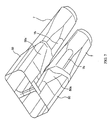
- each intake passage 7 formed in the cylinder head 3 is formed to be square-shaped in cross-section.
- An intake pipe or intake passage 30 is connected to the intake side of the cylinder head 3.
- Two intake passages 50 are formed in each of the three intake pipes 30 corresponding to the three cylinders.
- the intake passages 50 of the intake pipe 30 are square-shaped in cross section as shown in FIG. 4 and communicate with the intake passages 7 in the cylinder head 3.
- the swirl control valve 31 is disposed in one of the intake passages 50 and driven with a driving motor 35.
- Swirl is produced in the low revolution range as follows:
- the driving motor 35 is controlled according to the operating state such as revolution of the engine, the swirl control valve 31 is driven with the driving motor 35 so as to control the intake air amount, and the air flow rate through the other intake passage 50 is controlled.
- the upstream sides of the intake passages 50 of the intake pipe 30 are joined together.
- the injector 33 is disposed at a position on the downstream side of the swirl control valve 31 and under and between the paired intake passages 7 and 50.
- the cylinder head 3 is formed with an attachment hole 60 and an attachment recess 61 for attaching the injector 33.
- the intake pipe 30 is formed with an attachment recess 62. With the attachment recesses 61, 62, attachment recesses 7b, 50a are formed under the intake passages 7, 50 for disposing the injector 33 so as to enter between under the intake passages 7.
- the intake passages 7, 50 and the injector 33 are disposed efficiently. Since the intake passages 7, 50, the injector 33, and the swirl control valve 31 are disposed efficiently, the arrangement is lightweight and compact for securing the same flow rate.
- the attachment recess caving in between under the paired intake passages is provided for attaching the injector, and the injector is disposed in the attachment recess. This provides a structure that is easy to secure the space for disposing the injector and compact.
- the swirl control valve is disposed in one of the intake passages and the injector is disposed on the downstream side of the swirl control valve, the swirl control valve is disposed efficiently. This provides a lightweight, compact structure to secure the same flow rate.
Landscapes
- Engineering & Computer Science (AREA)
- Mechanical Engineering (AREA)
- General Engineering & Computer Science (AREA)
- Chemical & Material Sciences (AREA)
- Combustion & Propulsion (AREA)
- Cylinder Crankcases Of Internal Combustion Engines (AREA)
- Fuel-Injection Apparatus (AREA)
- Valve-Gear Or Valve Arrangements (AREA)
Claims (12)
- Moteur à combustion interne (1) comprenant un bloc cylindres (2), une culasse (3) fixée sur ledit bloc cylindres (2), au moins un cylindre (2a) formé dans ledit bloc cylindres (2), ledit cylindre (2a) comprenant une chambre de combustion (6) formée par un piston à mouvement alternatif (5) monté à l'intérieur dudit cylindre (2a) et par ladite culasse (3), une première paire de passages d'admission (7) s'ouvrant à l'intérieur de ladite chambre de combustion (6), et un injecteur (33) destiné à injecter du carburant à l'intérieur de ladite chambre de combustion (6), caractérisé en ce que ladite première paire de passages d'admission (7) comporte des retraits de fixation (7b) destinés à recevoir ledit injecteur (33).
- Moteur à combustion interne selon la revendication 1, caractérisé en ce que ledit injecteur (33) est disposé entre ladite première paire de passages d'admission (7) et sur leurs côtés inférieurs respectifs.
- Moteur à combustion interne selon la revendication 1 ou la revendication 2, caractérisé en ce que ladite première paire de passages d'admission (7) est aménagée à l'intérieur de ladite culasse (3), et en ce que, aux extrémités amont respectives, une seconde paire de passages d'admission respectifs (50) est connectée comme étant la partie aval d'un passage d'admission unique (30).
- Moteur à combustion interne selon la revendication 3, caractérisé en ce que ladite seconde paire de passages d'admission (50) comporte d'autres retraits (50a) correspondant aux dits retraits (7b).
- Moteur à combustion interne selon au moins l'une des revendications précédentes 1 à 4, caractérisé en ce que les coupes transversales desdites première et seconde paires de passages d'admission respectives (7, 50) ont une forme carrée.
- Moteur à combustion interne selon au moins l'une des revendications précédentes 3 à 5, caractérisé en ce que, à proximité d'une extrémité amont d'un passage de ladite seconde paire de passages d'admission (50), il est fourni un clapet de commande de tourbillon (31).
- Moteur à combustion interne selon la revendication 6, caractérisé en ce que ledit injecteur (33) est positionné en aval dudit clapet de commande de tourbillon (31).
- Moteur à combustion interne selon la revendication 6 ou la revendication 7, caractérisé en ce que ledit clapet de commande de tourbillon (31) peut être actionné par un moteur d'entraínement (35) en réponse à au moins l'un des états de fonctionnement du moteur détectés.
- Moteur à combustion interne selon la revendication 8, caractérisé en ce que l'état de fonctionnement du moteur est le régime du moteur.
- Moteur à combustion interne selon au moins l'une des revendications précédentes 1 à 9, caractérisé en ce que ladite culasse (3) comporte un orifice de fixation (60) et un retrait de fixation (61) destinés à la fixation dudit injecteur (33).
- Moteur à combustion interne selon au moins l'une des revendications précédentes 3 à 10, caractérisé en ce que les coupes transversales desdites première et seconde paires de passages d'admission (7, 50) s'agrandit à partir de leurs ouvertures respectives (7a) à l'intérieur de la chambre de combustion (6) de ladite première paire de passages d'admission.
- Moteur à combustion interne selon au moins l'une des revendications précédentes 1 à 11, caractérisé en ce que ledit moteur est un moteur à trois cylindres en ligne (1) de type à quatre temps.
Applications Claiming Priority (4)
| Application Number | Priority Date | Filing Date | Title |
|---|---|---|---|
| JP12796498 | 1998-05-11 | ||
| JP10127964A JPH11324846A (ja) | 1998-05-11 | 1998-05-11 | 内燃機関 |
| JP13092798 | 1998-05-14 | ||
| JP10130927A JP2000257533A (ja) | 1998-05-14 | 1998-05-14 | 内燃機関 |
Publications (3)
| Publication Number | Publication Date |
|---|---|
| EP0971116A2 EP0971116A2 (fr) | 2000-01-12 |
| EP0971116A3 EP0971116A3 (fr) | 2000-08-30 |
| EP0971116B1 true EP0971116B1 (fr) | 2003-12-03 |
Family
ID=26463774
Family Applications (2)
| Application Number | Title | Priority Date | Filing Date |
|---|---|---|---|
| EP99109451A Expired - Lifetime EP0957259B1 (fr) | 1998-05-11 | 1999-05-11 | Moteur à combustion interne |
| EP99109450A Expired - Lifetime EP0971116B1 (fr) | 1998-05-11 | 1999-05-11 | Moteur à combustion interne |
Family Applications Before (1)
| Application Number | Title | Priority Date | Filing Date |
|---|---|---|---|
| EP99109451A Expired - Lifetime EP0957259B1 (fr) | 1998-05-11 | 1999-05-11 | Moteur à combustion interne |
Country Status (2)
| Country | Link |
|---|---|
| EP (2) | EP0957259B1 (fr) |
| DE (2) | DE69913256T2 (fr) |
Families Citing this family (6)
| Publication number | Priority date | Publication date | Assignee | Title |
|---|---|---|---|---|
| JP2002054521A (ja) * | 2000-08-11 | 2002-02-20 | Honda Motor Co Ltd | エンジンの燃料ポンプ取付構造 |
| KR20050006743A (ko) * | 2003-07-10 | 2005-01-17 | 현대자동차주식회사 | 린번 엔진의 흡기포트 및 그 코어 |
| DE102008007285A1 (de) * | 2008-02-02 | 2009-08-06 | Bayerische Motoren Werke Aktiengesellschaft | Nockenwellengetriebene Pumpe für eine Kraftfahrzeug-Brennkraftmaschine und Kraftfahrzeug-Brennkraftmaschine |
| JP4754620B2 (ja) * | 2008-12-26 | 2011-08-24 | 本田技研工業株式会社 | 水冷式内燃機関の水ポンプ取付構造 |
| JP5869456B2 (ja) * | 2012-09-27 | 2016-02-24 | 本田技研工業株式会社 | ウォータポンプ組立体の保持構造 |
| CN110344900A (zh) * | 2019-07-03 | 2019-10-18 | 重庆长安汽车股份有限公司 | 一种集成高压油泵安装座的凸轮轴承盖 |
Family Cites Families (4)
| Publication number | Priority date | Publication date | Assignee | Title |
|---|---|---|---|---|
| FR2683262B1 (fr) * | 1991-11-06 | 1995-02-03 | Smh Management Services Ag | Moteur a combustion interne avec pompe a huile sur l'arbre a cames. |
| JP3479379B2 (ja) * | 1995-04-27 | 2003-12-15 | ヤマハ発動機株式会社 | 筒内噴射エンジン |
| JP2982682B2 (ja) * | 1996-02-29 | 1999-11-29 | 三菱自動車工業株式会社 | 内燃機関 |
| US5769611A (en) * | 1996-09-06 | 1998-06-23 | Stanadyne Automotive Corp. | Hydraulic pressure supply pump with multiple sequential plungers |
-
1999
- 1999-05-11 DE DE69913256T patent/DE69913256T2/de not_active Expired - Lifetime
- 1999-05-11 EP EP99109451A patent/EP0957259B1/fr not_active Expired - Lifetime
- 1999-05-11 DE DE69915534T patent/DE69915534T2/de not_active Expired - Lifetime
- 1999-05-11 EP EP99109450A patent/EP0971116B1/fr not_active Expired - Lifetime
Also Published As
| Publication number | Publication date |
|---|---|
| DE69913256D1 (de) | 2004-01-15 |
| EP0957259B1 (fr) | 2004-03-17 |
| EP0957259A2 (fr) | 1999-11-17 |
| EP0971116A3 (fr) | 2000-08-30 |
| DE69915534T2 (de) | 2004-08-05 |
| DE69913256T2 (de) | 2004-05-27 |
| EP0971116A2 (fr) | 2000-01-12 |
| DE69915534D1 (de) | 2004-04-22 |
| EP0957259A3 (fr) | 2000-08-23 |
Similar Documents
| Publication | Publication Date | Title |
|---|---|---|
| EP1057982A2 (fr) | Moteur à quatre temps | |
| WO2008093240A2 (fr) | Piston pour un moteur à combustion interne, et moteur à combustion interne utilisant le piston | |
| KR100245315B1 (ko) | 내연기관 | |
| KR100330300B1 (ko) | 기통내분사형불꽃점화식내연엔진 | |
| EP0967370B1 (fr) | Moteur à combustion interne | |
| EP0971116B1 (fr) | Moteur à combustion interne | |
| EP1148217A2 (fr) | Dispositif de commande d'admission pour un moteur à combustion interne | |
| US6708667B2 (en) | Combustion chamber structure of in-cylinder fuel injection type engine | |
| US6953015B2 (en) | Engine | |
| US6189503B1 (en) | Porting arrangement for direct injected engine | |
| EP0433561B1 (fr) | Moteur Diesel avec chambre de précombustion | |
| US20040182362A1 (en) | Internal combustion engine | |
| US6209512B1 (en) | Small-dimension two or four stroke vehicle engine with stratified feed | |
| KR100326580B1 (ko) | 과급펌프가부착된불꽃점화식4사이클내연기관 | |
| JP4125441B2 (ja) | 内燃機関 | |
| CA2518131A1 (fr) | Moteur a combustion interne, culasse de cylindre et support d'injection | |
| KR100305447B1 (ko) | 엔진의 흡배기 밸브장치 | |
| WO1999014470A1 (fr) | Ameliorations apportees a des moteurs a combustion | |
| JPH08121118A (ja) | 4サイクルエンジン | |
| JP4532665B2 (ja) | Dohc多気筒エンジン | |
| KR100215406B1 (ko) | 실린더 헤드의 오일 순환구조 | |
| JPH1122438A (ja) | エンジンのオイル通路構造 | |
| JPH1047068A (ja) | 内燃エンジン | |
| KR19980076060A (ko) | 엔진의 축형 밸브 기구 | |
| WO2019102475A1 (fr) | Ensemble soupape rotative pour culasse de moteur à combustion interne |
Legal Events
| Date | Code | Title | Description |
|---|---|---|---|
| PUAI | Public reference made under article 153(3) epc to a published international application that has entered the european phase |
Free format text: ORIGINAL CODE: 0009012 |
|
| AK | Designated contracting states |
Kind code of ref document: A2 Designated state(s): DE FR GB IT |
|
| AX | Request for extension of the european patent |
Free format text: AL;LT;LV;MK;RO;SI |
|
| PUAL | Search report despatched |
Free format text: ORIGINAL CODE: 0009013 |
|
| AK | Designated contracting states |
Kind code of ref document: A3 Designated state(s): AT BE CH CY DE DK ES FI FR GB GR IE IT LI LU MC NL PT SE |
|
| AX | Request for extension of the european patent |
Free format text: AL;LT;LV;MK;RO;SI |
|
| RIC1 | Information provided on ipc code assigned before grant |
Free format text: 7F 02F 1/24 A, 7F 02F 1/42 B |
|
| 17P | Request for examination filed |
Effective date: 20001027 |
|
| AKX | Designation fees paid |
Free format text: DE FR GB IT |
|
| GRAH | Despatch of communication of intention to grant a patent |
Free format text: ORIGINAL CODE: EPIDOS IGRA |
|
| GRAS | Grant fee paid |
Free format text: ORIGINAL CODE: EPIDOSNIGR3 |
|
| GRAA | (expected) grant |
Free format text: ORIGINAL CODE: 0009210 |
|
| AK | Designated contracting states |
Kind code of ref document: B1 Designated state(s): DE FR GB IT |
|
| REG | Reference to a national code |
Ref country code: GB Ref legal event code: FG4D |
|
| REF | Corresponds to: |
Ref document number: 69913256 Country of ref document: DE Date of ref document: 20040115 Kind code of ref document: P |
|
| ET | Fr: translation filed | ||
| PLBE | No opposition filed within time limit |
Free format text: ORIGINAL CODE: 0009261 |
|
| STAA | Information on the status of an ep patent application or granted ep patent |
Free format text: STATUS: NO OPPOSITION FILED WITHIN TIME LIMIT |
|
| 26N | No opposition filed |
Effective date: 20040906 |
|
| PGFP | Annual fee paid to national office [announced via postgrant information from national office to epo] |
Ref country code: FR Payment date: 20050511 Year of fee payment: 7 |
|
| PGFP | Annual fee paid to national office [announced via postgrant information from national office to epo] |
Ref country code: IT Payment date: 20060531 Year of fee payment: 8 |
|
| REG | Reference to a national code |
Ref country code: FR Ref legal event code: ST Effective date: 20070131 |
|
| PG25 | Lapsed in a contracting state [announced via postgrant information from national office to epo] |
Ref country code: FR Free format text: LAPSE BECAUSE OF NON-PAYMENT OF DUE FEES Effective date: 20060531 |
|
| PG25 | Lapsed in a contracting state [announced via postgrant information from national office to epo] |
Ref country code: IT Free format text: LAPSE BECAUSE OF NON-PAYMENT OF DUE FEES Effective date: 20070511 |
|
| PGFP | Annual fee paid to national office [announced via postgrant information from national office to epo] |
Ref country code: GB Payment date: 20110520 Year of fee payment: 13 |
|
| PGFP | Annual fee paid to national office [announced via postgrant information from national office to epo] |
Ref country code: DE Payment date: 20110520 Year of fee payment: 13 |
|
| GBPC | Gb: european patent ceased through non-payment of renewal fee |
Effective date: 20120511 |
|
| REG | Reference to a national code |
Ref country code: DE Ref legal event code: R119 Ref document number: 69913256 Country of ref document: DE Effective date: 20121201 |
|
| PG25 | Lapsed in a contracting state [announced via postgrant information from national office to epo] |
Ref country code: GB Free format text: LAPSE BECAUSE OF NON-PAYMENT OF DUE FEES Effective date: 20120511 |
|
| PG25 | Lapsed in a contracting state [announced via postgrant information from national office to epo] |
Ref country code: DE Free format text: LAPSE BECAUSE OF NON-PAYMENT OF DUE FEES Effective date: 20121201 |