EP0972496A2 - Implantathalter - Google Patents
Implantathalter Download PDFInfo
- Publication number
- EP0972496A2 EP0972496A2 EP99112691A EP99112691A EP0972496A2 EP 0972496 A2 EP0972496 A2 EP 0972496A2 EP 99112691 A EP99112691 A EP 99112691A EP 99112691 A EP99112691 A EP 99112691A EP 0972496 A2 EP0972496 A2 EP 0972496A2
- Authority
- EP
- European Patent Office
- Prior art keywords
- implant
- shielding wall
- holder
- contact surface
- implant holder
- Prior art date
- Legal status (The legal status is an assumption and is not a legal conclusion. Google has not performed a legal analysis and makes no representation as to the accuracy of the status listed.)
- Withdrawn
Links
- 239000007943 implant Substances 0.000 title claims abstract description 53
- 239000002657 fibrous material Substances 0.000 claims abstract description 5
- 230000036433 growing body Effects 0.000 claims 1
- 238000012216 screening Methods 0.000 abstract 1
- 239000000463 material Substances 0.000 description 7
- 210000001519 tissue Anatomy 0.000 description 6
- 210000003205 muscle Anatomy 0.000 description 4
- 239000002775 capsule Substances 0.000 description 3
- NOESYZHRGYRDHS-UHFFFAOYSA-N insulin Chemical compound N1C(=O)C(NC(=O)C(CCC(N)=O)NC(=O)C(CCC(O)=O)NC(=O)C(C(C)C)NC(=O)C(NC(=O)CN)C(C)CC)CSSCC(C(NC(CO)C(=O)NC(CC(C)C)C(=O)NC(CC=2C=CC(O)=CC=2)C(=O)NC(CCC(N)=O)C(=O)NC(CC(C)C)C(=O)NC(CCC(O)=O)C(=O)NC(CC(N)=O)C(=O)NC(CC=2C=CC(O)=CC=2)C(=O)NC(CSSCC(NC(=O)C(C(C)C)NC(=O)C(CC(C)C)NC(=O)C(CC=2C=CC(O)=CC=2)NC(=O)C(CC(C)C)NC(=O)C(C)NC(=O)C(CCC(O)=O)NC(=O)C(C(C)C)NC(=O)C(CC(C)C)NC(=O)C(CC=2NC=NC=2)NC(=O)C(CO)NC(=O)CNC2=O)C(=O)NCC(=O)NC(CCC(O)=O)C(=O)NC(CCCNC(N)=N)C(=O)NCC(=O)NC(CC=3C=CC=CC=3)C(=O)NC(CC=3C=CC=CC=3)C(=O)NC(CC=3C=CC(O)=CC=3)C(=O)NC(C(C)O)C(=O)N3C(CCC3)C(=O)NC(CCCCN)C(=O)NC(C)C(O)=O)C(=O)NC(CC(N)=O)C(O)=O)=O)NC(=O)C(C(C)CC)NC(=O)C(CO)NC(=O)C(C(C)O)NC(=O)C1CSSCC2NC(=O)C(CC(C)C)NC(=O)C(NC(=O)C(CCC(N)=O)NC(=O)C(CC(N)=O)NC(=O)C(NC(=O)C(N)CC=1C=CC=CC=1)C(C)C)CC1=CN=CN1 NOESYZHRGYRDHS-UHFFFAOYSA-N 0.000 description 2
- 210000003734 kidney Anatomy 0.000 description 2
- 229920006268 silicone film Polymers 0.000 description 2
- 102000004877 Insulin Human genes 0.000 description 1
- 108090001061 Insulin Proteins 0.000 description 1
- 239000003814 drug Substances 0.000 description 1
- 229940079593 drug Drugs 0.000 description 1
- 230000000694 effects Effects 0.000 description 1
- 238000002695 general anesthesia Methods 0.000 description 1
- 210000004209 hair Anatomy 0.000 description 1
- 229940125396 insulin Drugs 0.000 description 1
- 239000007788 liquid Substances 0.000 description 1
- 238000002690 local anesthesia Methods 0.000 description 1
- 238000012423 maintenance Methods 0.000 description 1
- 210000004303 peritoneum Anatomy 0.000 description 1
- 229920001296 polysiloxane Polymers 0.000 description 1
- 230000002940 repellent Effects 0.000 description 1
- 239000005871 repellent Substances 0.000 description 1
- 238000007920 subcutaneous administration Methods 0.000 description 1
- 210000002700 urine Anatomy 0.000 description 1
Images
Classifications
-
- A—HUMAN NECESSITIES
- A61—MEDICAL OR VETERINARY SCIENCE; HYGIENE
- A61F—FILTERS IMPLANTABLE INTO BLOOD VESSELS; PROSTHESES; DEVICES PROVIDING PATENCY TO, OR PREVENTING COLLAPSING OF, TUBULAR STRUCTURES OF THE BODY, e.g. STENTS; ORTHOPAEDIC, NURSING OR CONTRACEPTIVE DEVICES; FOMENTATION; TREATMENT OR PROTECTION OF EYES OR EARS; BANDAGES, DRESSINGS OR ABSORBENT PADS; FIRST-AID KITS
- A61F2/00—Filters implantable into blood vessels; Prostheses, i.e. artificial substitutes or replacements for parts of the body; Appliances for connecting them with the body; Devices providing patency to, or preventing collapsing of, tubular structures of the body, e.g. stents
- A61F2/02—Prostheses implantable into the body
- A61F2/04—Hollow or tubular parts of organs, e.g. bladders, tracheae, bronchi or bile ducts
- A61F2/042—Urinary bladders
-
- A—HUMAN NECESSITIES
- A61—MEDICAL OR VETERINARY SCIENCE; HYGIENE
- A61F—FILTERS IMPLANTABLE INTO BLOOD VESSELS; PROSTHESES; DEVICES PROVIDING PATENCY TO, OR PREVENTING COLLAPSING OF, TUBULAR STRUCTURES OF THE BODY, e.g. STENTS; ORTHOPAEDIC, NURSING OR CONTRACEPTIVE DEVICES; FOMENTATION; TREATMENT OR PROTECTION OF EYES OR EARS; BANDAGES, DRESSINGS OR ABSORBENT PADS; FIRST-AID KITS
- A61F2/00—Filters implantable into blood vessels; Prostheses, i.e. artificial substitutes or replacements for parts of the body; Appliances for connecting them with the body; Devices providing patency to, or preventing collapsing of, tubular structures of the body, e.g. stents
- A61F2/0077—Special surfaces of prostheses, e.g. for improving ingrowth
-
- A—HUMAN NECESSITIES
- A61—MEDICAL OR VETERINARY SCIENCE; HYGIENE
- A61F—FILTERS IMPLANTABLE INTO BLOOD VESSELS; PROSTHESES; DEVICES PROVIDING PATENCY TO, OR PREVENTING COLLAPSING OF, TUBULAR STRUCTURES OF THE BODY, e.g. STENTS; ORTHOPAEDIC, NURSING OR CONTRACEPTIVE DEVICES; FOMENTATION; TREATMENT OR PROTECTION OF EYES OR EARS; BANDAGES, DRESSINGS OR ABSORBENT PADS; FIRST-AID KITS
- A61F2220/00—Fixations or connections for prostheses classified in groups A61F2/00 - A61F2/26 or A61F2/82 or A61F9/00 or A61F11/00 or subgroups thereof
- A61F2220/0008—Fixation appliances for connecting prostheses to the body
Definitions
- the invention relates to an implant holder for body implants, such as an artificial bladder, Insulin pumps, a pacemaker or one Drug capsule.
- Implants in the human or animal body implants often require access, for example for the purpose of replacing, renewing the Content or for maintenance purposes.
- implants a body made of body-friendly material to which the the body's own cells grow over time. Thereby the body tissue is firmly attached to the implant capsule. If this implant capsule is to be removed, first of all the body tissues are separated.
- some implants have a holder so that they meet the intended purpose Maintain space in the body.
- a holder is in DE 27 60 437 C2 for a prosthetic bladder.
- the bracket has bandages on the peritoneum or on the muscles be attached and hold the prosthetic bladder.
- the invention has for its object an implant holder to create, which makes it possible to place implants on simple way without significant strain on the body to replace.
- the implant holder according to the invention has a shielding wall to which the body tissue grows from one side, while the other side is a contact surface for the implant having.
- This contact surface is preferably smooth or tissue repellent. This way the body becomes subcutaneous a kind of pocket or nest formed around the implant record without this completely overgrown.
- At the Shielding bracket is also provided which is suitable is to hold the implant firmly against the contact surface.
- Implants are usually positioned directly under the skin, the implant is accessible through a simple skin incision and removable without sticking to the body and is held back. The implant is under local anesthesia accessible to the patient. So this does not need any General anesthesia, as is usually required when the implant must be separated from the body tissue.
- the shielding wall faces the side facing the implant a contact surface and a layer on the outside tissue-friendly fiber material, preferably one Suede material, on.
- a smooth silicone film is suitable. Are silicones tissue-compatible, but with a smooth film that becomes Growth difficult.
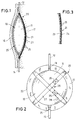
- an implant 10 is shown, which is an artificial bladder.
- the implant 10 consists of a container 11 made of elastic plastic.
- This container, the front view (Fig. 2) is round, axially be squeezed together. At the end of the axial pressing force however, the original container shape forms again, in the container is expanded.
- a catheter coming from a kidney opens into the container 11 12, which contains a check valve 13. From the bottom of the container 11, a urethral catheter 14 leads out Check valve 15 contains.
- the container 11 is between the Skin 16 and the patient's muscle tissue 17 implanted. This can the container 11th by external pressure squeeze to release liquid inside the Push in urethral catheter 14. Then the Container 11 strives to expand again. This is how he works a suction effect to suck urine out of the kidney.
- the implant 10 can be replaced in the implant holder 20 used.
- the implant holder 20 has a shielding wall 21 that separates the implant 10 from the muscle tissue 17.
- the Shielding wall 21 is so large that it is the horizontal projection of the implant 10 completely covered and still towering over how Fig. 2 shows so that the shield with a protruding Edge 22 protrudes beyond the contour of implant 10.
- the shielding wall 21 faces the implant 10 Inside a film layer 23 made of smooth silicone film.
- This film layer has a thickness of 1 - 1.5 mm.
- Velor layer 24 made of fabric-friendly fiber material, preferably made of Dakron velor. The hairs of this Velor layer 24 protrude outwards and form it Fiber material 25 for the growth of muscle tissue 17.
- a bracket 26 is on the edge 22 of the shielding wall 21 attached that the implant 10 on the inside of the Shielding wall 21 holds.
- This bracket 26 consists of two cross-shaped bandages 27, 28, each with a lock 29 are provided.
- the bandages 27, 28 consist of relatively narrow bands of material on which cells are not can grow well.
- the material of the implant 10 is the same chosen that it is not possible with the body tissue connects.
- bracket 26 During one side of the implant through the shielding wall the other side of the implant is completely covered free, with a small part (less than 10%) is covered only by the bracket 26.
- a small part (less than 10%) is covered only by the bracket 26.
- the bracket on the shielding wall 21 there is the possibility of holding the bracket on the shielding wall 21 to be provided so that the surface facing away from the shielding wall of the implant is completely exposed.
- the implant 10 is an artificial bladder that starts with Connected to catheters 12, 14 should be the catheter connection be detachable so that the catheters can remain implanted, while the bladder is being replaced.
Landscapes
- Health & Medical Sciences (AREA)
- General Health & Medical Sciences (AREA)
- Public Health (AREA)
- Transplantation (AREA)
- Cardiology (AREA)
- Biomedical Technology (AREA)
- Heart & Thoracic Surgery (AREA)
- Vascular Medicine (AREA)
- Life Sciences & Earth Sciences (AREA)
- Oral & Maxillofacial Surgery (AREA)
- Animal Behavior & Ethology (AREA)
- Engineering & Computer Science (AREA)
- Veterinary Medicine (AREA)
- Urology & Nephrology (AREA)
- Gastroenterology & Hepatology (AREA)
- Pulmonology (AREA)
- Prostheses (AREA)
- Media Introduction/Drainage Providing Device (AREA)
- Electrotherapy Devices (AREA)
- Materials For Medical Uses (AREA)
Abstract
Description
- Fig. 1
- eine Seitenansicht einer künstlichen Harnblase, die in den Körper implantiert ist,
- Fig. 2
- eine Frontansicht der künstlichen Harnblase, die in den Implantathalter eingesetzt ist, und
- Fig. 3
- einen Querschnitt durch das Material der Abschirmwand des Implantathalters.
Claims (4)
- Implantathalter für Körperimplantate, mit einer anwachsenden Abschirmwand (21), die an einer Seite gewebefreundliches Fasermaterial (25) zum Anwachsen körpereigener Zellen und an der gegenüberliegenden Seite eine Anlagefläche für das Implantat (10) aufweist, und daß eine Halterung (26) vorgesehen ist, die geeignet ist, ein Implantat (10) an der Anlagefläche festzuhalten.
- Implantathalter nach Anspruch 1, dadurch gekennzeichnet, daß die Abschirmwand (21) die horizontale Projektion des Implantats vollständig bedeckt.
- Implantathalter nach Anspruch 1 oder 2, dadurch gekennzeichnet, daß die Halterung (26) aus mindestens einer an der Abschirmwand (21) befestigten Bandage (27,28) besteht.
- Implantathalter nach einem der Ansprüche 1-3, dadurch gekennzeichnet, daß die Abschirmwand (21) aus einer Folie (23) und einer Veloursschicht (24) besteht.
Applications Claiming Priority (2)
| Application Number | Priority Date | Filing Date | Title |
|---|---|---|---|
| DE19831699 | 1998-07-15 | ||
| DE19831699A DE19831699C1 (de) | 1998-07-15 | 1998-07-15 | Implantathalter |
Publications (2)
| Publication Number | Publication Date |
|---|---|
| EP0972496A2 true EP0972496A2 (de) | 2000-01-19 |
| EP0972496A3 EP0972496A3 (de) | 2000-10-25 |
Family
ID=7874100
Family Applications (1)
| Application Number | Title | Priority Date | Filing Date |
|---|---|---|---|
| EP99112691A Withdrawn EP0972496A3 (de) | 1998-07-15 | 1999-07-02 | Implantathalter |
Country Status (4)
| Country | Link |
|---|---|
| US (1) | US6350285B2 (de) |
| EP (1) | EP0972496A3 (de) |
| JP (1) | JP2000126211A (de) |
| DE (1) | DE19831699C1 (de) |
Cited By (2)
| Publication number | Priority date | Publication date | Assignee | Title |
|---|---|---|---|---|
| ITMI20121804A1 (it) * | 2012-10-24 | 2014-04-25 | Gianni Cancarini | Protesi vescicale |
| EP2566414B1 (de) * | 2010-05-06 | 2017-08-02 | Primed Halberstadt Medizintechnik GmbH | Harnblasenprothese für die subkutane implantation |
Families Citing this family (9)
| Publication number | Priority date | Publication date | Assignee | Title |
|---|---|---|---|---|
| DE10037504B4 (de) * | 2000-08-01 | 2006-08-10 | KRUG, Hans-Jürgen | Künstliche Gelenkvorrichtung |
| US20040116969A1 (en) * | 2002-08-26 | 2004-06-17 | Owen James M. | Pulse detection using patient physiological signals |
| US8007531B2 (en) * | 2004-08-06 | 2011-08-30 | Frank Robert E | Implantable prosthesis for positioning and supporting a breast implant |
| US7476249B2 (en) | 2004-08-06 | 2009-01-13 | Frank Robert E | Implantable prosthesis for positioning and supporting a breast implant |
| US7923526B2 (en) * | 2004-09-01 | 2011-04-12 | Eastman Chemical Company | Sulfopolyesters having improved clarity in water-dispersible formulations and products made therefrom |
| US7833284B2 (en) * | 2006-06-28 | 2010-11-16 | The Cleveland Clinic Foundation | Anti-adhesion membrane |
| US8690900B2 (en) * | 2008-07-21 | 2014-04-08 | The Cleveland Clinic Foundation | Apparatus and method for connecting two elongate body tissues |
| EP2475309A4 (de) | 2009-09-08 | 2015-07-29 | Atrium Medical Corp | Herniapflaster |
| CN115192251A (zh) * | 2022-07-28 | 2022-10-18 | 复旦大学附属中山医院 | 一种异位人工膀胱装置 |
Citations (1)
| Publication number | Priority date | Publication date | Assignee | Title |
|---|---|---|---|---|
| DE2760437C2 (de) | 1976-04-05 | 1990-03-22 | Agence Nationale De Valorisation De La Recherche (Anvar), Paris, Fr |
Family Cites Families (16)
| Publication number | Priority date | Publication date | Assignee | Title |
|---|---|---|---|---|
| US3489647A (en) * | 1964-05-06 | 1970-01-13 | Dow Corning | Artificial organ for membrane dialysis of biological fluids |
| US3988411A (en) * | 1974-02-11 | 1976-10-26 | American Cyanamid Company | Spinning and shaping poly-(N-acetyl-D-glucosamine) |
| JPS63119749A (ja) * | 1985-11-27 | 1988-05-24 | 川原 春幸 | 多重毛管構造を有するインプラント部材 |
| US4627429A (en) * | 1986-02-28 | 1986-12-09 | American Home Products Corporation | Storage-stable transdermal adhesive patch |
| US4969902A (en) * | 1987-02-20 | 1990-11-13 | Biagio Ravo | Implantable device |
| SU1604377A1 (ru) * | 1987-02-23 | 1990-11-07 | Благовещенский государственный медицинский институт | Искусственный перикард |
| DE8810783U1 (de) * | 1988-06-06 | 1988-10-20 | Mecron Medizinische Produkte Gmbh, 1000 Berlin | Schraubpfanne als Teil einer Hüftgelenksprothese |
| US5475052A (en) * | 1988-11-21 | 1995-12-12 | Collagen Corporation | Collagen-synthetic polymer matrices prepared using a multiple step reaction |
| US5314471A (en) * | 1991-07-24 | 1994-05-24 | Baxter International Inc. | Tissue inplant systems and methods for sustaining viable high cell densities within a host |
| JPH06506366A (ja) * | 1990-12-06 | 1994-07-21 | ダブリュ.エル.ゴア アンド アソシエーツ,インコーポレイティド | 植設可能な生体吸収性部材 |
| US5356429A (en) * | 1991-05-16 | 1994-10-18 | Seare William J Jr | Body pocket maintenance prosthesis |
| AU688776B2 (en) * | 1993-06-23 | 1998-03-19 | Brown University Research Foundation | Method and apparatus for sealing implantable, membrane encapsulation devices |
| JP2580836Y2 (ja) * | 1993-12-16 | 1998-09-17 | 繁 風間 | 心臓翻転具 |
| US5824050A (en) * | 1996-12-03 | 1998-10-20 | Atrium Medical Corporation | Prosthesis with in-wall modulation |
| US6045497A (en) * | 1997-01-02 | 2000-04-04 | Myocor, Inc. | Heart wall tension reduction apparatus and method |
| US6120539A (en) * | 1997-05-01 | 2000-09-19 | C. R. Bard Inc. | Prosthetic repair fabric |
-
1998
- 1998-07-15 DE DE19831699A patent/DE19831699C1/de not_active Expired - Fee Related
-
1999
- 1999-07-02 EP EP99112691A patent/EP0972496A3/de not_active Withdrawn
- 1999-07-09 US US09/350,285 patent/US6350285B2/en not_active Expired - Fee Related
- 1999-07-14 JP JP11200365A patent/JP2000126211A/ja active Pending
Patent Citations (1)
| Publication number | Priority date | Publication date | Assignee | Title |
|---|---|---|---|---|
| DE2760437C2 (de) | 1976-04-05 | 1990-03-22 | Agence Nationale De Valorisation De La Recherche (Anvar), Paris, Fr |
Cited By (2)
| Publication number | Priority date | Publication date | Assignee | Title |
|---|---|---|---|---|
| EP2566414B1 (de) * | 2010-05-06 | 2017-08-02 | Primed Halberstadt Medizintechnik GmbH | Harnblasenprothese für die subkutane implantation |
| ITMI20121804A1 (it) * | 2012-10-24 | 2014-04-25 | Gianni Cancarini | Protesi vescicale |
Also Published As
| Publication number | Publication date |
|---|---|
| DE19831699C1 (de) | 2000-04-27 |
| US20010004714A1 (en) | 2001-06-21 |
| JP2000126211A (ja) | 2000-05-09 |
| US6350285B2 (en) | 2002-02-26 |
| EP0972496A3 (de) | 2000-10-25 |
Similar Documents
| Publication | Publication Date | Title |
|---|---|---|
| DE3141459C2 (de) | ||
| DE69120949T2 (de) | Glaukomimplantat | |
| DE69309051T2 (de) | Vorrichtung zum strecken von lebendem gewebe | |
| DE60316341T2 (de) | Implantierbare medizinische vorrichtung zum verbesserten einsetzen | |
| DE69312532T2 (de) | Prothese für die Plattfusskorrektur | |
| DE69502497T2 (de) | Sklerotomie-implantat | |
| DE2925089A1 (de) | Gelenkprothese, insbesondere kuenstliches oberschenkelhueftgelenk | |
| DE4400188A1 (de) | Implantat für ein Trommelfell-Loch und Unterseitenkratzer für ein Trommelfell | |
| EP1529501A1 (de) | Subkutanes, intramuskuläres Lager für ein starres transkutanes Implantat | |
| CH684307A5 (de) | Verlängerung von linearem und rohrförmigem Gewebe. | |
| DE69305863T2 (de) | Expansionsvorrichtung zur oralen Rekonstruktion | |
| DE69117541T2 (de) | Implantat mit durchgangsöffnung | |
| DE2908898A1 (de) | Prothesengelenk | |
| DE2007355A1 (de) | Haarimplantate | |
| DE2638134A1 (de) | Fingergelenk-implantat | |
| EP0393425A1 (de) | Einzementierbares Oberschenkelteil einer Hüftgelenk-Endoprothese | |
| DE2440103A1 (de) | Operativ implantierbare gelenkprothese | |
| DE2951181A1 (de) | Schutzvorrichtung fuer eine implantierte prothese | |
| DE19831699C1 (de) | Implantathalter | |
| DE3146182A1 (de) | "elektrode fuer herzschrittmacher" | |
| DE2258223C3 (de) | Chirurgisch einsetzbare Einrichtung für eine Bruchkorrektur | |
| DE68901887T2 (de) | Gewebedilatatoren. | |
| DE60018566T2 (de) | Intraurethrale Vorrichtung | |
| DE2705234A1 (de) | Keratoprothese | |
| EP0005275A1 (de) | Brustprothese |
Legal Events
| Date | Code | Title | Description |
|---|---|---|---|
| PUAI | Public reference made under article 153(3) epc to a published international application that has entered the european phase |
Free format text: ORIGINAL CODE: 0009012 |
|
| AK | Designated contracting states |
Kind code of ref document: A2 Designated state(s): AT BE CH CY DE DK ES FI FR GB GR IE IT LI LU MC NL PT SE |
|
| AX | Request for extension of the european patent |
Free format text: AL;LT;LV;MK;RO;SI |
|
| PUAL | Search report despatched |
Free format text: ORIGINAL CODE: 0009013 |
|
| AK | Designated contracting states |
Kind code of ref document: A3 Designated state(s): AT BE CH CY DE DK ES FI FR GB GR IE IT LI LU MC NL PT SE |
|
| AX | Request for extension of the european patent |
Free format text: AL;LT;LV;MK;RO;SI |
|
| 17P | Request for examination filed |
Effective date: 20010110 |
|
| AKX | Designation fees paid |
Free format text: AT BE CH CY DE DK ES FI FR GB GR IE IT LI LU MC NL PT SE |
|
| STAA | Information on the status of an ep patent application or granted ep patent |
Free format text: STATUS: THE APPLICATION IS DEEMED TO BE WITHDRAWN |
|
| 18D | Application deemed to be withdrawn |
Effective date: 20030201 |