EP0972683A1 - Verfahren und Vorrichtung zum Falten eines aufblasbaren Luftsacks - Google Patents
Verfahren und Vorrichtung zum Falten eines aufblasbaren Luftsacks Download PDFInfo
- Publication number
- EP0972683A1 EP0972683A1 EP99113733A EP99113733A EP0972683A1 EP 0972683 A1 EP0972683 A1 EP 0972683A1 EP 99113733 A EP99113733 A EP 99113733A EP 99113733 A EP99113733 A EP 99113733A EP 0972683 A1 EP0972683 A1 EP 0972683A1
- Authority
- EP
- European Patent Office
- Prior art keywords
- airbag
- carrier
- sleeve
- stamp
- cover
- Prior art date
- Legal status (The legal status is an assumption and is not a legal conclusion. Google has not performed a legal analysis and makes no representation as to the accuracy of the status listed.)
- Granted
Links
Images




Classifications
-
- B—PERFORMING OPERATIONS; TRANSPORTING
- B60—VEHICLES IN GENERAL
- B60R—VEHICLES, VEHICLE FITTINGS, OR VEHICLE PARTS, NOT OTHERWISE PROVIDED FOR
- B60R21/00—Arrangements or fittings on vehicles for protecting or preventing injuries to occupants or pedestrians in case of accidents or other traffic risks
- B60R21/02—Occupant safety arrangements or fittings, e.g. crash pads
- B60R21/16—Inflatable occupant restraints or confinements designed to inflate upon impact or impending impact, e.g. air bags
- B60R21/23—Inflatable members
- B60R21/237—Inflatable members characterised by the way they are folded
-
- B—PERFORMING OPERATIONS; TRANSPORTING
- B60—VEHICLES IN GENERAL
- B60R—VEHICLES, VEHICLE FITTINGS, OR VEHICLE PARTS, NOT OTHERWISE PROVIDED FOR
- B60R21/00—Arrangements or fittings on vehicles for protecting or preventing injuries to occupants or pedestrians in case of accidents or other traffic risks
- B60R21/02—Occupant safety arrangements or fittings, e.g. crash pads
- B60R21/16—Inflatable occupant restraints or confinements designed to inflate upon impact or impending impact, e.g. air bags
- B60R21/23—Inflatable members
- B60R21/237—Inflatable members characterised by the way they are folded
- B60R2021/2375—Folding devices
-
- B—PERFORMING OPERATIONS; TRANSPORTING
- B60—VEHICLES IN GENERAL
- B60R—VEHICLES, VEHICLE FITTINGS, OR VEHICLE PARTS, NOT OTHERWISE PROVIDED FOR
- B60R21/00—Arrangements or fittings on vehicles for protecting or preventing injuries to occupants or pedestrians in case of accidents or other traffic risks
- B60R21/02—Occupant safety arrangements or fittings, e.g. crash pads
- B60R21/16—Inflatable occupant restraints or confinements designed to inflate upon impact or impending impact, e.g. air bags
- B60R21/20—Arrangements for storing inflatable members in their non-use or deflated condition; Arrangement or mounting of air bag modules or components
- B60R21/217—Inflation fluid source retainers, e.g. reaction canisters; Connection of bags, covers, diffusers or inflation fluid sources therewith or together
-
- Y—GENERAL TAGGING OF NEW TECHNOLOGICAL DEVELOPMENTS; GENERAL TAGGING OF CROSS-SECTIONAL TECHNOLOGIES SPANNING OVER SEVERAL SECTIONS OF THE IPC; TECHNICAL SUBJECTS COVERED BY FORMER USPC CROSS-REFERENCE ART COLLECTIONS [XRACs] AND DIGESTS
- Y10—TECHNICAL SUBJECTS COVERED BY FORMER USPC
- Y10S—TECHNICAL SUBJECTS COVERED BY FORMER USPC CROSS-REFERENCE ART COLLECTIONS [XRACs] AND DIGESTS
- Y10S493/00—Manufacturing container or tube from paper; or other manufacturing from a sheet or web
- Y10S493/94—Bellows
Definitions
- the invention relates to a method and a device for folding an inflatable airbag for motor vehicles.
- Such methods and devices are used to inflatable Fold airbag to a size that allows the folded one Airbag as part of an airbag module, for example as a driver, To mount the passenger or side airbag on a vehicle.
- the airbag must be folded so that it is in one when inflated Crash case as quickly as possible and without damaging the airbag cover can unfold.
- a to be folded Air bag is attached to a carrier with its open end, that a preferably substantially cylindrical stamp through an opening in the carrier into the airbag against the closed End of the airbag is advanced, and that the carrier and the Stamps are inserted into a sleeve, the air bag irregular is squeezed.
- the folding of the airbag does not have to be within one Room with a given height.
- the airbag or the airbag envelope not necessarily in a defined and predictable Folded together, but squeezed or crumpled up, so that a ring-shaped, but otherwise arbitrary or "chaotic" fold, also known as a scrunch fold, which nevertheless allows the airbag to unfold quickly and optimally radial direction allows.
- the invention makes it possible to compress of the airbag to achieve a low undercut folding, which allows the airbag to unfold radially, reducing the risk of injury is minimized for the vehicle occupants.
- the airbag pressed into a cover of an airbag module preferably the cover has a base element and one connected to the base element Wall section includes.
- an airbag module ready for assembly is done in this way considerably accelerated, since after the folding process compressed air bag already in its through the e.g. in shape a cover provided cover is formed housing, in which it is mounted on the vehicle.
- the fact that the airbag in can be folded directly into the cover in a single step can, the entire process is much faster, mechanically easier and consequently considerably more economical. If the airbag at the beginning of the Folding process is pre-assembled on a base plate, then the airbag can thus be folded directly into the cover through the base plate, that the base plate is then connected to the cover and thus the airbag module with the exception of a gas generator ready for installation is present.
- the airbag is placed around the sleeve before the carrier is inserted into the sleeve Stamps are preferably pressed together manually.
- the squeeze is preferably done manually, but can also e.g. by means of automated sliding elements distributed around the stamp become.
- the carrier before the insertion of the carrier into the sleeve of the airbag preferably manually stuffed the sleeve and / or dropped down into the sleeve.
- the airbag is plugged into the Fold space or fold channel around the stamp manually.
- the stamp advanced against the closed end of the airbag until one or several, preferably band-like, arranged in the interior of the airbag Fasteners that use the closed end of the airbag connect the open end of the airbag or to the carrier, tensioned are.
- the problem (task) on which the invention is based is solved also by the features of the folding device Claim 9 and in particular in that a carrier to which a folding airbag is attachable at its open end, a preferred essentially cylindrical stamp formed by a in the carrier Opening into the airbag against the closed end of the Air bags can be advanced, and a sleeve is provided, in which the Carrier and the stamp can be introduced, the carrier, the stamp and / or the sleeve for compressing the airbag relative to one another are movable.
- the invention makes it simple and versatile Folding device created which a room with variable height provides and with which the airbag or the airbag cover on a any height can be compressed without the Gas generator must be included.
- a carrier element the carrier releasably with a preferably a base plate and / or a preferably a ring-shaped holding element assembly Airbag module connected, preferably with respect to the base plate
- Airbag module connected, preferably with respect to the base plate
- the carrier for attaching the airbag to be folded is through the base plate, the holding element and the carrier element are formed, so that then, when the connection between solved the support member and the base plate or the holding element an essential assembly of the airbag module is completed.
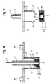
- 1a to 1f is an embodiment of an inventive Folding device shown to carry out an inventive Folding process is provided.
- the folding device shown in FIGS. 1a to 1f comprises according to FIG. 1a a horizontal worktop 30 in which a recess is provided is.
- a sleeve 24 is arranged below the worktop 30, whose inner wall is flush with the recess in the worktop 30 delimiting border area and their cross-sectional area of those of the airbag 10 having its final package size corresponds.
- a cover 25 in the form of a cover cap an airbag module, which has a base element 26 and a Wall section 27 integrally connected to the base element 26 includes, which runs parallel to the sleeve wall.
- the free inner cross-sectional area the cover 25 corresponds to that of the sleeve 24.
- Bending elements 32 are provided between the sleeve 24 and the cover 25, which are cuboid and rotatably mounted.
- the Purpose of the bending elements 32 will be explained below in the explanation of folding method according to the invention described.
- a support element 12 which is attached to its underside a base plate 14 and an annular, hereinafter designated as a retaining ring 16 carries an airbag module.
- the carrier element forms 12 a carrier on which an airbag 10 to be folded with its open end 11, which is also referred to as the mouthpiece of the airbag 10 is attached.
- the airbag 10 is with its area delimiting the mouthpiece Airbag envelope arranged around a circular opening 20 which in the base plate 14 and in the retaining ring 16 is formed.
- the cross-sectional area of the base plate 14 is dimensioned such that the Base plate 14 fits snugly into the sleeve 24 and the cover 25 can be.
- a cylindrical punch 18 is relative to the carrier in the vertical direction movable and through the tubular support member 12 and the opening 20 provided in the base plate 14 and the retaining ring 16 displaceable into the airbag 10.
- the diameter of the stamp 18 and the diameter of the opening 20 correspond at least substantially to the diameter of an Ready-to-install airbag module provided gas generator, not shown.
- the closed end 22 of the airbag 10 to be folded is over several, preferably two or four band-like connecting elements 23 either with the area of the airbag envelope forming the mouthpiece of the airbag 10 or connected to the base plate 14 or the retaining ring 16 in such a way that the closed end 22 or an area of the closed End 22 of the airbag 10 below the opening 20, d. H. on a arranged by the longitudinal axis of the stamp 18 folding axis is.
- the length of the connecting elements 23 is chosen such that the airbag envelope 10 around its closed end 22 to below the depending on the height 22 defined by the closed end can.
- a folding method according to the invention which with that explained above Folding device is feasible, is based on the following 1a-1f described.
- the airbag 10 to be folded is first described in the above Way on the base plate 14 or on the retaining ring 16 with his open end 11 attached so that the airbag cover according to FIG. 1a of the Base plate 14 or the retaining ring 16 hangs down. At the beginning of the folding process the airbag 10 is consequently connected to the base plate 14.
- the stamp 18 is then inserted into and against the airbag 10 pushed the closed end 22 until the connecting elements 23 are tensioned are, as shown in Fig. 1b. Before, after or with the feed movement of the stamp 18 into the airbag 10 becomes the carrier element 12 lowered.
- the airbag cover 10 can be inserted into the base plate 14 Sleeve 24 compressed around the punch 18 by sliding elements 28 become. In a preferred variant, the compression takes place the airbag cover 10 in the direction of the stamp, however Hand. In this way, areas of the drooping airbag envelope 10, according to FIG. 1b, beyond the circumference of the base plate 14 protrude outwards, pushed under the base plate 14.
- the sliding elements 28 are defined by the longitudinal axis of the punch Folding axis arranged around and in the through the worktop 30 defined level movable.
- Fig. 1c shows that the sliding elements 28 press the airbag cover 10 in the direction of the stamp 18, that the entire airbag cover 10 is brought under the base plate 14 becomes.
- the airbag cover 10 by hand in the pressed together shown in Fig. 1b and Fig. 1c Brought condition.
- the stamp 18 projects further into the sleeve 24 than in FIG. 1c. In principle, however, the stamp 18 can be pressed before and during the compression the airbag cover 10 also less than or further than protrude into the sleeve as shown.
- the Airbag sleeve 10 Before the carrier element 12 is lowered further, the Airbag sleeve 10 also stuffed into sleeve 24, preferably this also done manually.
- the airbag cover 10 is not only here by hand horizontally in the direction of the stamp 18, but also also pressed vertically down into the interior of the sleeve 24.
- the bending elements 32 attached to the sleeve 24 are in accordance with 1c already during the compression of the airbag cover 10 in brought an insertion position in which they have an inner long side Form an extension of the inner wall of the sleeve and one with an outside region of the wall section 27 which is designed to be elastically deformable bend the cover 25 outwards. In this way, the insertion opening the cover 25 expanded.
- the distance between the open end 11 and the closed end 22 of the airbag 10 remains at least substantially constant during this time.
- the support element 12 is lowered further and onto the base element 26 too moved.
- the ring around the stamp 18th air bag envelope 10 compressed around, d. H. in the cover 25 pressed in until the base plate 14 and the retaining ring 16 1e are within the cover 25 and the desired Pack height is reached.
- the air bag 10 compressed to its final package size 1f the housing is ready for installation within it of the airbag module-forming cover 25, wherein the airbag 10 ring-shaped around one remaining after pulling out the stamp 18 central free space is compressed around, into which one is not shown gas generator of the airbag module can be used.
- the stamp 18 is dimensioned such that the free space in the airbag module has the dimensions required for the gas generator.
- the invention makes a method that can be carried out quickly and easily created for folding an air bag, which on the one hand ensured it is that the airbag cover ring-shaped and without undercuts or is compressed at least with little undercuts, in the event of a crash to enable radial unfolding, but on the other hand within no defined and predictable wrinkling occurs in the folding area, but according to a "chaotic" folding process the exact course of the Airbag cover 10 is left to chance as it is entwined by the Lines in Figs. 1c - 1f is indicated.
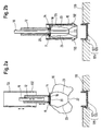
- the stamp 18 with the interposition of the closed end 22 of the airbag 10 in the stop brought to the bottom member 126 of the cover 125 before that Carrier element 12 is lowered further to the airbag 10 within of the annular folding space to its final pack size.
- Fig. 2c the stamp 18 is still from the bottom element 126 spaced position shown.
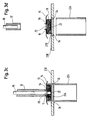
- FIGS. 3a-3d The airbag 10 is not folded in an airbag module cover compressed to its final pack size. Instead, a bottom element 226 is provided according to FIG. 3a, which is part of a worktop 230.
- the stamp 18 first arrives with the interposition of the closed one End 22 of the airbag 10 in abutment on the base element 226, whereupon, when the support element 12 is lowered further, the airbag 10 inside the annular folding space to its final package size is compressed, as shown in Fig. 3c.
Landscapes
- Engineering & Computer Science (AREA)
- Mechanical Engineering (AREA)
- Air Bags (AREA)
Abstract
Description
- Fig. 1a - 1f
- eine Seitenansicht einer Ausführungsform einer erfindungsgemäßen Faltvorrichtung in verschiedenen Phasen eines erfindungsgemäßen Faltverfahrens,
- Fig. 2a - 2d
- eine Seitenansicht einer weiteren Ausführungsform einer erfindungsgemäßen Faltvorrichtung in verschiedenen Phasen eines weiteren erfindungsgemäßen Faltverfahrens, und
- Fig. 3a - 3d
- eine Seitenansicht einer weiteren Ausführungsform einer erfindungsgemäßen Faltvorrichtung in verschiedenen Phasen eines weiteren erfindungsgemäßen Faltverfahrens.
- 10
- Luftsack, Luftsackhülle
- 11
- offenes Ende des Luftsacks
- 12
- Trägerelement
- 14
- Basisplatte
- 16
- Haltering
- 18
- Stempel
- 20
- Öffnung
- 22
- geschlossenes Ende des Luftsacks
- 23
- Verbindungselemente
- 24, 124, 224
- Hülse
- 25, 125
- Abdeckung
- 26, 126, 226
- Bodenelement
- 27, 127
- Wandabschnitt
- 28
- Schiebeelemente
- 30, 130, 230
- Arbeitsplatte
- 32, 132
- Biegeelemente
- 34
- Aussparungen
Claims (14)
- Verfahren zum Falten eines aufblasbaren Luftsacks (10) für Kraftfahrzeuge, welches die Schritte umfaßt,daß ein zu faltender Luftsack (10) mit seinem offenen Ende (11) an einem Träger (12, 14, 16) befestigt wird,daß ein bevorzugt im wesentlichen zylindrischer Stempel (18) durch eine Öffnung (20) im Träger (12, 14, 16) hindurch in den Luftsack (10) hinein gegen das geschlossene Ende (22) des Luftsacks (10) vorgeschoben wird, unddaß der Träger (12, 14, 16) und der Stempel (18) in eine Hülse (24, 124, 224) eingebracht werden, wobei der Luftsack (10) unregelmäßig zusammengedrückt wird.
- Verfahren nach Anspruch 1,
dadurch gekennzeichnet,daß ein von dem Träger (12, 14, 16), dem Stempel (18), der Hülseninnenwand und einem Bodenelement (26, 126, 226) begrenzter Raum verkleinert wird, bis der Luftsack (10) auf seine endgültige Packungsgröße zusammengedrückt ist. - Verfahren nach Anspruch 1 oder 2,
dadurch gekennzeichnet,daß der Luftsack (10) in eine Abdeckung (25, 125) eines Luftsackmoduls gedrückt wird, wobei bevorzugt die Abdeckung (25, 125) ein Bodenelement (26, 126) und einen mit dem Bodenelement (26, 126) verbundenen Wandabschnitt (27, 127) umfaßt. - Verfahren nach zumindest einem der vorhergehenden Ansprüche,
dadurch gekennzeichnet,daß der Luftsack (10) mit seinem offenen Ende (11) an einer bevorzugt eine Basisplatte (14) und/oder ein vorzugsweise ringförmiges Halteelement (16) umfassenden Baugruppe eines Luftsackmoduls befestigt wird, wobei eine Verbindung zwischen der Baugruppe und einem Trägerelement (12) des Trägers gelöst wird, nachdem der Luftsack (10) auf seine endgültige Packungsgröße zusammengedrückt ist, und/oderdaß ein bevorzugt elastisch verformbarer Wandabschnitt (27, 127) einer Abdeckung (25, 125) für den zusammengedrückten Luftsack (10) aufgeweitet wird, bevor der Träger (12, 14, 16) in die Abdeckung (25, 125) eingeführt wird, und/oderdaß der Träger (12, 14, 16), insbesondere eine Basisplatte (14) des Trägers (12, 14, 16), im in eine Abdeckung (25, 125) eingeführten Zustand mit der Abdeckung (25, 125) bevorzugt fest verbunden ist. - Verfahren nach zumindest einem der vorhergehenden Ansprüche,
dadurch gekennzeichnet,daß der Luftsack (10) vor dem Einbringen des Trägers (12, 14, 16) in die Hülse (24) um den Stempel herum bevorzugt manuell zusammengedrückt wird. - Verfahren nach zumindest einem der vorhergehenden Ansprüche,
dadurch gekennzeichnet,daß vor dem Einführen des Trägers (12, 14, 16) in die Hülse (24) der Luftsack (10) bevorzugt manuell in die Hülse (24) gestopft und/oder in die Hülse (24) nach unten fallengelassen wird. - Verfahren nach zumindest einem der vorhergehenden Ansprüche,
dadurch gekennzeichnet,daß der Stempel (18) gegen das geschlossene Ende (22) des Luftsacks (10) vorgeschoben wird, bis ein oder mehrere im Inneren des Luftsacks (10) angeordnete, bevorzugt bandartige Verbindungselemente (23), welche das geschlossene Ende (22) des Luftsacks (10) mit dessen offenem Ende (11) oder mit dem Träger (12, 14, 16) verbinden, gespannt sind, und/oderdaß vor dem Zusammendrücken des Luftsacks (10) auf seine endgültige Packungsgröße der Stempel (18) in eine Endstellung in der Nähe eines Bodenelementes (26, 126, 226) und bevorzugt derart nahe an das Bodenelement (26, 126, 226) heran bewegt wird, daß ein Bereich des geschlossenen Endes (22) des Luftsacks (10) gegen das Bodenelement (26, 126, 226) gedrückt wird. - Verfahren nach zumindest einem der vorhergehenden Ansprüche,
dadurch gekennzeichnet,daß nach dem Einbringen des Trägers (12, 14, 16) und des Stempels (18) in die Hülse (124) zunächst die dadurch gebildete Einheit als Ganzes in Richtung eines feststehend angeordneten Bodenelementes (126) bewegt und anschließend der Träger (12, 14, 16) relativ zur Hülse (124) auf das Bodenelement (126) zu bewegt wird, und/oderdaß nach dem Einbringen des Trägers (12, 14, 16) und des Stempels (18) in die Hülse (224) die dadurch gebildete Einheit als Ganzes in Richtung eines feststehend angeordneten Bodenelementes (226) bewegt wird, wobei die Hülse (224) über das Bodenelement (226) geschoben wird, bis der Abstand zwischen dem Träger (12, 14, 16) und dem Bodenelement (226) der endgültigen Packungshöhe des zusammengedrückten Luftsacks (10) entspricht. - Vorrichtung zum Falten eines aufblasbaren Luftsacks für Kraftfahrzeuge, insbesondere zur Durchführung eines Verfahrens nach zumindest einem der vorhergehenden Ansprüche, mit einem Träger (12, 14, 16), an dem ein zu faltender Luftsack (10) mit seinem offenen Ende (11) befestigbar ist, einem bevorzugt im wesentlichen zylindrischen Stempel (18), der durch eine im Träger (12, 14, 16) ausgebildete Öffnung (20) in den Luftsack (10) hinein gegen das geschlossene Ende (22) des Luftsacks (10) vorschiebbar ist, und einer Hülse (24, 124, 224), in die der Träger (12, 14, 16) und der Stempel (18) einbringbar sind, wobei der Träger (12, 14, 16), der Stempel (18) und/oder die Hülse (24, 124, 224) zum Zusammendrücken des Luftsacks (10) relativ zueinander bewegbar sind.
- Vorrichtung nach Anspruch 9,
dadurch gekennzeichnet,daß der Träger (12, 14, 16), der Stempel (18), die Hülse (24, 124, 224) und/oder ein Bodenelement (26, 126, 226) relativ zueinander derart bewegbar sind, daß ein von ihnen begrenzter Raum verkleinerbar ist. - Vorrichtung nach Anspruch 9 oder 10,
dadurch gekennzeichnet,daß ein Trägerelement (12) des Trägers lösbar mit einer bevorzugt eine Basisplatte (14) und/oder ein vorzugsweise ringförmiges Halteelement (16) umfassenden Baugruppe eines Luftsackmoduls verbunden ist, wobei bevorzugt die Basisplatte (14) hinsichtlich Form und Größe der freien inneren Querschnittsfläche der Hülse (24, 124) entspricht. - Vorrichtung nach zumindest einem der Ansprüche 9 bis 11,
dadurch gekennzeichnet,daß unterhalb der Hülse (24, 124) eine Abdeckung (25, 125) für den zusammengedrückten Luftsack (10) angeordnet ist, wobei bevorzugt die Abdeckung (25, 125) ein Bodenelement (26, 126) und einen mit dem Bodenelement (26, 126) verbundenen Wandabschnitt (27, 127) umfaßt, und/oderdaß bevorzugt an der Hülse (24, 124) angebrachte Biegeelemente (32, 132) zwischen die Hülse (24, 124) und einen bevorzugt elastisch vefformbaren Wandabschnitt (27, 127) einer Abdeckung (25, 125) für den zusammengedrückten Luftsack bringbar sind, wobei die Biegeelemente (32, 132) zum Einführen des Trägers (12, 14, 16), insbesondere einer eine Basisplatte (14) und/oder ein vorzugsweise ringförmiges Halteelement (16) umfassenden Baugruppe, in die Abdeckung (25, 125) in eine Einführstellung bringbar sind, in der sie den Wandabschnitt (27, 127) der Abdeckung (25, 125) aufweiten, und/oderdaß der Querschnitt des Trägers (12, 14, 16), insbesondere einer Basisplatte (14) eines Luftsackmoduls, hinsichtlich Form und Größe zumindest im wesentlichen der freien inneren Querschnittsfläche der Hülse (24, 124, 224) und/oder einer Abdeckung (25, 125) für den zusammengedrückten Luftsack (10) und bevorzugt demjenigen des endgültig zusammengedrückten Luftsacks (10) entspricht. - Vorrichtung nach zumindest einem der Ansprüche 9 bis 12,
dadurch gekennzeichnet,daß der Querschnitt des Stempels (18) hinsichtlich Form und Größe zumindest im wesentlichen demjenigen eines Gasgenerators für den Luftsack (10) entspricht. - Vorrichtung nach zumindest einem der Ansprüche 9 bis 13,
dadurch gekennzeichnet,daß die Hülse (24) und ein bevorzugt unterhalb der Hülse (24) angeordnetes Bodenelement (26) feststehend angeordnet sind, wobei der Träger (12, 14, 16) und der Stempel (18) in die Hülse (24) einführbar und in Richtung des Bodenelementes (26) bewegbar sind, und/oderdaß lediglich ein Bodenelement (126) feststehend angeordnet ist, wobei der Träger (12, 14, 16) und der Stempel (18) in die Hülse (124) einführbar und zusammen mit der Hülse (124) in Richtung des Bodenelementes (126) bewegbar sind, und/oderdaß lediglich ein Bodenelement (226) feststehend angeordnet und die Hülse (224) über das Bodenelement (226) schiebbar ist, wobei der Träger (12, 14, 16) und der Stempel (18) in die Hülse (224) einführbar und bei über das Bodenelement (226) geschobener Hülse (224) in Richtung des Bodenelementes (126) bewegbar sind.
Priority Applications (1)
| Application Number | Priority Date | Filing Date | Title |
|---|---|---|---|
| EP01127584A EP1193138B1 (de) | 1998-07-14 | 1999-07-13 | Verfahren und Vorrichtung zum Falten eines aufblasbaren Luftsacks |
Applications Claiming Priority (2)
| Application Number | Priority Date | Filing Date | Title |
|---|---|---|---|
| DE19831613 | 1998-07-14 | ||
| DE19831613A DE19831613A1 (de) | 1998-07-14 | 1998-07-14 | Verfahren und Vorrichtung zum Falten eines aufblasbaren Luftsacks |
Related Child Applications (2)
| Application Number | Title | Priority Date | Filing Date |
|---|---|---|---|
| EP01127584A Division EP1193138B1 (de) | 1998-07-14 | 1999-07-13 | Verfahren und Vorrichtung zum Falten eines aufblasbaren Luftsacks |
| EP01127584.9 Division-Into | 2001-11-19 |
Publications (2)
| Publication Number | Publication Date |
|---|---|
| EP0972683A1 true EP0972683A1 (de) | 2000-01-19 |
| EP0972683B1 EP0972683B1 (de) | 2003-01-02 |
Family
ID=7874053
Family Applications (2)
| Application Number | Title | Priority Date | Filing Date |
|---|---|---|---|
| EP01127584A Expired - Lifetime EP1193138B1 (de) | 1998-07-14 | 1999-07-13 | Verfahren und Vorrichtung zum Falten eines aufblasbaren Luftsacks |
| EP99113733A Expired - Lifetime EP0972683B1 (de) | 1998-07-14 | 1999-07-13 | Verfahren und Vorrichtung zum Falten eines aufblasbaren Luftsacks |
Family Applications Before (1)
| Application Number | Title | Priority Date | Filing Date |
|---|---|---|---|
| EP01127584A Expired - Lifetime EP1193138B1 (de) | 1998-07-14 | 1999-07-13 | Verfahren und Vorrichtung zum Falten eines aufblasbaren Luftsacks |
Country Status (3)
| Country | Link |
|---|---|
| US (1) | US6248052B1 (de) |
| EP (2) | EP1193138B1 (de) |
| DE (3) | DE19831613A1 (de) |
Cited By (5)
| Publication number | Priority date | Publication date | Assignee | Title |
|---|---|---|---|---|
| GB2360493A (en) * | 2000-03-20 | 2001-09-26 | Autoliv Dev | A method and apparatus for folding an air-bag |
| GB2371025A (en) * | 2001-01-12 | 2002-07-17 | Autoliv Dev | A method of and apparatus for folding an air bag |
| US6616587B2 (en) | 2000-04-27 | 2003-09-09 | Delphi Technologies, Inc. | Method for folding an air bag |
| EP1112201B1 (de) * | 1998-09-14 | 2005-06-15 | Key Safety Systems, Inc. | Verfahren und vorichtung zum falten eines gassacks |
| EP2065265A1 (de) * | 2007-11-27 | 2009-06-03 | Delphi Technologies, Inc. | Vorrichtung und Verfahren zum Falten eines Luftsacks |
Families Citing this family (28)
| Publication number | Priority date | Publication date | Assignee | Title |
|---|---|---|---|---|
| DE19702799C2 (de) * | 1996-05-28 | 2000-06-08 | Petri Ag | Gassack, Verfahren zu dessen Faltung und Vorrichtung zur Durchführung des Verfahrens |
| GB2362140B (en) * | 2000-05-12 | 2003-03-05 | Autoliv Dev | Improvements in or relating to an apparatus for a method of folding an air-bag |
| DE10039554B4 (de) * | 2000-08-07 | 2005-07-21 | Takata-Petri Ag | Verfahren zur Faltung eines Gassacks und Vorrichtung zur Durchfürung des Verfahrens |
| EP1349724B1 (de) * | 2000-12-21 | 2007-02-28 | Key Safety Systems, Inc. | Airbag-faltapparat und faltverfahren |
| EP1772255B1 (de) * | 2000-12-21 | 2008-07-02 | Key Safety Systems, Inc. | Verfahren und Vorrichtung zum Falten eines Airbags |
| US6823645B2 (en) * | 2001-08-23 | 2004-11-30 | Key Safety Systems, Inc. | Radial tube air bag folding apparatus and method |
| US6588179B2 (en) | 2001-08-31 | 2003-07-08 | Delphi Technologies, Inc. | Method and apparatus for packaging an airbag |
| US20030047926A1 (en) * | 2001-09-13 | 2003-03-13 | Johannes-Alexander Varcus | Method and an apparatus for the folding of an inflatable airbag |
| DE10145479A1 (de) * | 2001-09-14 | 2003-05-08 | Trw Automotive Safety Sys Gmbh | Verfahren zum Falten eines Gassacks für ein Fahrzeuginsassen-Rückhaltesystem sowie gefalteter Gassack |
| DE10145381A1 (de) * | 2001-09-14 | 2003-08-07 | Trw Automotive Safety Sys Gmbh | Verfahren zum Falten eines Gassacks für ein Fahrzeuginsassen-Rückhaltesystem sowie gefalteter Gassack |
| GB2382803B (en) | 2001-12-07 | 2005-03-09 | Autoliv Dev | Improvements in or relating to an apparatus for and method of folding an air bag |
| DE10204643C1 (de) * | 2002-02-05 | 2003-10-16 | Breed Automotive Tech | Verfahren und Vorrichtung zum Falten eines Gassacks eines Airbagmoduls |
| DE10204642B4 (de) | 2002-02-05 | 2010-08-12 | Key Safety Systems, Inc., Sterling Heights | Airbagmodul mit einer Grundplatte, Verfahren zum Strecken eines Gassacks eines Airbagmoduls und Vorrichtung zum Ausführen des Verfahrens |
| DE10255119B3 (de) * | 2002-11-26 | 2004-05-06 | Berger Seiba-Technotex Gmbh & Co | Verfahren und Vorrichtung zum Einbringen eines Airbags in eine Umhüllung |
| US6871478B2 (en) * | 2003-02-03 | 2005-03-29 | Scholle Corporation | Apparatus and method for assembling filled bag in box containers |
| DE102005013010A1 (de) * | 2004-12-02 | 2006-06-08 | Trw Automotive Safety Systems Gmbh & Co. Kg | Vorrichtung und Verfahren zum Falten eines Gassacks |
| JP2006176076A (ja) * | 2004-12-24 | 2006-07-06 | Takata Corp | エアバッグ塊、その形成方法及びエアバッグ装置 |
| WO2007010776A1 (ja) * | 2005-07-15 | 2007-01-25 | Ashimori Industry Co., Ltd. | エアバッグの折り畳み装置及び折り畳み方法 |
| US8002310B2 (en) * | 2007-04-23 | 2011-08-23 | Trw Vehicle Safety System Inc. | Method and apparatus for placing an inflatable curtain in a stored condition |
| DE102007043936A1 (de) * | 2007-09-12 | 2009-03-19 | Takata-Petri Ag | Verfahren zur Herstellung eines Gassackpakets für ein Airbagmodul |
| KR101737528B1 (ko) * | 2011-07-15 | 2017-05-19 | 현대모비스 주식회사 | 운전자 에어백 쿠션의 폴딩장치 및 폴딩방법 |
| CN102897135B (zh) * | 2012-09-11 | 2016-02-10 | 太航常青汽车安全设备(苏州)有限公司 | 安全气囊气袋折叠装置 |
| KR102007013B1 (ko) * | 2012-12-26 | 2019-08-02 | 현대모비스 주식회사 | 운전자 에어백 쿠션의 폴딩장치 및 폴딩방법 |
| DE102013021083B3 (de) * | 2013-12-18 | 2015-05-21 | Autoliv Development Ab | Airbageinheit und Verfahren zum Montieren einer Airbageinheit |
| US10071704B2 (en) * | 2014-07-25 | 2018-09-11 | Hyundai Mobis Co., Ltd. | Apparatus and method for folding driver airbag |
| US11623596B2 (en) * | 2018-08-13 | 2023-04-11 | Autoliv Development Ab | Air bag device and method for manufacturing same |
| CN113954780B (zh) * | 2020-12-23 | 2022-06-21 | 苏州天准科技股份有限公司 | 车用安全气囊的扣装方法 |
| CN118705370B (zh) * | 2024-08-30 | 2024-11-01 | 连云港佑源医药设备制造有限公司 | 一种降低清洗机玻璃碎裂风险的密封结构 |
Citations (3)
| Publication number | Priority date | Publication date | Assignee | Title |
|---|---|---|---|---|
| DE19535564A1 (de) * | 1995-09-12 | 1997-03-13 | Petri Ag | Verfahren und Vorrichtung zur Faltung eines Gassackes für ein Airbagmodul |
| WO1997012782A2 (de) * | 1995-09-22 | 1997-04-10 | Petri Ag | Gassackfaltung sowie verfahren und vorrichtung zur durchführung der faltung |
| EP0825072A1 (de) * | 1996-08-19 | 1998-02-25 | TAKATA (EUROPE) VEHICLE SAFETY TECHNOLOGY GmbH | Verfahren und Vorrichtung zum Unterbringen eines zu einem Paket gefalteten Luftsacks in einem Airbagvorrichtungsbehälter |
Family Cites Families (7)
| Publication number | Priority date | Publication date | Assignee | Title |
|---|---|---|---|---|
| DE825072C (de) | 1949-04-02 | 1951-12-17 | Max Lambrecht | Ornamentbeizverfahren fuer Holzflaechen |
| DE19516264C1 (de) * | 1995-04-28 | 1996-05-23 | Mihm & Partner Dr | Vorrichtung zum Falten und Packen eines Gassackes für Airbagmodule |
| DE19516494C1 (de) * | 1995-05-05 | 1996-10-24 | Autoliv Dev | Verfahren zum Falten eines Gassackes für ein Insassenrückhaltesystem |
| DE19535565C2 (de) * | 1995-09-12 | 2002-09-05 | Takata Petri Ag | Verfahren zur Faltung eines Gassackes und Vorrichtung zur Durchführung des Faltverfahrens |
| DE19536625C2 (de) * | 1995-09-22 | 2003-08-14 | Takata Petri Ag | Verfahren zur Faltung eines Gassackes und Vorrichtung zur Durchführung der Faltung |
| DE19648654A1 (de) * | 1996-11-15 | 1998-05-20 | Petri Ag | Gassack für ein Airbagmodul sowie Verfahren und Vorrichtung zur Faltung eines Gassacks |
| US5803483A (en) * | 1997-03-20 | 1998-09-08 | Autoliv Asp, Inc. | Airbag cushion and method of folding thereof |
-
1998
- 1998-07-14 DE DE19831613A patent/DE19831613A1/de not_active Withdrawn
-
1999
- 1999-07-13 DE DE59912191T patent/DE59912191D1/de not_active Expired - Lifetime
- 1999-07-13 DE DE59903897T patent/DE59903897D1/de not_active Expired - Lifetime
- 1999-07-13 EP EP01127584A patent/EP1193138B1/de not_active Expired - Lifetime
- 1999-07-13 EP EP99113733A patent/EP0972683B1/de not_active Expired - Lifetime
- 1999-07-14 US US09/353,182 patent/US6248052B1/en not_active Expired - Fee Related
Patent Citations (3)
| Publication number | Priority date | Publication date | Assignee | Title |
|---|---|---|---|---|
| DE19535564A1 (de) * | 1995-09-12 | 1997-03-13 | Petri Ag | Verfahren und Vorrichtung zur Faltung eines Gassackes für ein Airbagmodul |
| WO1997012782A2 (de) * | 1995-09-22 | 1997-04-10 | Petri Ag | Gassackfaltung sowie verfahren und vorrichtung zur durchführung der faltung |
| EP0825072A1 (de) * | 1996-08-19 | 1998-02-25 | TAKATA (EUROPE) VEHICLE SAFETY TECHNOLOGY GmbH | Verfahren und Vorrichtung zum Unterbringen eines zu einem Paket gefalteten Luftsacks in einem Airbagvorrichtungsbehälter |
Cited By (9)
| Publication number | Priority date | Publication date | Assignee | Title |
|---|---|---|---|---|
| EP1112201B1 (de) * | 1998-09-14 | 2005-06-15 | Key Safety Systems, Inc. | Verfahren und vorichtung zum falten eines gassacks |
| GB2360493A (en) * | 2000-03-20 | 2001-09-26 | Autoliv Dev | A method and apparatus for folding an air-bag |
| WO2001070544A1 (en) * | 2000-03-20 | 2001-09-27 | Autoliv Development Ab | A method of folding an air-bag, an apparatus for folding an air-bag by the method and a folded air-bag |
| GB2360493B (en) * | 2000-03-20 | 2003-06-04 | Autoliv Dev | Improvements in or relating to a method of folding an air-bag |
| US6616587B2 (en) | 2000-04-27 | 2003-09-09 | Delphi Technologies, Inc. | Method for folding an air bag |
| GB2371025A (en) * | 2001-01-12 | 2002-07-17 | Autoliv Dev | A method of and apparatus for folding an air bag |
| GB2371025B (en) * | 2001-01-12 | 2004-05-12 | Autoliv Dev | Improvements in or relating to a method of and apparatus for folding an air-bag |
| EP2065265A1 (de) * | 2007-11-27 | 2009-06-03 | Delphi Technologies, Inc. | Vorrichtung und Verfahren zum Falten eines Luftsacks |
| WO2009068120A1 (de) * | 2007-11-27 | 2009-06-04 | Delphi Technologies, Inc. | Vorrichtung und verfahren zum falten eines luftsacks |
Also Published As
| Publication number | Publication date |
|---|---|
| US6248052B1 (en) | 2001-06-19 |
| EP1193138A3 (de) | 2003-01-15 |
| DE19831613A1 (de) | 2000-01-20 |
| EP1193138A2 (de) | 2002-04-03 |
| DE59912191D1 (de) | 2005-07-21 |
| EP1193138B1 (de) | 2005-06-15 |
| EP0972683B1 (de) | 2003-01-02 |
| DE59903897D1 (de) | 2003-02-06 |
Similar Documents
| Publication | Publication Date | Title |
|---|---|---|
| EP0972683B1 (de) | Verfahren und Vorrichtung zum Falten eines aufblasbaren Luftsacks | |
| DE19535564C2 (de) | Verfahren und Vorrichtung zur Faltung eines Gassackes für ein Airbagmodul | |
| EP0851818B1 (de) | Verfahren zur faltung eines gassackes und vorrichtung zur durchführung des verfahrens | |
| DE4422276C2 (de) | Gassack, Verfahren zu seiner Faltung und Vorrichtung zur Durchführung des Faltverfahrens | |
| EP0967125B1 (de) | Verfahren und Vorrichtung zum Falten eines aufblasbaren Luftsacks | |
| DE602004008370T2 (de) | Insassenbeinschutzvorrichtung | |
| DE69925844T2 (de) | Verfahren und vorichtung zum falten eines gassacks | |
| EP2279103B1 (de) | Verfahren und vorrichtung zum falten eines gassackes für ein airbagmodul | |
| DE19633387A1 (de) | Verfahren und Vorrichtung zum Unterbringen eines Luftsackes einer Airbagvorrichtung in einem Behälter und Airbagvorrichtung mit einem zu einem Paket gefalteten Luftsack | |
| DE19532369B4 (de) | Fahrzeuginsassenrückhaltevorrichtung und Verfahren des Zusammenbaus | |
| EP1149741A2 (de) | Faltverfahren und -vorrichtung | |
| DE19536625C2 (de) | Verfahren zur Faltung eines Gassackes und Vorrichtung zur Durchführung der Faltung | |
| EP0824418A1 (de) | Vorrichtung zum falten und packen eines gassackes für airbagmodule | |
| DE19704670B4 (de) | Verfahren zum Zusammenlegen eines Seitenaufprall-Gassacks für ein Fahrzeuginsassen-Rückhaltesystem, zusammengelegter Seitenaufprall-Gassack sowie Vorrichtung zum Zusammenlegen eines Seitenaufprall-Gassacks | |
| DE10248532B4 (de) | Verfahren zum Falten eines Gassackes einer Insassenschutzeinrichtung und eine Insassenschutzeinrichtung mit einem gefalteten Gassack | |
| EP0965498A2 (de) | Vorrichtung und Verfahren zum Falten eines Gassacks | |
| DE102013016054B4 (de) | Verfahren zum Zusammenlegen eines Airbags | |
| EP1293395B1 (de) | Verfahren zum Falten eines Gassacks für ein Fahrzeuginsassen-Rückhaltesystem sowie gefalteter Gassack | |
| DE10297499B4 (de) | Vorrichtung und Verfahren zum Falten eines Airbags | |
| EP2065265B1 (de) | Vorrichtung und Verfahren zum Falten eines Luftsacks | |
| EP1197401A2 (de) | Vorrichtung und Verfahren zum Zusammenlegen eines Gassacks sowie zusammengelegter Gassack | |
| EP1544057A1 (de) | Verfahren zum Zusammenlegen eines Gassacks, Vorrichtung zum Zusammenlegen eines Gassacks, sowie zusammengelegter Gassack | |
| DE102012202033A1 (de) | Verfahren und Vorrichtung zum Falten eines Gassackes | |
| DE102012010771A1 (de) | Verfahren zum falten eines gassacks für ein insassenrückhaltesystem eines kraftfahrzeugs, gassack und airbagmodul | |
| EP1293396A2 (de) | Verfahren zum Falten eines Gassacks für ein Fahrzeuginsassen-Rückhaltesystem sowie gefalteter Gassack |
Legal Events
| Date | Code | Title | Description |
|---|---|---|---|
| PUAI | Public reference made under article 153(3) epc to a published international application that has entered the european phase |
Free format text: ORIGINAL CODE: 0009012 |
|
| AK | Designated contracting states |
Kind code of ref document: A1 Designated state(s): DE FR GB |
|
| AX | Request for extension of the european patent |
Free format text: AL;LT;LV;MK;RO;SI |
|
| 17P | Request for examination filed |
Effective date: 20000208 |
|
| AKX | Designation fees paid |
Free format text: DE FR GB |
|
| 17Q | First examination report despatched |
Effective date: 20000915 |
|
| GRAG | Despatch of communication of intention to grant |
Free format text: ORIGINAL CODE: EPIDOS AGRA |
|
| RIN1 | Information on inventor provided before grant (corrected) |
Inventor name: SHAW, WILLIAM T. Inventor name: STRASSER, CHRISTIAN Inventor name: KLEEBERGER, PETER |
|
| GRAG | Despatch of communication of intention to grant |
Free format text: ORIGINAL CODE: EPIDOS AGRA |
|
| GRAH | Despatch of communication of intention to grant a patent |
Free format text: ORIGINAL CODE: EPIDOS IGRA |
|
| GRAH | Despatch of communication of intention to grant a patent |
Free format text: ORIGINAL CODE: EPIDOS IGRA |
|
| GRAA | (expected) grant |
Free format text: ORIGINAL CODE: 0009210 |
|
| AK | Designated contracting states |
Kind code of ref document: B1 Designated state(s): DE FR GB |
|
| REG | Reference to a national code |
Ref country code: GB Ref legal event code: FG4D Free format text: 20030102:NOT ENGLISH |
|
| GBT | Gb: translation of ep patent filed (gb section 77(6)(a)/1977) |
Effective date: 20030104 |
|
| REF | Corresponds to: |
Ref document number: 59903897 Country of ref document: DE Date of ref document: 20030206 Kind code of ref document: P |
|
| PG25 | Lapsed in a contracting state [announced via postgrant information from national office to epo] |
Ref country code: GB Free format text: LAPSE BECAUSE OF NON-PAYMENT OF DUE FEES Effective date: 20030713 |
|
| ET | Fr: translation filed | ||
| PLBE | No opposition filed within time limit |
Free format text: ORIGINAL CODE: 0009261 |
|
| STAA | Information on the status of an ep patent application or granted ep patent |
Free format text: STATUS: NO OPPOSITION FILED WITHIN TIME LIMIT |
|
| 26N | No opposition filed |
Effective date: 20031003 |
|
| GBPC | Gb: european patent ceased through non-payment of renewal fee |
Effective date: 20030713 |
|
| REG | Reference to a national code |
Ref country code: FR Ref legal event code: TP Owner name: AUTOLIV DEVELOPMENT AB, SE Effective date: 20120514 |
|
| PGFP | Annual fee paid to national office [announced via postgrant information from national office to epo] |
Ref country code: FR Payment date: 20120525 Year of fee payment: 14 |
|
| REG | Reference to a national code |
Ref country code: DE Ref legal event code: R082 Ref document number: 59903897 Country of ref document: DE Representative=s name: FRANK WACKER SCHOEN PATENTANWAELTE, DE Effective date: 20120719 Ref country code: DE Ref legal event code: R082 Ref document number: 59903897 Country of ref document: DE Representative=s name: FRANK WACKER SCHOEN PATENTANWAELTE, DE Effective date: 20120823 Ref country code: DE Ref legal event code: R081 Ref document number: 59903897 Country of ref document: DE Owner name: AUTOLIV DEVELOPMENT AB, SE Free format text: FORMER OWNER: DELPHI TECHNOLOGIES, INC., TROY, US Effective date: 20120823 |
|
| PGFP | Annual fee paid to national office [announced via postgrant information from national office to epo] |
Ref country code: DE Payment date: 20120509 Year of fee payment: 14 |
|
| REG | Reference to a national code |
Ref country code: DE Ref legal event code: R119 Ref document number: 59903897 Country of ref document: DE Effective date: 20140201 |
|
| REG | Reference to a national code |
Ref country code: FR Ref legal event code: ST Effective date: 20140331 |
|
| PG25 | Lapsed in a contracting state [announced via postgrant information from national office to epo] |
Ref country code: DE Free format text: LAPSE BECAUSE OF NON-PAYMENT OF DUE FEES Effective date: 20140201 |
|
| PG25 | Lapsed in a contracting state [announced via postgrant information from national office to epo] |
Ref country code: FR Free format text: LAPSE BECAUSE OF NON-PAYMENT OF DUE FEES Effective date: 20130731 |