EP0973448B1 - Boitier de couplage destine a des dispositifs medicaux a ultrasons - Google Patents
Boitier de couplage destine a des dispositifs medicaux a ultrasons Download PDFInfo
- Publication number
- EP0973448B1 EP0973448B1 EP97954661A EP97954661A EP0973448B1 EP 0973448 B1 EP0973448 B1 EP 0973448B1 EP 97954661 A EP97954661 A EP 97954661A EP 97954661 A EP97954661 A EP 97954661A EP 0973448 B1 EP0973448 B1 EP 0973448B1
- Authority
- EP
- European Patent Office
- Prior art keywords
- pad
- ultrasound
- probe
- support member
- gel pad
- Prior art date
- Legal status (The legal status is an assumption and is not a legal conclusion. Google has not performed a legal analysis and makes no representation as to the accuracy of the status listed.)
- Expired - Lifetime
Links
Images
Classifications
-
- A—HUMAN NECESSITIES
- A61—MEDICAL OR VETERINARY SCIENCE; HYGIENE
- A61B—DIAGNOSIS; SURGERY; IDENTIFICATION
- A61B8/00—Diagnosis using ultrasonic, sonic or infrasonic waves
- A61B8/42—Details of probe positioning or probe attachment to the patient
- A61B8/4272—Details of probe positioning or probe attachment to the patient involving the acoustic interface between the transducer and the tissue
- A61B8/4281—Details of probe positioning or probe attachment to the patient involving the acoustic interface between the transducer and the tissue characterised by sound-transmitting media or devices for coupling the transducer to the tissue
Definitions
- This invention relates generally to ultrasound medical devices, and more specifically concerns a coupling member for coupling ultrasound signals between an ultrasound transmitter/receiver probe or head and the skin of the patient.
- Medical ultrasound scanning devices generate and transmit sound energy, typically in a frequency range of 2-10 megahertz, into the human body and then detect the returning echo signals from the body. Since the medium of air significantly attenuates the ultrasound frequencies used in medical applications, a coupling medium, typically a gel material, is used between the surface of the ultrasound probe and the skin of the patient, in order to displace the air therebetween.
- a coupling medium typically a gel material
- Such gels which are liquid or semi-liquid, are inconvenient to use and have several other disadvantages. They are cold and unpleasant to the patient, they often result in wetting the patient's clothing, and they typically require a substantial amount of time for the ultrasound technician to clean up. It would be desirable to have a coupling medium or member which is easier to use and more convenient than such a gel.
- US 5,265,614 discloses an acoustic coupler for use with an ultrasound probe.
- the coupler is made of a gel part which is hardened for providing means for holding the ultrasound probe and a further gel portion which is used to provide an acoustically transparent path between the probe and an object to be acoustically inspected.
- an ultrasound apparatus comprising an ultrasound probe and an ultrasound coupling assembly, the ultrasound coupling assembly comprising:
- a pad for use with an ultrasound probe for coupling ultrasound signals into a human body comprising:
- a method of preparing an ultrasound probe by use of an ultrasound coupling assembly comprising: a pad, adapted for coupling of ultrasound signals between the ultrasound probe and a human body, a support member on which said pad is positioned, and a receptacle for the pad and the support member; the method comprising the steps of:
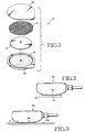
- Figure 1 shows a gel pad assembly 10.
- the gel pad assembly includes a relatively thin (approximately 0.15 cm (0.06 inches)) gel pad 12 which in use is positioned between an ultrasound transducer probe and a selected skin area of a patient.
- gel pad 12 is circular, approximately 6.4 cm (2.5 inches) in diameter, and is made from cellulose or equivalent material, typically impregnated with a mixture of glycerin and water, or other liquid suitable for ultrasound coupling, such as certain oils, including generally water-soluble glycols, such that the opposed surfaces of the pad are pliable, wet and slippery, and will displace any air between the pad and the skin surface and between the pad and the probe surface.
- the term gel pad is used herein as a descriptive, inclusive term to mean a pad having the above described characteristics, displacing air as indicated, even though "gel" per se may not be used in the pad.
- Gel pad 12 is an effective coupling medium between an ultrasound transducer probe and the body of the patient, preventing signal attenuation which would occur in the absence of such a coupling member.
- Gel pad 12 could comprise multiple layers, with the outer layers having the above-described characteristics which displace air from between the pad and the probe and the patient's skin, respectively.
- a given amount of a conventional liquid or semi-liquid ultrasound gel is placed either on the transducer probe, the desired skin area of the patient and/or both.
- the probe is then positioned on the desired skin area, directly on the gel, and the ultrasound procedure is then begun.
- Use of the above-mentioned gel pad assembly 10 replaces the conventional use of the ultrasound gel.
- the ultrasound probe used with the gel pad assembly 10 and discussed herein may have various configurations, but generally refers to the transducer/receiver member which is connected to an ultrasound generating device for transmitting ultrasound signals into a desired area of the body and to receive returning signals therefrom. It should be understood that the ultrasound probe per se is not a part of the gel pad assembly 10.
- Ultrasound is currently used for a wide variety of diagnostic and monitoring purposes, including, for example, monitoring the development of a fetus within the womb and investigating the condition of various areas of the heart and/or the arterial system supplying blood to the heart.
- diagnostic and monitoring purposes including, for example, monitoring the development of a fetus within the womb and investigating the condition of various areas of the heart and/or the arterial system supplying blood to the heart.
- ultrasound There are numerous other applications for ultrasound in the medical field.
- Gel pad assembly 10 further includes a circular section of foam 14.
- the foam section 14 is approximately 6.4 cm (2.5 inches) in diameter (approximately the same diameter as gel pad 12) and 0.34 cm (0.135 inches) thick.
- Upper surface 16 of foam section 14 is either open cell (with a relatively large cell size, typically 0.05 cm (0.020 inches) in diameter) or is convoluted or ribbed. The convolutions may take various configurations; the intent is to create a rather low surface tension between upper surface 16 of foam section 14 and the adjacent surface of gel pad 12.
- Gel pad 12 rests on the upper surface of foam section 14 in the gel pad assembly but is not otherwise secured thereto.
- a thin plastic net section 18 Resting against upper surface 15 of gel pad 12 is a thin plastic net section 18, which has the same diameter and configuration as gel pad 12 and foam section 14, but in the embodiment shown is considerably thinner than foam section 14, approximately 0.08 cm (0.03 inches).
- Net section 18 is typically made of polypropylene or any other thin plastic material with a weave opening size approximately 0.32 cm (0.125 inches) in diameter.
- the purpose of the plastic net section 18 is to prevent gel pad 12 from adhering to a cover 22 of the assembly.
- Net section 18 presents a surface tension to the gel pad that is lower than that presented by the foam section 14, so the gel pad will remain on foam section 14 when cover 22 is removed.
- the net section 18 is adhesively bonded to cover 22.
- Cup portion 20 is shallow, approximately 0.64 cm (0.25 inches) high, and has an internal diameter which is large enough to accommodate gel pad 12, foam section 14 and net section 18.
- Cup portion 20 in the embodiment shown is made of thin plastic, such as polyester.
- Cover portion 22 overlays net section 18, with net section 18 being bonded to the cover portion; cover portion 22 is secured around the periphery thereof to the upper edge of cup portion 20, typically by means of an adhesive.
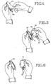
- cover portion 22 is first removed from cup portion 20, simultaneously removing net section 18, as shown in Figure 4.
- the attachment and removal of cover 22 can be accomplished in a number of ways. If an adhesive is used, typically the entire cover will be pulled away by the user. Gel pad 12 is now exposed.
- the ultrasound probe 30 will typically include a curved or partially domed portion 34.
- Domed portion 34 is adapted to be placed on the desired skin area of the patient.
- domed portion 34 is quite smooth so that it has a relatively high surface tension when it contacts the gel pad; in particular, the surface tension is much greater than that of the upper surface of foam section 14.
- Domed portion 34 is pressed against the upper surface of gel pad 12. The physical relationship between domed surface 34 of probe 30, gel pad 12 and foam section 14 at this point is shown most clearly in Figure 2.
- probe 30 is lifted away from the gel pad assembly.
- gel pad 12 remains fixed to domed portion 34 as the probe is moved away.
- gel pad 12 remains positioned firmly on the domed portion of the probe without the operator having to come into contact with the gel pad itself or any of the glycerin thereon.
- the ultrasound probe with the gel pad thereon is positioned on the desired skin area of the patient.
- the gel pad lies against the skin and provides an effective coupling medium between ultrasound probe 30 and the patient's body. Because the gel pad is pliable, slippery and wet, it displaces any air between the pad and the skin of the patient, including any skin irregularities caused by hair, as well as any air between the pad and the surface of the probe.
- the relationship is illustrated in Figure 3, showing probe 30, gel pad 12 which is positioned on the domed portion 34 of the probe, and the skin area 35 of the patient.
- operation of the ultrasound device can begin, with ultrasound signals being generated and transmitted into the body of the patient through the gel pad coupling element; the returning echo signals from the body are also received through the gel pad.
- the ultrasound probe along with the gel pad is ultrasound removed from the patient's body. Because the surface tension between the probe and the gel pad is higher than that between the gel pad and the skin, the gel pad remains.in place on the probe when the probe is removed from the skin. Any residual glycerin/water mixture from the gel pad, which is typically minimal, left on the skin of the patient is either left there to be absorbed into the skin or quickly (and conveniently) wiped clean.
- any residual glycerin/water mixture on the probe dome 34 is also wiped away.
- Foam section 14 which remains in cup portion 20 and cup portion 20 itself may be discarded or may be used to remove the gel pad from the probe. By pressing the probe with the gel pad in place back on the foam section 14 and sliding the probe and the gel pad laterally against the lip of cup portion 20, the gel pad can be removed from the probe without the operator having to come into contact with the gel pad. The used gel pad 12, cup portion 20 and foam section 14 can then all be discarded.
- a gel pad assembly which provides a convenient and effective coupling medium between the ultrasound probe and the skin without the disadvantages of conventional liquid or semi-liquid gel.
Landscapes
- Life Sciences & Earth Sciences (AREA)
- Health & Medical Sciences (AREA)
- Physics & Mathematics (AREA)
- Heart & Thoracic Surgery (AREA)
- Molecular Biology (AREA)
- Nuclear Medicine, Radiotherapy & Molecular Imaging (AREA)
- Pathology (AREA)
- Radiology & Medical Imaging (AREA)
- Engineering & Computer Science (AREA)
- Biomedical Technology (AREA)
- Acoustics & Sound (AREA)
- Medical Informatics (AREA)
- Biophysics (AREA)
- Surgery (AREA)
- Animal Behavior & Ethology (AREA)
- General Health & Medical Sciences (AREA)
- Public Health (AREA)
- Veterinary Medicine (AREA)
- Ultra Sonic Daignosis Equipment (AREA)
- Measurement Of The Respiration, Hearing Ability, Form, And Blood Characteristics Of Living Organisms (AREA)
Claims (12)
- Dispositif à ultrasons comprenant une sonde (30) d'ultrasons et un ensemble de couplage d'ultrasons, l'ensemble de couplage d'ultrasons comprenant :un tampon (12) conçu pour coupler des signaux d'ultrasons entre la sonde (30) d'ultrasons et un corps humain ;un élément (14) formant support sur lequel le tampons (12) peut être mis en position, l'élément (14) formant support étant configuré et disposé de manière à avoir une tension superficielle plus petite entre une surface supérieure de l'élément (14) formant support et le tampon qu'entre la sonde (30) d'ultrasons et le tampon (12), de sorte que lorsque la sonde (30) est appliquée sur le tampon (12) sur l'élément (14) formant support puis en est soulevée, le tampon (12) reste avec la sonde (30) en se séparant de l'élément (14) formant support, de sorte que la sonde peut être mise au voisinage d'une zone (35) souhaitée de la peau du corps, le tampon étant entre la sonde (30) et la zone (35) souhaitée de la peau ; etun réceptacle (20) pour le tampon (12) et l'élément (14) formant support.
- Dispositif à ultrasons suivant la revendication 1, dans lequel le tampon (12) est pliable.
- Dispositif à ultrasons suivant la revendication 1, dans lequel l'élément (14) formant support est de la mousse et sa surface (16) supérieure a une convolution.
- Dispositif à ultrasons suivant la revendication 2, dans lequel le tampon (12) est imprégné d'un liquide conducteur des ultrasons, le liquide étant apte à déplacer de l'air entre le tampon (12) et la sonde (30), ainsi qu'entre le tampon et la zone souhaitée de la peau lorsque la sonde et le tampon imprégné sont mis en position de fonctionnement sur la zone souhaitée de la peau.
- Dispositif à ultrasons suivant la revendication 1, dans lequel l'élément (14) formant support est une matière de mousse à cellule ouverte.
- Dispositif à ultrasons suivant la revendication 1, comprenant une partie (22) amovible formant couvercle qui s'étend sur le tampon (12) et l'élément (14) formant support et les recouvre et est fixée à un bord supérieur du réceptacle (20).
- Dispositif à ultrasons suivant la revendication 6, comprenant un élément (18) en forme de filet disposé entre le tampon (12) et la partie (22) formant couvercle, l'élément (18) en forme de filet étant fixé à la partie (22) formant couvercle et la tension superficielle entre l'élément (18) formant filet et le tampon (12) est inférieure à celle entre le tampon (12) et l'élément (20) formant support, de sorte que lorsque la partie (22) formant couvercle est enlevée, le tampon (12) reste sur l'élément (14) formant support.
- Dispositif à ultrasons suivant la revendication 7, dans lequel le tampon (12), l'élément (14) formant support et l'élément (18) formant filet ont approximativement la même configuration et le même contour.
- Tampon (12) à utiliser avec une sonde (30) à ultrasons pour coupler des signaux d'ultrasons à un corps humain, comprenant :un élément (12) formant tampon en un matériau imprégné d'un liquide conducteur des ultrasons, de façon à ce que le tampon soit apte à conduire des signaux d'ultrasons d'une source (30) formant sonde à une zone (35) de la peau du corps humain, le tampon imprégné étant pliable et mouillé sur des surfaces opposées respectives, de sorte que de l'air compris entre le tampon (12) et, respectivement, la sonde (30) et la surface (35) de la peau est refoulé lorsque le tampon est mis en position de fonctionnement en contact avec la sonde (30) et avec la surface (35) de la peau.
- Tampon suivant la revendication 9, dans lequel le matériau du tampon est du matériau cellulosique.
- Tampon suivant la revendication 9, dans lequel le liquide est une combinaison d'eau et de glycérine.
- Procédé de préparation d'une sonde (30) d'ultrasons en utilisant un ensemble de couplage à ultrasons comprenant :un tampon (12) destiné à coupler des signaux d'ultrasons entre la sonde (30) d'ultrasons et un corps humain, un élément (14) formant support sur lequel est mis le tampon et un réceptacle (20) pour le tampon et l'élément formant support, le procédé comprenant les stades dans lesquels :on amène la sonde (30) d'ultrasons en contact avec une surface supérieure du tampon (12) et on soulève la sonde (30) d'ultrasons en l'éloignant de l'élément (14) formant support ;la tension superficielle entre le tampon (12) et la sonde (30) d'ultrasons étant plus grande que la tension superficielle entre le tampon (12) et l'élément (14) formant support, de façon à ce que le tampon (12) reste avec la sonde (30) alors que l'on éloigne la sonde (30) de l'élément (14) formant support.
Applications Claiming Priority (3)
| Application Number | Priority Date | Filing Date | Title |
|---|---|---|---|
| US777581 | 1996-12-31 | ||
| US08/777,581 US5782767A (en) | 1996-12-31 | 1996-12-31 | Coupling pad for use with medical ultrasound devices |
| PCT/US1997/024262 WO1998029036A1 (fr) | 1996-12-31 | 1997-12-24 | Boitier de couplage destine a des dispositifs medicaux a ultrasons |
Publications (3)
| Publication Number | Publication Date |
|---|---|
| EP0973448A1 EP0973448A1 (fr) | 2000-01-26 |
| EP0973448A4 EP0973448A4 (fr) | 2000-04-19 |
| EP0973448B1 true EP0973448B1 (fr) | 2005-08-10 |
Family
ID=25110643
Family Applications (1)
| Application Number | Title | Priority Date | Filing Date |
|---|---|---|---|
| EP97954661A Expired - Lifetime EP0973448B1 (fr) | 1996-12-31 | 1997-12-24 | Boitier de couplage destine a des dispositifs medicaux a ultrasons |
Country Status (6)
| Country | Link |
|---|---|
| US (1) | US5782767A (fr) |
| EP (1) | EP0973448B1 (fr) |
| JP (1) | JP2001507603A (fr) |
| AT (1) | ATE301422T1 (fr) |
| DE (1) | DE69733971D1 (fr) |
| WO (1) | WO1998029036A1 (fr) |
Families Citing this family (87)
| Publication number | Priority date | Publication date | Assignee | Title |
|---|---|---|---|---|
| US5904659A (en) | 1997-02-14 | 1999-05-18 | Exogen, Inc. | Ultrasonic treatment for wounds |
| EP1014858A4 (fr) * | 1997-08-19 | 2005-07-13 | John D Mendlein | Films et dispositifs de transmission d'ultrasons notamment pour surfaces de transducteurs hygieniques |
| EP1156891B1 (fr) * | 1999-03-01 | 2005-11-30 | MedAcoustics, Inc. | Reseau de detecteurs acoustiques en boitier extra-plat et detecteurs dotes de lignes de transmission plissees et procedes correspondants |
| WO2000076406A1 (fr) | 1999-06-14 | 2000-12-21 | Exogen, Inc. | Procede et kit de reparation tissulaire induite par cavitation avec des ultrasons de faible intensite |
| US6524246B1 (en) * | 2000-10-13 | 2003-02-25 | Sonocine, Inc. | Ultrasonic cellular tissue screening tool |
| US7429248B1 (en) | 2001-08-09 | 2008-09-30 | Exogen, Inc. | Method and apparatus for controlling acoustic modes in tissue healing applications |
| US6719699B2 (en) | 2002-02-07 | 2004-04-13 | Sonotech, Inc. | Adhesive hydrophilic membranes as couplants in ultrasound imaging applications |
| GB2391625A (en) | 2002-08-09 | 2004-02-11 | Diagnostic Ultrasound Europ B | Instantaneous ultrasonic echo measurement of bladder urine volume with a limited number of ultrasound beams |
| US7819806B2 (en) | 2002-06-07 | 2010-10-26 | Verathon Inc. | System and method to identify and measure organ wall boundaries |
| US7520857B2 (en) * | 2002-06-07 | 2009-04-21 | Verathon Inc. | 3D ultrasound-based instrument for non-invasive measurement of amniotic fluid volume |
| US8221321B2 (en) | 2002-06-07 | 2012-07-17 | Verathon Inc. | Systems and methods for quantification and classification of fluids in human cavities in ultrasound images |
| US8221322B2 (en) | 2002-06-07 | 2012-07-17 | Verathon Inc. | Systems and methods to improve clarity in ultrasound images |
| EP1415596A1 (fr) * | 2002-10-28 | 2004-05-06 | Ulrich André Baumann | Dispositif de mesure de pression pour un dispositif de mesures ultrasonores |
| GB0300742D0 (en) * | 2003-01-14 | 2003-02-12 | Moores Heather E | Ultrasound coupling pad |
| US6843771B2 (en) * | 2003-01-15 | 2005-01-18 | Salutron, Inc. | Ultrasonic monitor for measuring heart rate and blood flow rate |
| US7399278B1 (en) | 2003-05-05 | 2008-07-15 | Los Angeles Biomedical Research Institute At Harbor-Ucla Medical Center | Method and system for measuring amniotic fluid volume and/or assessing fetal weight |
| US7029446B2 (en) * | 2003-10-30 | 2006-04-18 | Martin Edmund Wendelken | Standoff holder and standoff pad for ultrasound probe |
| EP1711228A2 (fr) * | 2003-12-11 | 2006-10-18 | Hans-Werner Bender | Dispositif constitue d'un applicateur de son et d'un element de support |
| US7815575B2 (en) * | 2005-05-09 | 2010-10-19 | Salutron, Inc. | Ultrasonic monitor with a biocompatible oil based transmission medium |
| WO2007014292A2 (fr) * | 2005-07-25 | 2007-02-01 | U-Systems, Inc. | Surface de compression pour balayage de tissu par ultrasons |
| US8784336B2 (en) | 2005-08-24 | 2014-07-22 | C. R. Bard, Inc. | Stylet apparatuses and methods of manufacture |
| US8764664B2 (en) * | 2005-11-28 | 2014-07-01 | Vizyontech Imaging, Inc. | Methods and apparatus for conformable medical data acquisition pad and configurable imaging system |
| EP1968704A2 (fr) * | 2006-01-06 | 2008-09-17 | Smith and Nephew, Inc. | Applicateur de traitement sans attache |
| JP2007200507A (ja) * | 2006-01-30 | 2007-08-09 | Orion Denki Kk | トレイを備えたディスク装置 |
| US8388546B2 (en) | 2006-10-23 | 2013-03-05 | Bard Access Systems, Inc. | Method of locating the tip of a central venous catheter |
| US7794407B2 (en) | 2006-10-23 | 2010-09-14 | Bard Access Systems, Inc. | Method of locating the tip of a central venous catheter |
| US20080139944A1 (en) * | 2006-12-08 | 2008-06-12 | Weymer Raymond F | Devices for covering ultrasound probes of ultrasound machines |
| DE102006059413A1 (de) * | 2006-12-15 | 2008-06-26 | Fraunhofer-Gesellschaft zur Förderung der angewandten Forschung e.V. | Verfahren und Vorrichtung zur zerstörungsfreien Prüfkörperuntersuchung mittels Ultraschall längs einer nicht ebenen Prüfkörperoberfläche |
| US8231533B2 (en) * | 2007-02-16 | 2012-07-31 | Buchalter Neal | Ultrasound coupling device |
| US8167803B2 (en) | 2007-05-16 | 2012-05-01 | Verathon Inc. | System and method for bladder detection using harmonic imaging |
| US8226562B2 (en) * | 2007-08-10 | 2012-07-24 | Ultrasonix Medical Corporation | Hand-held ultrasound system having sterile enclosure |
| US10449330B2 (en) | 2007-11-26 | 2019-10-22 | C. R. Bard, Inc. | Magnetic element-equipped needle assemblies |
| US9649048B2 (en) | 2007-11-26 | 2017-05-16 | C. R. Bard, Inc. | Systems and methods for breaching a sterile field for intravascular placement of a catheter |
| US8849382B2 (en) | 2007-11-26 | 2014-09-30 | C. R. Bard, Inc. | Apparatus and display methods relating to intravascular placement of a catheter |
| US9521961B2 (en) | 2007-11-26 | 2016-12-20 | C. R. Bard, Inc. | Systems and methods for guiding a medical instrument |
| CN101925333B (zh) | 2007-11-26 | 2014-02-12 | C·R·巴德股份有限公司 | 用于脉管系统内的导管放置的集成系统 |
| US10751509B2 (en) | 2007-11-26 | 2020-08-25 | C. R. Bard, Inc. | Iconic representations for guidance of an indwelling medical device |
| US10524691B2 (en) | 2007-11-26 | 2020-01-07 | C. R. Bard, Inc. | Needle assembly including an aligned magnetic element |
| US8781555B2 (en) | 2007-11-26 | 2014-07-15 | C. R. Bard, Inc. | System for placement of a catheter including a signal-generating stylet |
| US8478382B2 (en) | 2008-02-11 | 2013-07-02 | C. R. Bard, Inc. | Systems and methods for positioning a catheter |
| CN105126262B (zh) | 2008-07-14 | 2019-03-22 | 代理并代表亚利桑那州立大学的亚利桑那董事会 | 使用超声用于调节细胞活性的方法和装置 |
| JP5658151B2 (ja) | 2008-08-07 | 2015-01-21 | ベラソン インコーポレイテッドVerathon Inc. | 腹部大動脈瘤の直径を測定するための装置、システム、方法 |
| US9901714B2 (en) | 2008-08-22 | 2018-02-27 | C. R. Bard, Inc. | Catheter assembly including ECG sensor and magnetic assemblies |
| US8437833B2 (en) | 2008-10-07 | 2013-05-07 | Bard Access Systems, Inc. | Percutaneous magnetic gastrostomy |
| US9532724B2 (en) | 2009-06-12 | 2017-01-03 | Bard Access Systems, Inc. | Apparatus and method for catheter navigation using endovascular energy mapping |
| RU2549998C2 (ru) | 2009-06-12 | 2015-05-10 | Бард Аксесс Системс, Инк. | Способ позиционирования конца катетера |
| WO2011019760A2 (fr) | 2009-08-10 | 2011-02-17 | Romedex International Srl | Dispositifs et procédés pour électrographie endovasculaire |
| US8475377B2 (en) * | 2009-09-28 | 2013-07-02 | First Sense Medical, Llc | Multi-modality breast cancer test system |
| CN102665541B (zh) | 2009-09-29 | 2016-01-13 | C·R·巴德股份有限公司 | 与用于导管的血管内放置的设备一起使用的探针 |
| WO2011044421A1 (fr) | 2009-10-08 | 2011-04-14 | C. R. Bard, Inc. | Entretoises utilisées avec une sonde ultrasonore |
| CA2779842C (fr) | 2009-11-04 | 2021-06-22 | Arizona Board Of Regents For And On Behalf Of Arizona State University | Dispositifs et methodes de modulation de l'activite cerebrale |
| WO2011097312A1 (fr) | 2010-02-02 | 2011-08-11 | C.R. Bard, Inc. | Appareil et procédé destinés à la navigation d'un cathéter et à la localisation d'une pointe |
| US20110196238A1 (en) * | 2010-02-05 | 2011-08-11 | Jacobson Nathan A | System and Method for Fetal Heart Monitoring Using Ultrasound |
| CA3054544C (fr) | 2010-05-28 | 2022-01-04 | C.R. Bard, Inc. | Appareil convenant a une utilisation avec un systeme de guidage d'insertion d'aiguille |
| EP2912999B1 (fr) | 2010-05-28 | 2022-06-29 | C. R. Bard, Inc. | Appareil destiné à être utilisé avec un système de guidage d'insertion d'aiguille |
| JP2013535301A (ja) | 2010-08-09 | 2013-09-12 | シー・アール・バード・インコーポレーテッド | 超音波プローブヘッド用支持・カバー構造 |
| BR112013002431B1 (pt) | 2010-08-20 | 2021-06-29 | C.R. Bard, Inc | Sistema para a reconfirmação da posição de um cateter no interior de um paciente |
| CN103189009B (zh) | 2010-10-29 | 2016-09-07 | C·R·巴德股份有限公司 | 医疗设备的生物阻抗辅助放置 |
| AU2012278809B2 (en) | 2011-07-06 | 2016-09-29 | C.R. Bard, Inc. | Needle length determination and calibration for insertion guidance system |
| USD699359S1 (en) | 2011-08-09 | 2014-02-11 | C. R. Bard, Inc. | Ultrasound probe head |
| USD724745S1 (en) | 2011-08-09 | 2015-03-17 | C. R. Bard, Inc. | Cap for an ultrasound probe |
| WO2013059833A1 (fr) | 2011-10-21 | 2013-04-25 | Neurotrek, Inc. | Procédé et système de communication directe |
| WO2013070775A1 (fr) | 2011-11-07 | 2013-05-16 | C.R. Bard, Inc | Insert à base d'hydrogel renforcé pour ultrasons |
| EP2861153A4 (fr) | 2012-06-15 | 2016-10-19 | Bard Inc C R | Appareil et procédés permettant la détection d'un capuchon amovible sur une sonde à ultrasons |
| WO2014024286A1 (fr) * | 2012-08-09 | 2014-02-13 | タキロン株式会社 | Écarteur pour montage d'une sonde de diagnostic à ultrasons |
| WO2014036170A1 (fr) | 2012-08-29 | 2014-03-06 | Thync, Inc. | Systèmes et dispositifs pour coupler une énergie ultrasonore au corps |
| CN105979868B (zh) | 2014-02-06 | 2020-03-10 | C·R·巴德股份有限公司 | 用于血管内装置的导向和放置的系统和方法 |
| KR101563500B1 (ko) * | 2014-02-28 | 2015-10-27 | 삼성메디슨 주식회사 | 프로브용 겔 패치 및 이를 포함한 초음파 진단 장치 |
| US10980510B2 (en) | 2015-01-08 | 2021-04-20 | Casey K. Scully | Ultrasound probe couplers and related methods |
| US10507008B2 (en) | 2015-01-08 | 2019-12-17 | Casey K. Scully | Ultrasound probe couplers and related methods |
| US10973584B2 (en) | 2015-01-19 | 2021-04-13 | Bard Access Systems, Inc. | Device and method for vascular access |
| JP6421277B2 (ja) * | 2015-05-15 | 2018-11-07 | ハジッチ、アドミル | 超音波プローブカバー及び使用方法 |
| WO2016210325A1 (fr) | 2015-06-26 | 2016-12-29 | C.R. Bard, Inc. | Interface de raccord pour système de positionnement de cathéter basé sur ecg |
| WO2017083088A1 (fr) | 2015-11-09 | 2017-05-18 | Healthcare Evolution, Llc | Dispositifs d'élément de protection et procédés pour une utilisation dans des procédures ultrasonores |
| GB201519985D0 (en) * | 2015-11-12 | 2015-12-30 | Respinor As | Ultrasonic method and apparatus for respiration monitoring |
| US11000207B2 (en) | 2016-01-29 | 2021-05-11 | C. R. Bard, Inc. | Multiple coil system for tracking a medical device |
| US11006925B2 (en) * | 2016-05-30 | 2021-05-18 | Canon Medical Systems Corporation | Probe adapter, ultrasonic probe, and ultrasonic diagnostic apparatus |
| JP6119013B1 (ja) * | 2016-09-26 | 2017-04-26 | 本多電子株式会社 | 歯科用超音波診断装置及び歯科用超音波プローブ |
| US20200061393A1 (en) * | 2016-12-03 | 2020-02-27 | Zetroz Systems Llc | Ultrasound coupling patch with gel capture feature |
| WO2019191278A1 (fr) | 2018-03-27 | 2019-10-03 | Civco Medical Instruments Co., Inc. | Couvercles pour sonde ultrasonore |
| CN112867443B (zh) | 2018-10-16 | 2024-04-26 | 巴德阿克塞斯系统股份有限公司 | 用于建立电连接的安全装备连接系统及其方法 |
| US11541594B2 (en) * | 2018-11-06 | 2023-01-03 | Ricoh Company, Ltd. | Ultrasonic propagation member and method for producing same |
| KR102146953B1 (ko) * | 2019-01-04 | 2020-08-21 | 주식회사 엠트리케어 | 혈류 및 혈관상태 측정장치 |
| US12544101B2 (en) | 2019-01-30 | 2026-02-10 | Bard Access Systems, Inc. | Systems and methods for tracking medical devices |
| US11497467B2 (en) | 2019-08-30 | 2022-11-15 | Bard Access Systems, Inc. | Probe head-cover applicator and method thereof |
| US11723687B2 (en) | 2019-12-11 | 2023-08-15 | Medline Industries, Lp | Window dressing for use with ultrasonic aid in venipuncture |
| US12514455B2 (en) | 2021-12-06 | 2026-01-06 | AngioLytics LLC | Infrared signal capture and analysis |
Family Cites Families (8)
| Publication number | Priority date | Publication date | Assignee | Title |
|---|---|---|---|---|
| US4556066A (en) * | 1983-11-04 | 1985-12-03 | The Kendall Company | Ultrasound acoustical coupling pad |
| JPS63220847A (ja) * | 1987-03-10 | 1988-09-14 | 松下電器産業株式会社 | 超音波探触子 |
| EP0413028B1 (fr) * | 1988-08-30 | 1995-07-12 | Fujitsu Limited | Coupleur acoustique |
| EP0420758B1 (fr) * | 1989-09-29 | 1995-07-26 | Terumo Kabushiki Kaisha | Elément de couplage ultrasonore et méthode de fabrication |
| US5076149A (en) * | 1990-12-07 | 1991-12-31 | Inertia Dynamics Corporation | Wrist pin, piston assembly and method for making same |
| EP0527651A1 (fr) * | 1991-08-14 | 1993-02-17 | Advanced Technology Laboratories, Inc. | Espanceur acoustique pour tête de transducteur ultra-sonore |
| US5394877A (en) * | 1993-04-01 | 1995-03-07 | Axon Medical, Inc. | Ultrasound medical diagnostic device having a coupling medium providing self-adherence to a patient |
| JPH07136162A (ja) * | 1993-11-17 | 1995-05-30 | Fujitsu Ltd | 超音波カプラ |
-
1996
- 1996-12-31 US US08/777,581 patent/US5782767A/en not_active Expired - Fee Related
-
1997
- 1997-12-24 EP EP97954661A patent/EP0973448B1/fr not_active Expired - Lifetime
- 1997-12-24 JP JP53034898A patent/JP2001507603A/ja active Pending
- 1997-12-24 WO PCT/US1997/024262 patent/WO1998029036A1/fr not_active Ceased
- 1997-12-24 DE DE69733971T patent/DE69733971D1/de not_active Expired - Lifetime
- 1997-12-24 AT AT97954661T patent/ATE301422T1/de not_active IP Right Cessation
Also Published As
| Publication number | Publication date |
|---|---|
| WO1998029036A1 (fr) | 1998-07-09 |
| US5782767A (en) | 1998-07-21 |
| JP2001507603A (ja) | 2001-06-12 |
| EP0973448A4 (fr) | 2000-04-19 |
| ATE301422T1 (de) | 2005-08-15 |
| DE69733971D1 (de) | 2005-09-15 |
| EP0973448A1 (fr) | 2000-01-26 |
Similar Documents
| Publication | Publication Date | Title |
|---|---|---|
| EP0973448B1 (fr) | Boitier de couplage destine a des dispositifs medicaux a ultrasons | |
| US6132378A (en) | Cover for ultrasound probe | |
| US4545385A (en) | Ultrasound examination device for scanning body parts | |
| US8231533B2 (en) | Ultrasound coupling device | |
| US7393326B2 (en) | Apparatus for screening and diagnosing by dual stethoscopic and Doppler detection | |
| US20080139944A1 (en) | Devices for covering ultrasound probes of ultrasound machines | |
| JP2776541B2 (ja) | 超音波探触子用接触端子 | |
| CN108324322B (zh) | 一种超声探头隔离护套的安装方法 | |
| ATE408374T1 (de) | Photoakustische mamma-abtastvorrichtung | |
| US20110264012A1 (en) | Compliant couplant with liquid reservoir for transducer | |
| EP0988011A1 (fr) | Ensemble d'ecouteurs pour dispositif de depistage de la surdite | |
| JPH05506590A (ja) | 吸引カップを備えた組織を傷つけない医学上の探針 | |
| JP2002513661A (ja) | 超音波包帯 | |
| JP2007518427A (ja) | 生理学的作用の発生を検出を容易にするためのバイオフィルターパッド、及びその方法、並びに胎児活性度看視装置 | |
| US5913309A (en) | Disposable element for use with a hearing screener | |
| EP0527651A1 (fr) | Espanceur acoustique pour tête de transducteur ultra-sonore | |
| JP2002336256A (ja) | 乳房用超音波計測装置 | |
| JPH10234734A (ja) | 超音波プローブ | |
| US5113848A (en) | Apparatus for shock wave therapy | |
| EP0439514A1 (fr) | Plaque support de capteur amelioree a anneau detachable | |
| CN209863876U (zh) | 一种超声探头隔离护套 | |
| CN219250221U (zh) | 一种专用于隆突状皮肤病变及乳头区超声检查的辅助垫 | |
| CN223873957U (zh) | 一种多频超声探头 | |
| JPS60249943A (ja) | 医用超音波診断装置用水槽 | |
| JPS6274811U (fr) |
Legal Events
| Date | Code | Title | Description |
|---|---|---|---|
| PUAI | Public reference made under article 153(3) epc to a published international application that has entered the european phase |
Free format text: ORIGINAL CODE: 0009012 |
|
| 17P | Request for examination filed |
Effective date: 19990714 |
|
| AK | Designated contracting states |
Kind code of ref document: A1 Designated state(s): AT BE CH DE DK ES FI FR GB GR IE IT LI LU MC NL PT SE |
|
| A4 | Supplementary search report drawn up and despatched |
Effective date: 20000302 |
|
| AK | Designated contracting states |
Kind code of ref document: A4 Designated state(s): AT BE CH DE DK ES FI FR GB GR IE IT LI LU MC NL PT SE |
|
| 17Q | First examination report despatched |
Effective date: 20030915 |
|
| GRAP | Despatch of communication of intention to grant a patent |
Free format text: ORIGINAL CODE: EPIDOSNIGR1 |
|
| GRAS | Grant fee paid |
Free format text: ORIGINAL CODE: EPIDOSNIGR3 |
|
| GRAA | (expected) grant |
Free format text: ORIGINAL CODE: 0009210 |
|
| AK | Designated contracting states |
Kind code of ref document: B1 Designated state(s): AT BE CH DE DK ES FI FR GB GR IE IT LI LU MC NL PT SE |
|
| PG25 | Lapsed in a contracting state [announced via postgrant information from national office to epo] |
Ref country code: LI Free format text: LAPSE BECAUSE OF FAILURE TO SUBMIT A TRANSLATION OF THE DESCRIPTION OR TO PAY THE FEE WITHIN THE PRESCRIBED TIME-LIMIT Effective date: 20050810 Ref country code: IT Free format text: LAPSE BECAUSE OF FAILURE TO SUBMIT A TRANSLATION OF THE DESCRIPTION OR TO PAY THE FEE WITHIN THE PRESCRIBED TIME-LIMIT;WARNING: LAPSES OF ITALIAN PATENTS WITH EFFECTIVE DATE BEFORE 2007 MAY HAVE OCCURRED AT ANY TIME BEFORE 2007. THE CORRECT EFFECTIVE DATE MAY BE DIFFERENT FROM THE ONE RECORDED. Effective date: 20050810 Ref country code: FI Free format text: LAPSE BECAUSE OF FAILURE TO SUBMIT A TRANSLATION OF THE DESCRIPTION OR TO PAY THE FEE WITHIN THE PRESCRIBED TIME-LIMIT Effective date: 20050810 Ref country code: CH Free format text: LAPSE BECAUSE OF FAILURE TO SUBMIT A TRANSLATION OF THE DESCRIPTION OR TO PAY THE FEE WITHIN THE PRESCRIBED TIME-LIMIT Effective date: 20050810 Ref country code: BE Free format text: LAPSE BECAUSE OF FAILURE TO SUBMIT A TRANSLATION OF THE DESCRIPTION OR TO PAY THE FEE WITHIN THE PRESCRIBED TIME-LIMIT Effective date: 20050810 Ref country code: AT Free format text: LAPSE BECAUSE OF FAILURE TO SUBMIT A TRANSLATION OF THE DESCRIPTION OR TO PAY THE FEE WITHIN THE PRESCRIBED TIME-LIMIT Effective date: 20050810 |
|
| REG | Reference to a national code |
Ref country code: GB Ref legal event code: FG4D |
|
| REG | Reference to a national code |
Ref country code: CH Ref legal event code: EP |
|
| REG | Reference to a national code |
Ref country code: IE Ref legal event code: FG4D |
|
| REF | Corresponds to: |
Ref document number: 69733971 Country of ref document: DE Date of ref document: 20050915 Kind code of ref document: P |
|
| PG25 | Lapsed in a contracting state [announced via postgrant information from national office to epo] |
Ref country code: SE Free format text: LAPSE BECAUSE OF FAILURE TO SUBMIT A TRANSLATION OF THE DESCRIPTION OR TO PAY THE FEE WITHIN THE PRESCRIBED TIME-LIMIT Effective date: 20051110 Ref country code: GR Free format text: LAPSE BECAUSE OF FAILURE TO SUBMIT A TRANSLATION OF THE DESCRIPTION OR TO PAY THE FEE WITHIN THE PRESCRIBED TIME-LIMIT Effective date: 20051110 Ref country code: DK Free format text: LAPSE BECAUSE OF FAILURE TO SUBMIT A TRANSLATION OF THE DESCRIPTION OR TO PAY THE FEE WITHIN THE PRESCRIBED TIME-LIMIT Effective date: 20051110 |
|
| PG25 | Lapsed in a contracting state [announced via postgrant information from national office to epo] |
Ref country code: DE Free format text: LAPSE BECAUSE OF FAILURE TO SUBMIT A TRANSLATION OF THE DESCRIPTION OR TO PAY THE FEE WITHIN THE PRESCRIBED TIME-LIMIT Effective date: 20051111 |
|
| PG25 | Lapsed in a contracting state [announced via postgrant information from national office to epo] |
Ref country code: ES Free format text: LAPSE BECAUSE OF FAILURE TO SUBMIT A TRANSLATION OF THE DESCRIPTION OR TO PAY THE FEE WITHIN THE PRESCRIBED TIME-LIMIT Effective date: 20051121 |
|
| PG25 | Lapsed in a contracting state [announced via postgrant information from national office to epo] |
Ref country code: IE Free format text: LAPSE BECAUSE OF NON-PAYMENT OF DUE FEES Effective date: 20051229 |
|
| PG25 | Lapsed in a contracting state [announced via postgrant information from national office to epo] |
Ref country code: MC Free format text: LAPSE BECAUSE OF NON-PAYMENT OF DUE FEES Effective date: 20051231 Ref country code: LU Free format text: LAPSE BECAUSE OF NON-PAYMENT OF DUE FEES Effective date: 20051231 |
|
| PG25 | Lapsed in a contracting state [announced via postgrant information from national office to epo] |
Ref country code: PT Free format text: LAPSE BECAUSE OF FAILURE TO SUBMIT A TRANSLATION OF THE DESCRIPTION OR TO PAY THE FEE WITHIN THE PRESCRIBED TIME-LIMIT Effective date: 20060110 |
|
| REG | Reference to a national code |
Ref country code: CH Ref legal event code: PL |
|
| ET | Fr: translation filed | ||
| PLBE | No opposition filed within time limit |
Free format text: ORIGINAL CODE: 0009261 |
|
| STAA | Information on the status of an ep patent application or granted ep patent |
Free format text: STATUS: NO OPPOSITION FILED WITHIN TIME LIMIT |
|
| 26N | No opposition filed |
Effective date: 20060511 |
|
| REG | Reference to a national code |
Ref country code: IE Ref legal event code: MM4A |
|
| PGFP | Annual fee paid to national office [announced via postgrant information from national office to epo] |
Ref country code: GB Payment date: 20061222 Year of fee payment: 10 |
|
| PGFP | Annual fee paid to national office [announced via postgrant information from national office to epo] |
Ref country code: NL Payment date: 20061229 Year of fee payment: 10 |
|
| PGFP | Annual fee paid to national office [announced via postgrant information from national office to epo] |
Ref country code: FR Payment date: 20061229 Year of fee payment: 10 |
|
| GBPC | Gb: european patent ceased through non-payment of renewal fee |
Effective date: 20071224 |
|
| NLV4 | Nl: lapsed or anulled due to non-payment of the annual fee |
Effective date: 20080701 |
|
| REG | Reference to a national code |
Ref country code: FR Ref legal event code: ST Effective date: 20081020 |
|
| PG25 | Lapsed in a contracting state [announced via postgrant information from national office to epo] |
Ref country code: NL Free format text: LAPSE BECAUSE OF NON-PAYMENT OF DUE FEES Effective date: 20080701 |
|
| PG25 | Lapsed in a contracting state [announced via postgrant information from national office to epo] |
Ref country code: GB Free format text: LAPSE BECAUSE OF NON-PAYMENT OF DUE FEES Effective date: 20071224 |
|
| PG25 | Lapsed in a contracting state [announced via postgrant information from national office to epo] |
Ref country code: FR Free format text: LAPSE BECAUSE OF NON-PAYMENT OF DUE FEES Effective date: 20071231 |