EP0974395B1 - Système de réacteur - Google Patents
Système de réacteur Download PDFInfo
- Publication number
- EP0974395B1 EP0974395B1 EP99114419A EP99114419A EP0974395B1 EP 0974395 B1 EP0974395 B1 EP 0974395B1 EP 99114419 A EP99114419 A EP 99114419A EP 99114419 A EP99114419 A EP 99114419A EP 0974395 B1 EP0974395 B1 EP 0974395B1
- Authority
- EP
- European Patent Office
- Prior art keywords
- reactor
- gas
- liquid
- oxygen
- reaction
- Prior art date
- Legal status (The legal status is an assumption and is not a legal conclusion. Google has not performed a legal analysis and makes no representation as to the accuracy of the status listed.)
- Expired - Lifetime
Links
- 239000007788 liquid Substances 0.000 claims abstract description 126
- 238000006243 chemical reaction Methods 0.000 claims abstract description 78
- 239000000376 reactant Substances 0.000 claims description 32
- 239000002253 acid Substances 0.000 claims description 15
- 239000000047 product Substances 0.000 claims description 15
- 238000000034 method Methods 0.000 claims description 8
- 125000001931 aliphatic group Chemical group 0.000 claims description 7
- 239000007795 chemical reaction product Substances 0.000 claims description 7
- 230000008569 process Effects 0.000 claims description 7
- 230000003134 recirculating effect Effects 0.000 claims description 6
- 230000001590 oxidative effect Effects 0.000 claims description 3
- 125000002485 formyl group Chemical class [H]C(*)=O 0.000 claims 2
- 238000012546 transfer Methods 0.000 abstract description 76
- 239000007787 solid Substances 0.000 abstract description 3
- 239000007789 gas Substances 0.000 description 138
- QVGXLLKOCUKJST-UHFFFAOYSA-N atomic oxygen Chemical compound [O] QVGXLLKOCUKJST-UHFFFAOYSA-N 0.000 description 79
- 239000001301 oxygen Substances 0.000 description 79
- 229910052760 oxygen Inorganic materials 0.000 description 79
- 238000007254 oxidation reaction Methods 0.000 description 25
- 239000006227 byproduct Substances 0.000 description 23
- 230000003647 oxidation Effects 0.000 description 22
- 238000005755 formation reaction Methods 0.000 description 21
- 239000007791 liquid phase Substances 0.000 description 17
- 230000015572 biosynthetic process Effects 0.000 description 16
- IJGRMHOSHXDMSA-UHFFFAOYSA-N Atomic nitrogen Chemical compound N#N IJGRMHOSHXDMSA-UHFFFAOYSA-N 0.000 description 14
- 238000001816 cooling Methods 0.000 description 14
- 230000001965 increasing effect Effects 0.000 description 14
- 150000001299 aldehydes Chemical class 0.000 description 13
- 238000013461 design Methods 0.000 description 11
- 239000012530 fluid Substances 0.000 description 10
- 239000012071 phase Substances 0.000 description 10
- 239000002912 waste gas Substances 0.000 description 10
- 238000010926 purge Methods 0.000 description 9
- 239000000498 cooling water Substances 0.000 description 8
- 238000005984 hydrogenation reaction Methods 0.000 description 8
- 238000004519 manufacturing process Methods 0.000 description 8
- 239000000203 mixture Substances 0.000 description 7
- 229910052757 nitrogen Inorganic materials 0.000 description 7
- 239000012295 chemical reaction liquid Substances 0.000 description 6
- 230000009286 beneficial effect Effects 0.000 description 5
- 230000008901 benefit Effects 0.000 description 5
- 238000004891 communication Methods 0.000 description 5
- 239000012809 cooling fluid Substances 0.000 description 5
- 230000007423 decrease Effects 0.000 description 5
- 238000009826 distribution Methods 0.000 description 5
- 150000004715 keto acids Chemical class 0.000 description 5
- 238000005086 pumping Methods 0.000 description 5
- 150000007513 acids Chemical class 0.000 description 4
- 230000009471 action Effects 0.000 description 4
- 239000002826 coolant Substances 0.000 description 4
- 235000003642 hunger Nutrition 0.000 description 4
- 230000006872 improvement Effects 0.000 description 4
- 239000000314 lubricant Substances 0.000 description 4
- 230000037351 starvation Effects 0.000 description 4
- 239000000126 substance Substances 0.000 description 4
- NQPDZGIKBAWPEJ-UHFFFAOYSA-N valeric acid Chemical compound CCCCC(O)=O NQPDZGIKBAWPEJ-UHFFFAOYSA-N 0.000 description 4
- MYMOFIZGZYHOMD-UHFFFAOYSA-N Dioxygen Chemical compound O=O MYMOFIZGZYHOMD-UHFFFAOYSA-N 0.000 description 3
- 125000004432 carbon atom Chemical group C* 0.000 description 3
- 230000003247 decreasing effect Effects 0.000 description 3
- 239000011261 inert gas Substances 0.000 description 3
- BYGQBDHUGHBGMD-UHFFFAOYSA-N 2-methylbutanal Chemical compound CCC(C)C=O BYGQBDHUGHBGMD-UHFFFAOYSA-N 0.000 description 2
- URLKBWYHVLBVBO-UHFFFAOYSA-N Para-Xylene Chemical group CC1=CC=C(C)C=C1 URLKBWYHVLBVBO-UHFFFAOYSA-N 0.000 description 2
- NBBJYMSMWIIQGU-UHFFFAOYSA-N Propionic aldehyde Chemical compound CCC=O NBBJYMSMWIIQGU-UHFFFAOYSA-N 0.000 description 2
- 238000013459 approach Methods 0.000 description 2
- 238000012864 cross contamination Methods 0.000 description 2
- RWGFKTVRMDUZSP-UHFFFAOYSA-N cumene Chemical compound CC(C)C1=CC=CC=C1 RWGFKTVRMDUZSP-UHFFFAOYSA-N 0.000 description 2
- 239000003085 diluting agent Substances 0.000 description 2
- WOZVHXUHUFLZGK-UHFFFAOYSA-N dimethyl terephthalate Chemical compound COC(=O)C1=CC=C(C(=O)OC)C=C1 WOZVHXUHUFLZGK-UHFFFAOYSA-N 0.000 description 2
- XBDQKXXYIPTUBI-UHFFFAOYSA-N dimethylselenoniopropionate Natural products CCC(O)=O XBDQKXXYIPTUBI-UHFFFAOYSA-N 0.000 description 2
- 239000006185 dispersion Substances 0.000 description 2
- 230000000694 effects Effects 0.000 description 2
- 230000020169 heat generation Effects 0.000 description 2
- 239000013529 heat transfer fluid Substances 0.000 description 2
- 238000002347 injection Methods 0.000 description 2
- 239000007924 injection Substances 0.000 description 2
- 239000000463 material Substances 0.000 description 2
- 239000007800 oxidant agent Substances 0.000 description 2
- HGBOYTHUEUWSSQ-UHFFFAOYSA-N pentanal Chemical compound CCCCC=O HGBOYTHUEUWSSQ-UHFFFAOYSA-N 0.000 description 2
- 229940005605 valeric acid Drugs 0.000 description 2
- 239000001893 (2R)-2-methylbutanal Substances 0.000 description 1
- LGYNIFWIKSEESD-UHFFFAOYSA-N 2-ethylhexanal Chemical compound CCCCC(CC)C=O LGYNIFWIKSEESD-UHFFFAOYSA-N 0.000 description 1
- WLAMNBDJUVNPJU-UHFFFAOYSA-N 2-methylbutyric acid Chemical compound CCC(C)C(O)=O WLAMNBDJUVNPJU-UHFFFAOYSA-N 0.000 description 1
- FRIBMENBGGCKPD-UHFFFAOYSA-N 3-(2,3-dimethoxyphenyl)prop-2-enal Chemical compound COC1=CC=CC(C=CC=O)=C1OC FRIBMENBGGCKPD-UHFFFAOYSA-N 0.000 description 1
- OKTJSMMVPCPJKN-UHFFFAOYSA-N Carbon Chemical compound [C] OKTJSMMVPCPJKN-UHFFFAOYSA-N 0.000 description 1
- RYGMFSIKBFXOCR-UHFFFAOYSA-N Copper Chemical compound [Cu] RYGMFSIKBFXOCR-UHFFFAOYSA-N 0.000 description 1
- -1 Oxo aldehydes Chemical class 0.000 description 1
- ISWSIDIOOBJBQZ-UHFFFAOYSA-N Phenol Chemical compound OC1=CC=CC=C1 ISWSIDIOOBJBQZ-UHFFFAOYSA-N 0.000 description 1
- 229920006362 Teflon® Polymers 0.000 description 1
- 239000000654 additive Substances 0.000 description 1
- 150000001298 alcohols Chemical class 0.000 description 1
- ZTQSAGDEMFDKMZ-UHFFFAOYSA-N butyric aldehyde Natural products CCCC=O ZTQSAGDEMFDKMZ-UHFFFAOYSA-N 0.000 description 1
- 229910052799 carbon Inorganic materials 0.000 description 1
- 150000001875 compounds Chemical class 0.000 description 1
- 239000012141 concentrate Substances 0.000 description 1
- 238000010276 construction Methods 0.000 description 1
- 238000011109 contamination Methods 0.000 description 1
- 229910052802 copper Inorganic materials 0.000 description 1
- 239000010949 copper Substances 0.000 description 1
- 229910000365 copper sulfate Inorganic materials 0.000 description 1
- ARUVKPQLZAKDPS-UHFFFAOYSA-L copper(II) sulfate Chemical compound [Cu+2].[O-][S+2]([O-])([O-])[O-] ARUVKPQLZAKDPS-UHFFFAOYSA-L 0.000 description 1
- 230000001419 dependent effect Effects 0.000 description 1
- 239000008157 edible vegetable oil Substances 0.000 description 1
- 238000005516 engineering process Methods 0.000 description 1
- 230000002708 enhancing effect Effects 0.000 description 1
- 230000032050 esterification Effects 0.000 description 1
- 238000005886 esterification reaction Methods 0.000 description 1
- 238000001704 evaporation Methods 0.000 description 1
- 230000008020 evaporation Effects 0.000 description 1
- 238000004880 explosion Methods 0.000 description 1
- 239000011888 foil Substances 0.000 description 1
- 150000004675 formic acid derivatives Chemical class 0.000 description 1
- 231100001261 hazardous Toxicity 0.000 description 1
- 239000003701 inert diluent Substances 0.000 description 1
- 239000003112 inhibitor Substances 0.000 description 1
- 150000002576 ketones Chemical class 0.000 description 1
- 239000012263 liquid product Substances 0.000 description 1
- 238000005461 lubrication Methods 0.000 description 1
- 230000007246 mechanism Effects 0.000 description 1
- 230000000116 mitigating effect Effects 0.000 description 1
- 230000004048 modification Effects 0.000 description 1
- 238000012986 modification Methods 0.000 description 1
- 150000007524 organic acids Chemical class 0.000 description 1
- 235000005985 organic acids Nutrition 0.000 description 1
- 239000011368 organic material Substances 0.000 description 1
- 238000012856 packing Methods 0.000 description 1
- 239000002243 precursor Substances 0.000 description 1
- 235000019260 propionic acid Nutrition 0.000 description 1
- IUVKMZGDUIUOCP-BTNSXGMBSA-N quinbolone Chemical compound O([C@H]1CC[C@H]2[C@H]3[C@@H]([C@]4(C=CC(=O)C=C4CC3)C)CC[C@@]21C)C1=CCCC1 IUVKMZGDUIUOCP-BTNSXGMBSA-N 0.000 description 1
- 239000003507 refrigerant Substances 0.000 description 1
- 238000005057 refrigeration Methods 0.000 description 1
- 230000004044 response Effects 0.000 description 1
- 230000000630 rising effect Effects 0.000 description 1
- 238000000926 separation method Methods 0.000 description 1
- 239000011949 solid catalyst Substances 0.000 description 1
- 238000010561 standard procedure Methods 0.000 description 1
- 238000012360 testing method Methods 0.000 description 1
- UAXOELSVPTZZQG-UHFFFAOYSA-N tiglic acid Natural products CC(C)=C(C)C(O)=O UAXOELSVPTZZQG-UHFFFAOYSA-N 0.000 description 1
- 238000009827 uniform distribution Methods 0.000 description 1
- 239000002699 waste material Substances 0.000 description 1
- XLYOFNOQVPJJNP-UHFFFAOYSA-N water Substances O XLYOFNOQVPJJNP-UHFFFAOYSA-N 0.000 description 1
Images




Classifications
-
- C—CHEMISTRY; METALLURGY
- C07—ORGANIC CHEMISTRY
- C07C—ACYCLIC OR CARBOCYCLIC COMPOUNDS
- C07C51/00—Preparation of carboxylic acids or their salts, halides or anhydrides
- C07C51/16—Preparation of carboxylic acids or their salts, halides or anhydrides by oxidation
- C07C51/21—Preparation of carboxylic acids or their salts, halides or anhydrides by oxidation with molecular oxygen
- C07C51/23—Preparation of carboxylic acids or their salts, halides or anhydrides by oxidation with molecular oxygen of oxygen-containing groups to carboxyl groups
- C07C51/235—Preparation of carboxylic acids or their salts, halides or anhydrides by oxidation with molecular oxygen of oxygen-containing groups to carboxyl groups of —CHO groups or primary alcohol groups
-
- B—PERFORMING OPERATIONS; TRANSPORTING
- B01—PHYSICAL OR CHEMICAL PROCESSES OR APPARATUS IN GENERAL
- B01J—CHEMICAL OR PHYSICAL PROCESSES, e.g. CATALYSIS OR COLLOID CHEMISTRY; THEIR RELEVANT APPARATUS
- B01J19/00—Chemical, physical or physico-chemical processes in general; Their relevant apparatus
-
- B—PERFORMING OPERATIONS; TRANSPORTING
- B01—PHYSICAL OR CHEMICAL PROCESSES OR APPARATUS IN GENERAL
- B01J—CHEMICAL OR PHYSICAL PROCESSES, e.g. CATALYSIS OR COLLOID CHEMISTRY; THEIR RELEVANT APPARATUS
- B01J14/00—Chemical processes in general for reacting liquids with liquids; Apparatus specially adapted therefor
-
- B—PERFORMING OPERATIONS; TRANSPORTING
- B01—PHYSICAL OR CHEMICAL PROCESSES OR APPARATUS IN GENERAL
- B01J—CHEMICAL OR PHYSICAL PROCESSES, e.g. CATALYSIS OR COLLOID CHEMISTRY; THEIR RELEVANT APPARATUS
- B01J19/00—Chemical, physical or physico-chemical processes in general; Their relevant apparatus
- B01J19/0006—Controlling or regulating processes
- B01J19/0013—Controlling the temperature of the process
-
- B—PERFORMING OPERATIONS; TRANSPORTING
- B01—PHYSICAL OR CHEMICAL PROCESSES OR APPARATUS IN GENERAL
- B01J—CHEMICAL OR PHYSICAL PROCESSES, e.g. CATALYSIS OR COLLOID CHEMISTRY; THEIR RELEVANT APPARATUS
- B01J19/00—Chemical, physical or physico-chemical processes in general; Their relevant apparatus
- B01J19/0053—Details of the reactor
- B01J19/006—Baffles
-
- B—PERFORMING OPERATIONS; TRANSPORTING
- B01—PHYSICAL OR CHEMICAL PROCESSES OR APPARATUS IN GENERAL
- B01J—CHEMICAL OR PHYSICAL PROCESSES, e.g. CATALYSIS OR COLLOID CHEMISTRY; THEIR RELEVANT APPARATUS
- B01J19/00—Chemical, physical or physico-chemical processes in general; Their relevant apparatus
- B01J19/0053—Details of the reactor
- B01J19/0066—Stirrers
-
- B—PERFORMING OPERATIONS; TRANSPORTING
- B01—PHYSICAL OR CHEMICAL PROCESSES OR APPARATUS IN GENERAL
- B01J—CHEMICAL OR PHYSICAL PROCESSES, e.g. CATALYSIS OR COLLOID CHEMISTRY; THEIR RELEVANT APPARATUS
- B01J19/00—Chemical, physical or physico-chemical processes in general; Their relevant apparatus
- B01J19/18—Stationary reactors having moving elements inside
-
- B—PERFORMING OPERATIONS; TRANSPORTING
- B01—PHYSICAL OR CHEMICAL PROCESSES OR APPARATUS IN GENERAL
- B01J—CHEMICAL OR PHYSICAL PROCESSES, e.g. CATALYSIS OR COLLOID CHEMISTRY; THEIR RELEVANT APPARATUS
- B01J19/00—Chemical, physical or physico-chemical processes in general; Their relevant apparatus
- B01J19/18—Stationary reactors having moving elements inside
- B01J19/1868—Stationary reactors having moving elements inside resulting in a loop-type movement
- B01J19/1875—Stationary reactors having moving elements inside resulting in a loop-type movement internally, i.e. the mixture circulating inside the vessel such that the upwards stream is separated physically from the downwards stream(s)
-
- B—PERFORMING OPERATIONS; TRANSPORTING
- B01—PHYSICAL OR CHEMICAL PROCESSES OR APPARATUS IN GENERAL
- B01J—CHEMICAL OR PHYSICAL PROCESSES, e.g. CATALYSIS OR COLLOID CHEMISTRY; THEIR RELEVANT APPARATUS
- B01J8/00—Chemical or physical processes in general, conducted in the presence of fluids and solid particles; Apparatus for such processes
- B01J8/18—Chemical or physical processes in general, conducted in the presence of fluids and solid particles; Apparatus for such processes with fluidised particles
- B01J8/20—Chemical or physical processes in general, conducted in the presence of fluids and solid particles; Apparatus for such processes with fluidised particles with liquid as a fluidising medium
- B01J8/22—Chemical or physical processes in general, conducted in the presence of fluids and solid particles; Apparatus for such processes with fluidised particles with liquid as a fluidising medium gas being introduced into the liquid
-
- B—PERFORMING OPERATIONS; TRANSPORTING
- B01—PHYSICAL OR CHEMICAL PROCESSES OR APPARATUS IN GENERAL
- B01J—CHEMICAL OR PHYSICAL PROCESSES, e.g. CATALYSIS OR COLLOID CHEMISTRY; THEIR RELEVANT APPARATUS
- B01J2219/00—Chemical, physical or physico-chemical processes in general; Their relevant apparatus
- B01J2219/00049—Controlling or regulating processes
- B01J2219/00051—Controlling the temperature
- B01J2219/00074—Controlling the temperature by indirect heating or cooling employing heat exchange fluids
- B01J2219/00076—Controlling the temperature by indirect heating or cooling employing heat exchange fluids with heat exchange elements inside the reactor
- B01J2219/00081—Tubes
-
- B—PERFORMING OPERATIONS; TRANSPORTING
- B01—PHYSICAL OR CHEMICAL PROCESSES OR APPARATUS IN GENERAL
- B01J—CHEMICAL OR PHYSICAL PROCESSES, e.g. CATALYSIS OR COLLOID CHEMISTRY; THEIR RELEVANT APPARATUS
- B01J2219/00—Chemical, physical or physico-chemical processes in general; Their relevant apparatus
- B01J2219/00049—Controlling or regulating processes
- B01J2219/00051—Controlling the temperature
- B01J2219/00074—Controlling the temperature by indirect heating or cooling employing heat exchange fluids
- B01J2219/00076—Controlling the temperature by indirect heating or cooling employing heat exchange fluids with heat exchange elements inside the reactor
- B01J2219/00085—Plates; Jackets; Cylinders
-
- B—PERFORMING OPERATIONS; TRANSPORTING
- B01—PHYSICAL OR CHEMICAL PROCESSES OR APPARATUS IN GENERAL
- B01J—CHEMICAL OR PHYSICAL PROCESSES, e.g. CATALYSIS OR COLLOID CHEMISTRY; THEIR RELEVANT APPARATUS
- B01J2219/00—Chemical, physical or physico-chemical processes in general; Their relevant apparatus
- B01J2219/00049—Controlling or regulating processes
- B01J2219/00051—Controlling the temperature
- B01J2219/00074—Controlling the temperature by indirect heating or cooling employing heat exchange fluids
- B01J2219/00087—Controlling the temperature by indirect heating or cooling employing heat exchange fluids with heat exchange elements outside the reactor
- B01J2219/00094—Jackets
-
- B—PERFORMING OPERATIONS; TRANSPORTING
- B01—PHYSICAL OR CHEMICAL PROCESSES OR APPARATUS IN GENERAL
- B01J—CHEMICAL OR PHYSICAL PROCESSES, e.g. CATALYSIS OR COLLOID CHEMISTRY; THEIR RELEVANT APPARATUS
- B01J2219/00—Chemical, physical or physico-chemical processes in general; Their relevant apparatus
- B01J2219/00049—Controlling or regulating processes
- B01J2219/00051—Controlling the temperature
- B01J2219/00074—Controlling the temperature by indirect heating or cooling employing heat exchange fluids
- B01J2219/00087—Controlling the temperature by indirect heating or cooling employing heat exchange fluids with heat exchange elements outside the reactor
- B01J2219/00103—Controlling the temperature by indirect heating or cooling employing heat exchange fluids with heat exchange elements outside the reactor in a heat exchanger separate from the reactor
-
- B—PERFORMING OPERATIONS; TRANSPORTING
- B01—PHYSICAL OR CHEMICAL PROCESSES OR APPARATUS IN GENERAL
- B01J—CHEMICAL OR PHYSICAL PROCESSES, e.g. CATALYSIS OR COLLOID CHEMISTRY; THEIR RELEVANT APPARATUS
- B01J2219/00—Chemical, physical or physico-chemical processes in general; Their relevant apparatus
- B01J2219/00049—Controlling or regulating processes
- B01J2219/00051—Controlling the temperature
- B01J2219/00074—Controlling the temperature by indirect heating or cooling employing heat exchange fluids
- B01J2219/00105—Controlling the temperature by indirect heating or cooling employing heat exchange fluids part or all of the reactants being heated or cooled outside the reactor while recycling
- B01J2219/0011—Controlling the temperature by indirect heating or cooling employing heat exchange fluids part or all of the reactants being heated or cooled outside the reactor while recycling involving reactant liquids
-
- B—PERFORMING OPERATIONS; TRANSPORTING
- B01—PHYSICAL OR CHEMICAL PROCESSES OR APPARATUS IN GENERAL
- B01J—CHEMICAL OR PHYSICAL PROCESSES, e.g. CATALYSIS OR COLLOID CHEMISTRY; THEIR RELEVANT APPARATUS
- B01J2219/00—Chemical, physical or physico-chemical processes in general; Their relevant apparatus
- B01J2219/00761—Details of the reactor
- B01J2219/00763—Baffles
- B01J2219/00765—Baffles attached to the reactor wall
- B01J2219/00768—Baffles attached to the reactor wall vertical
-
- B—PERFORMING OPERATIONS; TRANSPORTING
- B01—PHYSICAL OR CHEMICAL PROCESSES OR APPARATUS IN GENERAL
- B01J—CHEMICAL OR PHYSICAL PROCESSES, e.g. CATALYSIS OR COLLOID CHEMISTRY; THEIR RELEVANT APPARATUS
- B01J2219/00—Chemical, physical or physico-chemical processes in general; Their relevant apparatus
- B01J2219/00761—Details of the reactor
- B01J2219/00763—Baffles
- B01J2219/00779—Baffles attached to the stirring means
Definitions
- Equation 3 shows that heat generation increases with reaction rate and that, for steady state operation, the heat transfer capacity of the system must be increased when the reaction rate is increased.
- the equation also shows that heat transfer capacity is maximized when (1) the ratio of heat transfer area to reactor volume is maximized, (2) when the overall heat transfer coefficient U is maximized, and (3) when the temperature driving force ⁇ T is maximized.
- the area to volume ratio A/V is fixed by the geometry of the reactor and heat exchange system.
- the heat transfer coefficient U is a function of fluid properties, and to a lesser extent the materials of construction of the heat exchanger. U can be increased or decreased by increasing or decreasing the flow rates of the reaction fluid and/or the heat transfer fluid. Cooling fluid flows are usually limited by pressure drop and in some cases by temperature considerations. Depending on the heat transfer system, the reaction liquid flow rate is limited by power input to the agitator or by pressure drop considerations.
- the temperature difference ⁇ T can be increased by increasing the reaction temperature and/or by decreasing the cooling fluid temperature.
- the reaction temperature is usually fixed so as to provide a given reaction rate and/or to minimize by-product formation. Thus, it is not usually desirable to raise the reaction temperature.
- the temperature of the cooling fluid is usually limited by the temperature of available cooling water, the cost of refrigeration or steam quality in evaporation systems.
- jacketed reactor vessels In conventional reactor systems for exothermic reactions, a fundamental characteristic of jacketed reactor vessels is that they have a small A/V ratio. Since A increases as D, where D is the reactor diameter, and V increases as D 2 , A/V decreases as the size of the reactor is increased. Thus, jacketed reactors are typically used in small volume applications up to 100 gallons.
- Stirred tank reactors with internal cooling coils typically have a higher ratio of A/V than jacketed vessels, particularly as the vessel sizes get larger.
- coils have several limitations. Heat transfer area is maximized by minimizing coil diameter, but pressure drop in the coil gives a lower limit for the coil diameter. It is possible to increase A/V by packing the reactor with coils. However, this tends to cause uneven flow distribution in the reactor which can lead to poor reactant mixing and undesirable by-product formation. It is also mechanically difficult to support multiple coils within the reactor vessel.
- Reactors with internal cooling coils are thus typically used in medium size applications of between 100 and 20,000 gallons. This reactor configuration is quite common in hydrogenation systems, such as in edible oil production, and in inorganic oxidations such as copper oxidation to copper sulfate.
- One approach for precluding the geometric and flow constraints on the A/V ratio is to use a sidestream cooling system for external cooling.
- This kind of reactor configuration is often used in the oxidation of cumene to cumene hydroperoxide for the production of phenol, and in some hydrogenation systems.
- a sidestream from the reactor is pumped through a heat exchanger or other cooling system, and the cooled reaction liquor is returned to the reactor vessel.
- the ratio of A/V is not limited by constraints associated with reactor geometry.
- the cooler will normally operate at a temperature that is significantly lower than the reaction temperature.
- proportionally more heat exchange area and/or coolant flow is required.
- the reactant gas in gas- liquid reactor systems, such as for air oxidation, oxygen oxidation or hydrogenation reactions, the reactant gas must be prevented from entering the external cooling system. Gas tends to disengage from the liquid and collect in pockets in high spots in the exchanger and associated piping. This reduces the effectiveness of the heat exchanger.
- Gas can also collect in circulation pumps and cause cavitation or gas flooding of the pump.
- any gas build up in the external heat exchange system could create an explosion hazard. It is possible to keep the gas out of the external heat exchange loop. However, in many cases, this causes increased by-product formation due to reactant starvation in reaction systems where good mixing of reactants is important.
- the A/V of bubble column reactors is typically quite high.
- the bubble column In one configuration, which is used in the production of organic acids, the bubble column is configured like a vertical shell and tube heat exchanger. The reaction takes place on the tube side while cooling fluid is circulated on the shell side. The gas is sparged into some of the tubes. Liquid circulation is caused by the gas lift effect of the gas bubbles in the sparged tubes. Thus, there is upflow and gas liquid contacting in those tubes that are sparged. There is downflow without gas liquid contacting in the remainder of the tubes.
- This configuration has two disadvantages.
- the liquid velocity on the reactant side of the tubes is limited to the bubble rise velocity which is normally between 1 and 5 ft/sec. This velocity limitation limits the heat transfer coefficient U.
- the downflow tubes are not exposed to reactant gas. This may cause a lower volumetric reaction rate and/or by-product formation as a result of gas starved conditions in the down flow tubes.
- Mass transfer considerations are also very important, particularly in gas liquid reaction systems. If mass transfer is reaction rate limiting, reactor productivity is determined by it. Also, reactant starvation caused by mass transfer limitations can cause by-product formation which lowers chemical selectivity. It is well known that these problems occur in air based chemical oxidation systems.
- Air based bubble columns and stirred tank reactor systems have inherent mass transfer limitations. Oxygen mass transfer is proportional to the oxygen concentration or oxygen partial pressure in the oxygen containing gas bubble. The concentration of oxygen in an air bubble in a bubble column or a stirred tank reactor is only 21% at the sparger. As oxygen dissolves into the reaction liquid, where it is consumed by the reaction, and as liquid evaporates into the air bubble, the oxygen partial pressure in the air bubbles decreases, while the partial pressure of nitrogen, which is a component of air, and the partial pressure of evaporated organic material increases. Thus, the mass transfer driving force associated with air is inherently lower than if pure oxygen is used as the reactant gas.
- Another factor which limits oxygen mass transfer capacity is the degree to which the oxygen containing gas bubbles are uniformly distributed within the liquid phase. If some regions of the liquid phase are not exposed to oxygen containing gas bubbles, those regions will be oxygen starved and by-product formation will occur. Hence it is crucial to have good gas bubble distribution throughout the reactor.
- the gas bubbles are introduced at the bottom of the reactor. They rise through the reaction liquid due to their buoyancy. The bubbles cause a recirculating liquid flow pattern.
- the flow tends to be up through the center of the reactor and down near the walls of the reactor.
- the oxygen containing gas bubbles tend to concentrate in the center upflow region, which leaves the outer downflow region gas starved and subject to by-product formation reactions.
- gas lift bubble columns the oxygen is typically sparged into gas lifted heat transfer tubes such that there is liquid upflow in the tubes. Additional tubes without spargers are provided for recirculating flow. Oxygen starved conditions and hence by-product formation reactions prevail in the downflow tubes.
- the aldehydes and corresponding acids may be linear or branched, and the number of carbon atoms may vary from 3 to 12.
- the precursor aldehydes are often made using the Low Pressure Oxo (LPO) process.
- LPO Low Pressure Oxo
- Oxo acids the derivative acids are often referred to as Oxo acids.
- the aldehydes may also be obtained or produced by means other than the LPO process, but this class of compounds is referred to as Oxo acids, none the less.
- the source of the aldehydes is not critical to this process.
- selectivity to acid is typically between 80% and 99%. Selectivity decreases with chain length and the number of side chains or branches. For example, the selectivity of propionaldehyde which has three carbon atoms (C 3 ), to propionic acid, is better than the selectivity of valeraldehyde to valeric acid, which has 5 carbon atoms (C 5 ); and the selectivity of valeraldehyde, which is a linear five carbon molecule, to valeric acid is higher than the selectivity of 2-methyl butyraldehyde, which is a branched C 5 , to 2-methyl butyric acid.
- by-product inhibitor additives may be added to some of these systems to improve selectivity.
- the oxygen is typically introduced into the liquid by mass transfer from gaseous air bubbles.
- the oxidation reactions occur in the liquid phase; either in the bulk liquid phase or in the liquid film which surrounds the air bubbles.
- Oxygen starvation that is lack of dissolved oxygen in the reaction liquid, promotes by-product formation reactions and hence reduces the selectivity of aldehyde to acid.
- adequate mass transfer of oxygen from the gas phase to the liquid phase is critical to maintain adequate dissolved oxygen concentration in the liquid phase in order to suppress by-product formation reactions.
- reaction temperature Since reaction rate typically increases with temperature, the reaction consumes oxygen faster at higher temperature, and more oxygen is required to prevent the onset of oxygen starved conditions. Thus, gas-liquid mass transfer limitations become worse as temperature is increased, and therefore, it is more difficult to prevent oxygen starved conditions which cause by-product formation.
- the by-products formed under oxygen starved conditions are formate esters, ketones and alcohols.
- Oxo acids are typically produced in air sparged stirred tank or bubble column gas lift reactors. At commercial reaction conditions, the exothermic heat of reaction produced by the oxidation reactions is significant. Although stirred tank reactors have been used for Oxo acid production, bubble column reactors configured as vertical shell and tube heat exchangers are preferred because of the higher A/V ratio.
- Forced circulation is utilized in conjunction with a shell and tube heat exchanger reactor to improve heat and mass transfer in exothermic reactor systems. Volumetric reactor productivity and improved selectivity are obtained thereby.
- the objects of the invention are achieved by employing a shell and tube reactor configuration such as to achieve a high heat transfer surface to reactor volume ratio A/V, together with enhanced heat transfer coefficient U, due to forced circulation of the reaction liquid.
- a shell and tube reactor configuration such as to achieve a high heat transfer surface to reactor volume ratio A/V, together with enhanced heat transfer coefficient U, due to forced circulation of the reaction liquid.
- means are provided to achieve gas circulation throughout the entire reaction volume, thereby improving reaction productivity and reaction selectivity.
- the invention utilizes an improved reactor system that is beneficial for conducting liquid phase reactions with two or more liquid reactants, for exothermic oxidation systems where the oxidant is either air or oxygen, for hydrogenation reactions and for other exothermic gas-liquid reaction systems.
- Such systems may or may not employ a solid catalyst phase.
- vertical shell and tube heat exchanger reactor 1 has hollow draft tube 2 positioned in the center thereof.
- Impeller means 3 are positioned within said draft tube 2, and are adapted to recirculate liquid downward through the draft tube into bottom mixing chamber 4, and up through heat exchanger tubes 5.
- the reactor behaves much like a well mixed stirred tank reactor in that bottom mixing chamber 4 provides for bulk mixing of liquid.
- the liquid is circulated through heat exchanger tubes 5 at high velocity, much like an external cooling system. Since the recirculation path is well defined and constrained by heat exchanger tubes 5, the system is not subject to flow distribution problems that can occur when a conventional stirred tank is packed with coils.
- the illustrated embodiment is adapted particularly for liquid-liquid reaction, with one liquid feed being passed through feed line 6 continuing that control means 7 into upper portion 8 of reactor 1, and a second liquid feed passing through feed line 9 having flow control means 9a with said upper portion 8.
- Cooling water is passed to reactor 1 through inlet 10, and is withdrawn through outlet 11.
- the liquid feed is caused to rise upward into an upper chamber 12 in fluid communication with reactor 1 so as to establish liquid level 13 thereon.
- Product liquid is discharged from bottom mixing chamber 4 through product discharge line 14 having control means 15.
- Liquid level control means 16 is in communication with upper chamber 12 to receive input signal 17 as to the liquid level in the reactor and to send output signal 18 to flow control means 15 so as to maintain the desired liquid level 13.
- Drive motor 19 is connected to drive shaft 20, adapted to drive impeller means 3.
- upper baffle means 21 and lower baffle means 22 are provided to facilitate the desired recirculation of liquid downward in hollow draft tube 2 and upward in said tubes 5.
- the illustrated system is characterized by a high A/V ratio due to its geometric configuration, and a high heat transfer coefficient U due to the forced circulation flow.
- the Fig. 1 embodiment of the invention is particularly suitable for exothermic liquid phase reactions.
- Fig. 2 illustrates an embodiment that is suitable for exothermic gas liquid reactions that are nonflammable, particularly hydrogenation reactions, and aqueous air or oxygen based oxidation reactions.
- vertical shell and tube reactor heat exchanger reactor 23 has hollow draft tube 24 positioned in the center thereof.
- Impeller means 25 are positioned within draft tube 24, and is adapted to recirculate liquid downward through the draft tube into bottom mixing chamber 26 and up through heat exchanger tubes 27.
- Liquid feed is passed through feed line 28 containing flow control means 29 into upper portion 30 of reactor 23.
- Reactant gas feed is passed through line 31 containing flow control means 32 and into upper chamber 33.
- Said control means is adapted to control reactor pressure or feed gas flow in response to signals 32a or 32b.
- Reaction product is withdrawn from the bottom of reactor 23 through product discharge line 41 containing flow control means 42.
- Liquid level control means 43 is adapted to receive an input signal 44 from reactor 23 and to forward output signal 45 to flow control means 42 to control the liquid in reactor 23 at the desired liquid level 34.
- Gas is withdrawn from upper chamber 33 through line 46 containing flow control means 47 adapted for back pressure control or vent flow control as indicated by input control signals 48 and 49.
- the reactant gas is drawn into draft tube 24 through vortex action at the upper draft tube entrance under the down pumping action of impeller means 25.
- the impeller means creates a gas dispersion within the liquid phase that is recirculated downward through the draft tube into bottom mixing chamber 26 and upward through heat transfer tubes 27. Unreacted reactant gas, inert nitrogen or by product gases escape into gas space 50 in upper chamber 33 above liquid level 34 wherein they become mixed with fresh feed gas and are drawn back into the recirculating body of liquid in reactor 23.
- the reactor system of the Fig. 2 embodiment has a two fold advantage over conventional reactor systems. First, it has the beneficial fluid flow and heat transfer characteristics that are described above. Since the reactant gas is introduced at the top of the reactor, it is also circulated through the entire reactor volume, including all of the heat transfer tubes. Thus, all of the reactor volume is utilized for mass transfer, the reaction rate is maximized throughout the reactor, and by-product formation due to reactant gas starvation is minimized. In the case of air based reactions, mass transfer can be further enhanced by the use of oxygen feed in place of feed air.
- the embodiment of the invention illustrated in Fig. 3 of the drawings is particularly beneficial in reaction systems wherein the reactant gas can form a flammable gas mixture with the vapor above the reactant liquid, as in the air or oxygen based oxidation of organic chemicals.
- the air or other reactant gas is sparged under the liquid surface directly into the impeller suction.
- a flammable gas mixture is formed at the point of gas injection.
- the gas is dispersed within the liquid, it is not hazardous since flame cannot propagate through the liquid.
- the flow path is similar to the Figs. 1 and 2 embodiments in that the gas liquid dispersion is pumped down through the draft tube into the bottom mixing chamber and up through the heat exchanger tubes.
- the gas then disengages from the liquid phase and collects in the gas space above the liquid.
- This configuration also takes advantage of beneficial heat transfer and fluid flow characteristics offered by the pumped shell and tube design since the reactant gas is circulated throughout the entire reactor volume. The productivity of the entire reactor volume is maximized, and the potential for reactant starved conditions that can occur in ungased tubes is minimized.
- vertical shell and tube heat exchange reactor 51 has hollow draft tube 52 positioned in the center thereof.
- Impeller means 53 are positioned within said draft tube 52, preferably at the upper portion as in the other illustrated embodiments of the invention, and are adapted to recirculate liquid downward through said draft tube 52 into bottom mixing chamber 54, and up through heat exchanger tubes 55.
- Liquid feed is passed through feed line 56 containing flow control means 57 preferably into upper portion 58 of reactor 51.
- Air or an oxygen enriched feed gas is passed through feed line 59 having flow control means 59a into upper portion 58 of reactor 51, so as to be drawn into the suction of impeller means 53 along with a recirculating flow of the liquid in reactor 51.
- Cooling water is passed to reactor 51 through inlet 60 and is withdrawn through outlet 61.
- the liquid is caused to rise to a liquid level 63 in said upper portion 58, which is in fluid communication with an upper chamber 62 comprising an overhead gas phase from which gas is vented through gas discharge line 64 containing flow control means 65.
- Product is discharged from bottom mixing chamber 54 through line 66 containing flow control means 67.
- Liquid level control means 68 is adapted to receive input signals 69 as to liquid level 63 and to send output signal 70 to flow control means 67 so as to maintain the desired liquid level 63.
- Drive motor 71 is connected to drive shaft 72, adapted to drive impeller means 53.
- Upper baffle means 73 and lower baffle means 74 are provided to facilitate the desired recirculation of liquid downward in draft tube 52 and upward in said tubes 55.
- back pressure control means 75 are provided to receive an input signal 76 as to the pressure in upper chamber 62 and to send an output signal 77 to flow control means 65 in gas discharge line 64.
- inert purge line 78 containing normal flow control means, e.g. valve, 79 is used to introduce purge gas to upper chamber 62 or reactor 51 above liquid level 63.
- Oxygen analyzer 80 is adapted to receive input signals as to the oxygen concentration in upper chamber 62 and to send output signals 82 to emergency flow control means 83 to enable additional quantities of inert purge gas to flow through emergency flow line 84 to reactor 51 or upper chamber 62 above liquid level 63.
- the potential to form flammable gas mixtures in the waste gas stream must be eliminated.
- the oxygen content in the waste gas must be reduced below the flammable oxygen concentration which is typically between 8% and 12%.
- the oxygen concentration is reduced to below 5% to provide an adequate safety margin.
- the oxygen concentration in the gas can be reduced by reaction from 21% at the point of injection to less than 5% in the waste gas. Conventional reactors are operated in this way.
- nitrogen or other diluent gas can be added to the waste gas to reduce the oxygen concentration to less than 5%. If pure or nearly pure oxygen is used in this embodiment, the oxygen must also be reacted away or an inert diluent is added to the waste gas, as shown above, but the mass transfer performance of the system is improved due to the higher oxygen concentration.
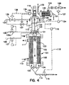
- Fig. 4 of the drawings shows the preferred embodiment for use in systems where the reactant gas can form a flammable gas mixture with the vapor above the liquid phase.
- This embodiment is particularly beneficial in the oxidation of organic chemicals with pure oxygen.
- the oxygen is injected below the liquid surface and the flow pattern is the same as that described in the embodiment above.
- a gas containment baffle is used to direct the gas flow from the top of the heat exchanger tubes back into the draft tube suction zone. Nitrogen or other inert gas is passed through the gas space above the reactor to insure that any oxygen that escapes from under the gas containment baffle is diluted to a concentration below 5%.
- This arrangement is a novel and advantageous modification of a conventional LOR reactor system having enhanced heat transfer capability to make the LOR system suitable for highly exothermic reactions.
- vertical shell and tube heat exchanger reactor 101 has hollow draft tube 102 positioned in the center thereof. Impeller means 103 are positioned within said draft tube 102, and are adapted to recirculate liquid reactant downward through the draft tube into bottom mixing chamber 104, and upward through heat exchanger tubes 105.
- An organic liquid feed is passed through feed line 106 containing flow control means 107 into upper portion 108 of reactor 101.
- An oxygen feed line 109 having flow control means 109a is used to pass oxygen or an oxygen-containing gas into said upper portion 108.
- Cooling water is passed to reactor 101 through inlet 110, and is withdrawn through outlet 111. The organic liquid feed is caused to rise upward into upper chamber 112 so as to establish liquid level 113 therein.
- Liquid level control means is in communication with measuring means at upper chamber 112 to receive input signal 117 as to the liquid level in the reactor, and to send output signal 118 to flow control means 115 so as to maintain the desired liquid level 113.
- Drive motor 119 is connected to drive shaft 120, adapted to drive impeller means 103.
- Upper baffle means 121 and lower baffle means 122 are provided to facilitate the desired recirculation of liquid downward in hollow draft tube 102 and upward in said tubes 105.
- gas containment baffle 123 is positioned in the upper portion of reactor 101 above upper baffle 121. While maintaining fluid communication between the liquid in reactor 101 and the liquid in upper chamber 112, said gas containment baffle 123 serves to minimize undesired flow of unreacted gas into said upper chamber 112 to liquid level 113 and the overhead gas phase.
- back pressure control means are provided to receive an input signal 125 as to the pressure in the gas phase 126 in upper chamber 112 and to send output signal 127 to flow control means 128 in gas discharge line 129, which contains condenser 130 to which cooling water is added through line 131 and from which cooling water is withdrawn through line 132.
- gas discharge line 129 which contains condenser 130 to which cooling water is added through line 131 and from which cooling water is withdrawn through line 132.
- nitrogen or other inert gas purge line 133 is used to introduce purge gas to gas phase 126 in upper chamber 112.
- Oxygen analyzer 134 is adapted to receive input signals as to the oxygen concentration in said gas phase 126 and to send output signals 136 to normal purge flow control means 137 and to send output signals 138 to emergency flow control means 139 to enable additional quantities of purge gas to flow to said gas phase 136 in upper chamber 112, if needed.
- Oxo acids i.e. aliphatic acids produced by the oxidation of the corresponding aldehydes
- much higher liquid circulation velocities, and therefore much higher heat transfer coefficients are achieved using the reactor system of the invention relative to gas lift shell and tube bubble column reactors.
- Oxygen was used in the reactor system of the invention to improve selectivity in the oxidation of Oxo aldehydes to the corresponding acids.
- oxygen the partial pressure of oxygen in the oxygen containing gas bubbles within the oxidation reactor is significantly greater than the inherently limited oxygen partial pressure in air. Consequently, the driving force for mass transfer is greater, and the likelihood of oxygen starved conditions which cause by-product formation is lower, with oxygen.
- the subject reactor of the invention is a well mixed stirred tank reactor system, consequently oxygen bubbles are uniformly distributed throughout the liquid.
- said reactor there are no zones that are oxygen starved due to poor gas liquid contacting.
- the requirement that the gas bubbles have a concentration of 5% or less does not apply. Consequently, depending on the vapor pressure of the liquid which acts as a diluent, the average oxygen concentration in the gas bubbles is much higher than it is in a conventional reactor with air. In systems with a very low liquid vapor pressure, the average oxygen concentration can approach 95% or higher. This compares favorably to the average 5% oxygen concentration in a conventional air based stirred tank reactor and to the average of 13% in a bubble column reactor.
- the overall higher mass transfer rate gives rise to improved oxygen mass transfer which increases the amount of oxygen available for reaction in the liquid phase and thereby reduces selectivity losses that are associated with oxygen starved conditions.
- the overall higher mass transfer rate also allows for operation at lower temperature and pressure than in conventional air based reaction systems. In particular, the operation at lower temperature further reduces by-product formation and increases selectivity.
- a preferred practice of the invention is to use a shell and tube heat exchanger with a draft tube in the center as shown in Figure 4.
- the heat load on the system is determined from the heat of reaction, the desired volumetric reaction rate and the reactor volume as shown in Equation 1. Fixing the reaction rate generally fixes the reaction temperature and pressure as well. Once the heat load, the reaction temperature and pressure are known, standard methods are used to determine U the overall heat transfer coefficient, A the required heat transfer area, and ⁇ T the temperature difference. These procedures are described below.
- a mixing impeller/pump is chosen based on power input criteria which is required for adequate reactant mixing, and flow criteria for liquid and gas circulation. These criteria are well known to those who routinely design mixing and heat exchange equipment. For gas liquid mixing systems, the power required is usually about 5 HP/1000 gallons of liquid, but this number can vary considerably depending on the reaction system.
- the flow criteria are two fold. First, it is desirable to maximize flow velocity through the heat transfer tubes in order to maximize the heat transfer coefficient U. However, pressure drop through the tubes increases as the velocity squared. Thus, there is an optimum velocity for a given system.
- the second pumping criteria which is important in gas liquid systems, is that the liquid velocity within the draft tube must be maintained above a minimum of 0.3 m/s (1 ft/s), but preferably above 0.76 m/s (2.5 ft/s) in order to insure that the gas is drawn downward through the draft tube.
- the size and speed of the impeller are chosen on the basis of the required mixing power and reactor volume. This fixes the pumping characteristics for the impeller including the flow versus head curve.
- the heat transfer area A is estimated from Equation 2 using an estimated U. Once A and the flow are estimated, the geometry of the system can readily be determined.
- the design objective is to maximize the ratio of A/V and thereby maximize the volumetric heat transfer capacity, which is turn maximizes reactor productivity.
- small diameter heat exchanger tubes are desired.
- pressure drop within the tubes increases.
- the heat exchanger tube diameter, number of tubes and tube length are varied to give the required A and acceptable values for pressure drop.
- 2.54 cm or 1.90 cm (1" or 3/4") diameter heat transfer tubes are optimum.
- the draft tube diameter is fixed by the diameter of the mixing impeller.
- the heat transfer tubes are arranged in a standard triangular pitch around the draft tube. A triangular pitch is preferred because it gives a higher A/V than either a square pitch or a radial layout.
- the upper head geometry depends on which reactor configuration is used.
- the main design constraint is to insure that the flow pattern across the top of the heat exchanger tubes is symmetric so as to provide an even flow distribution in the tubes. This is accomplished by using a conical outer shell in conjunction with a flared conical draft tube inlet section. This symmetric conical arrangement insures that the flow exiting the tubes accelerates gradually and uniformly such that the impeller suction draws from all of the tubes at an equal rate.
- the reactant gas In the cases where the reactant gas is injected below the liquid surface, passes once through the reactor and the unreacted gas is vented as waste gas, the waste gas must be prevented from being entrained in the draft tube suction flow.
- the symmetric conical arrangement described above is also necessary. In this case, the exit of the symmetric cone arrangement must be positioned such that the flow path from the top of the cone to the draft tube suction is long enough for the bubbles to disengage from the liquid before the liquid enters the draft tube.
- the bottom mixing chamber is made from a conical or dished head of the same diameter as the heat exchanger tubesheet.
- a conical head is shown in the drawings. The volume of this head can be adjusted so the total reactor volume matches the desired reactor volume.
- a cross baffle is used in the lower head to help insure even flow distribution across the heat exchanger tubes.
- the cross baffle serves to segment the discharge flow from the bottom of the draft tube into four equal parts which are directed in the radial direction.
- the mixing impeller is positioned in the top of the draft tube so as to (1) induce the vortex action to draw gas down into the liquid phase, or (2) disperse gas which is fed under the liquid surface such as when the reactant gas forms a flammable vapor mixture with the liquid.
- putting the pump near the top of the draft tube and introducing the gas near the top of the draft tube insure that reactant gas is circulated throughout the reactor volume. Gas could be introduced into the bottom of the reactor in these cases but the gas would follow the upflow through the heat exchanger tubes and exit into the gas space above.
- the draft tube would remain ungased which would defeat one of the advantages of this system, namely the uniform distribution of gas throughout the reaction volume.
- the mixing impeller/pump can be placed in either the top of the draft tube or the bottom.
- the primary function of the impeller is to pump liquid so its position is not critical.
- the gas containment baffle serves to direct unreacted gas into the draft tube where the gas is drawn downward by the liquid flow. Hence in this case, putting the impeller/pump in the bottom of the reactor does not prevent gas from being distributed uniformly throughout the reactor.
- the mixing impeller/pump can be any axial flow device such as a marine propeller or a fluid foil impeller such as the Lightnin A-315.
- the preferred embodiment for gas liquid reactor systems is the double helical impeller described by Litz et al. in U.S. 4,900,480.
- the reactor was operated in the manner of an LOR (Liquid Organic Reactor) system as in said Litz et al, U.S. 4,900,480 disclosure.
- the gas space of the reactor above the gas containment baffle was continuously inerted with nitrogen to maintain the oxygen concentration in the gas space in a safe range.
- the 1060l (280 gallon) demonstration reactor was run in parallel with a train of air sparged gas lift shell and tube bubble column reactors operated in series.
- the advantages of the new reactor system over the existing technology are shown in the Table below.
- the demonstration reactor was run at the same volumetric reaction rate as the average of the air based reactors.
- the reaction efficiency is defined as the product of the fractional conversion of aldehyde and the selectivity of converted aldehyde to acid.
- the temperature and pressure variations are given as a range because the conventional reactors operate at different temperatures and pressures. The highest temperature is maintained in the reactor with the highest reaction rate in order to maintain the reaction rate and maintain a high ⁇ T driving force for heat transfer.
- the reactor system of the invention gave an overall reaction efficiency which was 2.5% higher in a single reactor than was achieved in a train of three conventional reactors operated in series. Furthermore, the operating conditions were much less severe.
- the subject reactor operated at from 8°C to as much as 43°C lower in temperature, and from 30 psig to 50 psig lower in pressure than the conventional reactors.
- the lower temperature operation was made practical by the improved heat transfer performance of the system.
- the temperature driving force ⁇ T can be reduced as U is increased due to higher tube side flow velocities resulting from forced circulation. Also, since the reactor was configured as an oxygen based LOR the flow rate of waste gas was reduced to only 36% of the air reactors on a reactor volume equivalent basis.
- Figures 5a-5f disclose additional improvements to an LOR, in paticular the LOR disclosed herein, as follows.
- Fig. 5a illustrates the vessel 205 and the containment baffle 201.
- Containment baffle 201 generally includes all the features illustrated in Fig. 5a except for the vessel 205, mounting ring 206 and impeller shaft 212.
- the containment baffle includes cross baffle 208.
- the cross baffles 208 in straighten the downward flow of liquid into the draft tube (not shown, but corresponding to Ref. No. 2 in Fig. 1). Note that cross baffles 208 correspond to baffles 21 in Fig. 1.
- the separation weir 207 also part of the containment baffle) provides a tortuous path for the liquid to allow entrained gas bubbles to disengage.
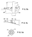
- Figs. 5b and 5d illustrates a bearing support 210 and bearing 211 to provide stability to the impeller shaft and to prevent significant cross contamination of the upper (cooler) and lower (warmer) portions of the reactor contents.
- the bearing support and bearing are part of the containment baffle.
- the containment baffle 201 also provides the lower support of the impeller shaft 212 (See Fig. 5b). Rather than having a separate structure, the containment baffle has the strength to act as shaft support and to hold the bearing support 210 and bearing 211.
- the bearing material may preferably be TEFLON@.
- Adjustable vent gates are particularly illustrated in Fig. 5c.
- adjustable gate 202 is adjusted by the gate adjustment mechanism 204, and held in place by gate holder 203.
- These gates 202 allow the gas containment baffle 201 to be adjusted and optimized to the process. It controls the openings between the upper and lower vessel section (e.g. the quiescent zone and the active zones, respectively)
- the invention also includes bearing lubrication and cooling.
- Heat the amount of which is difficult to control, can build up in the steady bearing.
- lubricant e.g. an amount insignificant enough so as not to contaminate the system
- recirculated liquid end product from the reactor preferably recirculated liquid end product from the reactor, through the impeller steady bearing in order to lubricate and cool it.
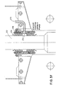
- Figures 5e and 5f are magnified views analogous to Fig. 5b (but illustrating the cooling means).
- a spiral groove 213, and cut out area 214 can be incorporated into bearing 211 in order to allow lubricant to cool the impeller shaft 212.
- the rotation of the shaft 212 creates suction such that the product is circulated from the top of the bearing to the bottom, via the spiral groove 213.
- the liquid end product forced, via the use of an external pump (not shown) via line 215, into cavity 214 of steady bearing 211 in order to cool the impeller shaft 212.
- the coolant flows out of the bearing 211 (between the bearing 211 and shaft 212) as indicated by the arrows.
- a recirculated portion of liquid end product is a preferred lubricant so as not to contaminate the reactor contents.
- the end product may be removed as a side-stream from the product discharge line (See Figure 1, Ref. No. 14), cooled, circulated through external pumping means (not shown), and fed into the bearing via line 215.
- lubricant/coolant is an important consideration.
- the amount must be large enough so as to provide effective cooling of the bearing, but small enough so that any contamination of reactor contents is insignificant.
- the amount should be small enough so as to minimize any cross contamination of the upper (cooler) and lower (warmer) reactor contents such that any effect on the heat and mass transfer efficiencies obtained through the use of the disclosed/inventive reactor (as explained elsewhere in the application) are insignificant.
- Those skilled in the art will recognize how to determine this amount and that it is dependent upon the exothermic characteristics of the particular reaction occurring in the reactor.
- the reactor system of the invention is a highly desirable advance in the art, enabling enhanced heat and mass transfer to be achieved in exothermic reactor systems.
- the volumetric reactor productivity can thus be maximized.
- Selectivity losses associated with oxygen starved conditions are also desirably reduced.
- the overall high mass transfer rate which enables operation at lower temperature and pressure, advantageously reduces by-product formation and thus increases selectivity.
- the reactor system of the invention provides an improvement desired in the art for liquid- liquid, gas-liquid and gas-liquid-solid reaction systems that are heat and mass transfer limited, enhancing productivity and selectivity performance of operations carried out therein.
Landscapes
- Chemical & Material Sciences (AREA)
- Organic Chemistry (AREA)
- Chemical Kinetics & Catalysis (AREA)
- Engineering & Computer Science (AREA)
- Oil, Petroleum & Natural Gas (AREA)
- Combustion & Propulsion (AREA)
- Organic Low-Molecular-Weight Compounds And Preparation Thereof (AREA)
- Physical Or Chemical Processes And Apparatus (AREA)
- Exposure Of Semiconductors, Excluding Electron Or Ion Beam Exposure (AREA)
- Prostheses (AREA)
- Polymerisation Methods In General (AREA)
Claims (2)
- Système de réacteur pour la conduite de réactions exothermiques d'un premier corps réactionnel liquide et d'un second corps réactionnel gazeux ou liquide afin de produire un produit final liquide, ledit système comportant:dans lequel ledit palier est refroidi par l'utilisation dudit produit final qui a été mis en circulation à travers ledit palier.(a) une cuve de réacteur;(b) un organe d'impulsion de mélange supporté par un palier et dirigé vers l'intérieur de la cuve du réacteur;
- Procédé de production d'acides aliphatiques, ledit procédé comprenant :(a) l'utilisation d'un réacteur comprenant ce qui suit:(i) une cuve de réacteur;(ii) un organe d'impulsion de mélange supporté par un palier et dirigé vers l'intérieur de la cuve du réacteur;(b) l'introduction d'un corps réactionnel à aldéhyde liquide dans ladite cuve du réacteur;(c) l'oxydation dudit corps réactionnel à aldéhyde liquide pour former un acide aliphatique;(d) la récupération d'une première portion dudit produit constitué d'acide aliphatique;(e) la recirculation d'une seconde portion dudit produit constitué d'acide aliphatique à travers ledit palier afin de refroidir ledit palier.
Applications Claiming Priority (2)
| Application Number | Priority Date | Filing Date | Title |
|---|---|---|---|
| US09/120,728 US6084125A (en) | 1996-02-27 | 1998-07-23 | Process for producing aliphatic acids using a reactor system having a shell and a tube reactor configuration to force circulation of reaction liquid |
| US120728 | 1998-07-23 |
Publications (3)
| Publication Number | Publication Date |
|---|---|
| EP0974395A2 EP0974395A2 (fr) | 2000-01-26 |
| EP0974395A3 EP0974395A3 (fr) | 2000-08-30 |
| EP0974395B1 true EP0974395B1 (fr) | 2004-02-18 |
Family
ID=22392192
Family Applications (1)
| Application Number | Title | Priority Date | Filing Date |
|---|---|---|---|
| EP99114419A Expired - Lifetime EP0974395B1 (fr) | 1998-07-23 | 1999-07-22 | Système de réacteur |
Country Status (12)
| Country | Link |
|---|---|
| US (1) | US6084125A (fr) |
| EP (1) | EP0974395B1 (fr) |
| KR (1) | KR100400895B1 (fr) |
| CN (1) | CN1121260C (fr) |
| AT (1) | ATE259673T1 (fr) |
| BR (1) | BR9902892A (fr) |
| DE (1) | DE69914835T2 (fr) |
| ES (1) | ES2214775T3 (fr) |
| ID (1) | ID23635A (fr) |
| IL (1) | IL131038A0 (fr) |
| MY (1) | MY120257A (fr) |
| PT (1) | PT974395E (fr) |
Families Citing this family (38)
| Publication number | Priority date | Publication date | Assignee | Title |
|---|---|---|---|---|
| IN237581B (fr) | 2002-02-27 | 2010-01-01 | Basf Ag | |
| US7572936B2 (en) | 2004-09-02 | 2009-08-11 | Eastman Chemical Company | Optimized liquid-phase oxidation |
| US7582793B2 (en) | 2004-09-02 | 2009-09-01 | Eastman Chemical Company | Optimized liquid-phase oxidation |
| CN101023046B (zh) * | 2004-09-02 | 2019-01-18 | 奇派特石化有限公司 | 优化的液相氧化 |
| US7399882B2 (en) | 2004-09-02 | 2008-07-15 | Eastman Chemical Company | Optimized liquid-phase oxidation |
| US7507857B2 (en) | 2004-09-02 | 2009-03-24 | Eastman Chemical Company | Optimized liquid-phase oxidation |
| US7572932B2 (en) | 2004-09-02 | 2009-08-11 | Eastman Chemical Company | Optimized liquid-phase oxidation |
| US7568361B2 (en) * | 2004-09-02 | 2009-08-04 | Eastman Chemical Company | Optimized liquid-phase oxidation |
| US7608732B2 (en) | 2005-03-08 | 2009-10-27 | Eastman Chemical Company | Optimized liquid-phase oxidation |
| US7692037B2 (en) | 2004-09-02 | 2010-04-06 | Eastman Chemical Company | Optimized liquid-phase oxidation |
| US7608733B2 (en) | 2004-09-02 | 2009-10-27 | Eastman Chemical Company | Optimized liquid-phase oxidation |
| US7910769B2 (en) | 2004-09-02 | 2011-03-22 | Eastman Chemical Company | Optimized liquid-phase oxidation |
| US7741515B2 (en) * | 2004-09-02 | 2010-06-22 | Eastman Chemical Company | Optimized liquid-phase oxidation |
| US7692036B2 (en) | 2004-11-29 | 2010-04-06 | Eastman Chemical Company | Optimized liquid-phase oxidation |
| US7504535B2 (en) | 2004-09-02 | 2009-03-17 | Eastman Chemical Company | Optimized liquid-phase oxidation |
| US7482482B2 (en) | 2004-09-02 | 2009-01-27 | Eastman Chemical Company | Optimized liquid-phase oxidation |
| US7381836B2 (en) | 2004-09-02 | 2008-06-03 | Eastman Chemical Company | Optimized liquid-phase oxidation |
| US7495125B2 (en) | 2004-09-02 | 2009-02-24 | Eastman Chemical Company | Optimized liquid-phase oxidation |
| US7683210B2 (en) | 2004-09-02 | 2010-03-23 | Eastman Chemical Company | Optimized liquid-phase oxidation |
| US7589231B2 (en) | 2004-09-02 | 2009-09-15 | Eastman Chemical Company | Optimized liquid-phase oxidation |
| US7884232B2 (en) | 2005-06-16 | 2011-02-08 | Eastman Chemical Company | Optimized liquid-phase oxidation |
| US7355068B2 (en) | 2006-01-04 | 2008-04-08 | Eastman Chemical Company | Oxidation system with internal secondary reactor |
| TWI367878B (en) * | 2008-01-09 | 2012-07-11 | Uop Llc | Process for separating diisopropylbenzene (dipb) and triisopropylbenzene (tipb) from a feed comprising dipb, tipb, and polyalkylate heavies |
| EP2179788B9 (fr) * | 2008-10-24 | 2012-02-08 | Biazzi Sa | Appareillage à cuve d'agitation |
| WO2010107881A1 (fr) | 2009-03-17 | 2010-09-23 | Dow Global Technologies, Inc. | Appareil échangeur de chaleur à enveloppe et tube à écoulement pulsé séquentiellement côté tube, système et procédé |
| WO2013157798A1 (fr) * | 2012-04-16 | 2013-10-24 | 목포대학교산학협력단 | Réacteur sous-critique et procédé de réaction sous-critique faisant appel à ce dernier |
| CN103521158B (zh) * | 2013-10-29 | 2015-12-02 | 万华化学集团股份有限公司 | 一种连续化制备丁二腈的方法 |
| US9180436B1 (en) | 2013-11-19 | 2015-11-10 | Emerging Fuels Technology, Inc. | Optimized fischer-tropsch catalyst |
| US9358526B2 (en) | 2013-11-19 | 2016-06-07 | Emerging Fuels Technology, Inc. | Optimized fischer-tropsch catalyst |
| WO2015087353A1 (fr) | 2013-12-12 | 2015-06-18 | Council Of Scientific & Industrial Research | Réacteur doublé de verre continu de type tube dans tube |
| CN104613091B (zh) * | 2015-01-28 | 2018-03-27 | 沈阳世润重工有限公司 | 一种应用于增速机的巴氏合金滑动轴瓦润滑结构 |
| CN104705423B (zh) * | 2015-03-27 | 2017-11-28 | 扬州奥巴玛科技发展有限公司 | 一种尾热回收炼油锅 |
| WO2016169771A1 (fr) * | 2015-04-23 | 2016-10-27 | Uhde Inventa-Fischer Gmbh | Réacteur ainsi que procédé pour la polymérisation de lactide |
| CN105176697A (zh) * | 2015-08-17 | 2015-12-23 | 龙岩卓越新能源股份有限公司 | 废油脂制备生物柴油的连续酯化塔装置 |
| CN114425292A (zh) * | 2017-04-20 | 2022-05-03 | 辽宁抚清助剂有限公司 | 异丙苯过氧化氢常压管式反应器及生产工艺 |
| CN111167385B (zh) * | 2020-01-10 | 2022-03-01 | 天津大学 | 利用醛原料和空气制备酸的喷射型气液反应器 |
| EP3995205A1 (fr) * | 2020-11-10 | 2022-05-11 | Universidad de Castilla La Mancha | Capture de co2 utilisant des médias alcalines pour la préparation de carbonate de sodium |
| CN116239510B (zh) * | 2021-12-07 | 2024-10-29 | 万华化学集团股份有限公司 | 一种连续生产维生素a醋酸酯的方法及装置 |
Family Cites Families (14)
| Publication number | Priority date | Publication date | Assignee | Title |
|---|---|---|---|---|
| US2134571A (en) * | 1934-07-27 | 1938-10-25 | American Lurgi Corp | Device for the hydrogenation of vegetable or animal oils or fats, fatty acids, or the like |
| US2194666A (en) * | 1935-10-31 | 1940-03-26 | Meissner Josef | Nitration of aromatic hydrocarbons |
| US3028227A (en) * | 1956-09-04 | 1962-04-03 | Ballestra Mario | Apparatus for continuously effecting sulphonation, nitration, and like strongly-exothermic reactions |
| DE1208734B (de) * | 1963-05-27 | 1966-01-13 | Studiengesellschaft Kohle Mbh | Ruehr-, Misch- und Dispergiervorrichtung |
| US4449828A (en) * | 1980-10-27 | 1984-05-22 | Ashland Oil, Inc. | Mixing apparatus |
| DE3423945A1 (de) * | 1984-06-29 | 1986-01-09 | Henkel KGaA, 4000 Düsseldorf | Verfahren und vorrichtung zur kontinuierlichen hydrothermalen herstellung von natriumsilikatloesungen |
| JPS6269976A (ja) * | 1985-09-24 | 1987-03-31 | Kansai Kagaku Kikai Seisaku Kk | 酒石を除去する方法及び装置 |
| US4900480A (en) * | 1986-10-21 | 1990-02-13 | Union Carbide Corporation | Gas-liquid mixing |
| US4919849A (en) * | 1988-12-23 | 1990-04-24 | Union Carbide Industrial Gases Technology Corporation | Gas-liquid mixing process and apparatus |
| EP0565602B1 (fr) * | 1991-01-07 | 1996-04-24 | Comalco Aluminium, Ltd. | Appareil de refroidissement ou chauffage d'une suspension dans une chaudière |
| US5248613A (en) * | 1991-07-08 | 1993-09-28 | Roubicek Rudolf V | Nonhomogeneous centrifugal film bioreactor |
| GB9307225D0 (en) * | 1993-04-03 | 1993-05-26 | Atomic Energy Authority Uk | Processing vessel |
| US5451349A (en) * | 1994-08-08 | 1995-09-19 | Praxair Technology, Inc. | Advanced gas control in gas-liquid mixing systems |
| US5846498A (en) * | 1996-02-27 | 1998-12-08 | Praxair Technology, Inc. | Reactor system |
-
1998
- 1998-07-23 US US09/120,728 patent/US6084125A/en not_active Expired - Fee Related
-
1999
- 1999-07-19 ID IDP990680A patent/ID23635A/id unknown
- 1999-07-22 ES ES99114419T patent/ES2214775T3/es not_active Expired - Lifetime
- 1999-07-22 EP EP99114419A patent/EP0974395B1/fr not_active Expired - Lifetime
- 1999-07-22 DE DE69914835T patent/DE69914835T2/de not_active Expired - Fee Related
- 1999-07-22 CN CN99110525A patent/CN1121260C/zh not_active Expired - Fee Related
- 1999-07-22 AT AT99114419T patent/ATE259673T1/de not_active IP Right Cessation
- 1999-07-22 MY MYPI99003090A patent/MY120257A/en unknown
- 1999-07-22 BR BR9902892-1A patent/BR9902892A/pt not_active IP Right Cessation
- 1999-07-22 IL IL13103899A patent/IL131038A0/xx unknown
- 1999-07-22 PT PT99114419T patent/PT974395E/pt unknown
- 1999-07-22 KR KR10-1999-0029714A patent/KR100400895B1/ko not_active Expired - Fee Related
Also Published As
| Publication number | Publication date |
|---|---|
| KR20000011888A (ko) | 2000-02-25 |
| CN1121260C (zh) | 2003-09-17 |
| PT974395E (pt) | 2004-05-31 |
| CN1243034A (zh) | 2000-02-02 |
| ES2214775T3 (es) | 2004-09-16 |
| EP0974395A2 (fr) | 2000-01-26 |
| ATE259673T1 (de) | 2004-03-15 |
| MY120257A (en) | 2005-09-30 |
| US6084125A (en) | 2000-07-04 |
| ID23635A (id) | 2000-05-04 |
| IL131038A0 (en) | 2001-01-28 |
| BR9902892A (pt) | 2000-05-09 |
| KR100400895B1 (ko) | 2003-10-08 |
| EP0974395A3 (fr) | 2000-08-30 |
| DE69914835T2 (de) | 2004-12-30 |
| DE69914835D1 (de) | 2004-03-25 |
Similar Documents
| Publication | Publication Date | Title |
|---|---|---|
| EP0974395B1 (fr) | Système de réacteur | |
| CA2278400C (fr) | Filiere de reacteurs amelioree | |
| EP0792683B1 (fr) | Système de réacteur à enveloppe et faisceaux de tubes | |
| US4900480A (en) | Gas-liquid mixing | |
| EP1073621B1 (fr) | Preparation d'acides organiques | |
| KR920000042B1 (ko) | 기체와 액체의 혼합방법 및 장치 | |
| US5523474A (en) | Terephthalic acid production using evaporative cooling | |
| US6838061B1 (en) | Reactor for carrying out gas-liquid, liquid, liquid-liquid or gas-liquid-solid chemical reactions | |
| US5696285A (en) | Production of terephthalic acid with excellent optical properties through the use of pure or nearly pure oxygen as the oxidant in p-xylene oxidation | |
| US3534090A (en) | Hydrocarbon oxidation | |
| CS217968B2 (en) | Reactor for oxydation of the alkylaromate in the liquid phase under utilization of tha gs containing the oxygen | |
| JP2005161313A (ja) | 有機化学物質の増進された酸化 | |
| US5110508A (en) | Process and apparatus for making a heat-sensitive material | |
| US5243083A (en) | Thermosyphonic reaction of oxygen with isobutane and reactor | |
| MXPA99006839A (en) | Best reactor system | |
| CA2198513A1 (fr) | Procede ameliore pour la production d'acides organiques | |
| MXPA00010181A (en) | Preparation of organic acids |
Legal Events
| Date | Code | Title | Description |
|---|---|---|---|
| PUAI | Public reference made under article 153(3) epc to a published international application that has entered the european phase |
Free format text: ORIGINAL CODE: 0009012 |
|
| AK | Designated contracting states |
Kind code of ref document: A2 Designated state(s): AT BE CH CY DE DK ES FI FR GB GR IE IT LI LU MC NL PT SE |
|
| AX | Request for extension of the european patent |
Free format text: AL;LT;LV;MK;RO;SI |
|
| PUAL | Search report despatched |
Free format text: ORIGINAL CODE: 0009013 |
|
| RIC1 | Information provided on ipc code assigned before grant |
Free format text: 7B 01J 19/18 A, 7B 01J 19/00 B, 7B 01J 14/00 B, 7B 01J 10/00 B, 7B 01F 15/06 B, 7C 07C 51/235 B, 7F 16C 37/00 B |
|
| AK | Designated contracting states |
Kind code of ref document: A3 Designated state(s): AT BE CH CY DE DK ES FI FR GB GR IE IT LI LU MC NL PT SE |
|
| AX | Request for extension of the european patent |
Free format text: AL;LT;LV;MK;RO;SI |
|
| 17P | Request for examination filed |
Effective date: 20000908 |
|
| AKX | Designation fees paid |
Free format text: AT BE CH CY DE DK ES FI FR GB GR IE IT LI LU MC NL PT SE |
|
| 17Q | First examination report despatched |
Effective date: 20010822 |
|
| GRAP | Despatch of communication of intention to grant a patent |
Free format text: ORIGINAL CODE: EPIDOSNIGR1 |
|
| GRAS | Grant fee paid |
Free format text: ORIGINAL CODE: EPIDOSNIGR3 |
|
| GRAA | (expected) grant |
Free format text: ORIGINAL CODE: 0009210 |
|
| AK | Designated contracting states |
Kind code of ref document: B1 Designated state(s): AT BE CH CY DE DK ES FI FR GB GR IE IT LI LU MC NL PT SE |
|
| PG25 | Lapsed in a contracting state [announced via postgrant information from national office to epo] |
Ref country code: LI Free format text: LAPSE BECAUSE OF FAILURE TO SUBMIT A TRANSLATION OF THE DESCRIPTION OR TO PAY THE FEE WITHIN THE PRESCRIBED TIME-LIMIT Effective date: 20040218 Ref country code: FI Free format text: LAPSE BECAUSE OF FAILURE TO SUBMIT A TRANSLATION OF THE DESCRIPTION OR TO PAY THE FEE WITHIN THE PRESCRIBED TIME-LIMIT Effective date: 20040218 Ref country code: CY Free format text: LAPSE BECAUSE OF FAILURE TO SUBMIT A TRANSLATION OF THE DESCRIPTION OR TO PAY THE FEE WITHIN THE PRESCRIBED TIME-LIMIT Effective date: 20040218 Ref country code: CH Free format text: LAPSE BECAUSE OF FAILURE TO SUBMIT A TRANSLATION OF THE DESCRIPTION OR TO PAY THE FEE WITHIN THE PRESCRIBED TIME-LIMIT Effective date: 20040218 Ref country code: AT Free format text: LAPSE BECAUSE OF FAILURE TO SUBMIT A TRANSLATION OF THE DESCRIPTION OR TO PAY THE FEE WITHIN THE PRESCRIBED TIME-LIMIT Effective date: 20040218 |
|
| REG | Reference to a national code |
Ref country code: GB Ref legal event code: FG4D |
|
| REG | Reference to a national code |
Ref country code: CH Ref legal event code: EP |
|
| REG | Reference to a national code |
Ref country code: IE Ref legal event code: FG4D |
|
| REF | Corresponds to: |
Ref document number: 69914835 Country of ref document: DE Date of ref document: 20040325 Kind code of ref document: P |
|
| PG25 | Lapsed in a contracting state [announced via postgrant information from national office to epo] |
Ref country code: SE Free format text: LAPSE BECAUSE OF FAILURE TO SUBMIT A TRANSLATION OF THE DESCRIPTION OR TO PAY THE FEE WITHIN THE PRESCRIBED TIME-LIMIT Effective date: 20040518 Ref country code: GR Free format text: LAPSE BECAUSE OF FAILURE TO SUBMIT A TRANSLATION OF THE DESCRIPTION OR TO PAY THE FEE WITHIN THE PRESCRIBED TIME-LIMIT Effective date: 20040518 Ref country code: DK Free format text: LAPSE BECAUSE OF FAILURE TO SUBMIT A TRANSLATION OF THE DESCRIPTION OR TO PAY THE FEE WITHIN THE PRESCRIBED TIME-LIMIT Effective date: 20040518 |
|
| REG | Reference to a national code |
Ref country code: PT Ref legal event code: SC4A Free format text: AVAILABILITY OF NATIONAL TRANSLATION Effective date: 20040308 |
|
| PGFP | Annual fee paid to national office [announced via postgrant information from national office to epo] |
Ref country code: MC Payment date: 20040701 Year of fee payment: 6 |
|
| PGFP | Annual fee paid to national office [announced via postgrant information from national office to epo] |
Ref country code: IE Payment date: 20040723 Year of fee payment: 6 |
|
| PGFP | Annual fee paid to national office [announced via postgrant information from national office to epo] |
Ref country code: LU Payment date: 20040730 Year of fee payment: 6 |
|
| REG | Reference to a national code |
Ref country code: CH Ref legal event code: PL |
|
| REG | Reference to a national code |
Ref country code: ES Ref legal event code: FG2A Ref document number: 2214775 Country of ref document: ES Kind code of ref document: T3 |
|
| ET | Fr: translation filed | ||
| PLBE | No opposition filed within time limit |
Free format text: ORIGINAL CODE: 0009261 |
|
| STAA | Information on the status of an ep patent application or granted ep patent |
Free format text: STATUS: NO OPPOSITION FILED WITHIN TIME LIMIT |
|
| 26N | No opposition filed |
Effective date: 20041119 |
|
| PG25 | Lapsed in a contracting state [announced via postgrant information from national office to epo] |
Ref country code: LU Free format text: LAPSE BECAUSE OF NON-PAYMENT OF DUE FEES Effective date: 20050722 Ref country code: IE Free format text: LAPSE BECAUSE OF NON-PAYMENT OF DUE FEES Effective date: 20050722 |
|
| PG25 | Lapsed in a contracting state [announced via postgrant information from national office to epo] |
Ref country code: MC Free format text: LAPSE BECAUSE OF NON-PAYMENT OF DUE FEES Effective date: 20050731 |
|
| REG | Reference to a national code |
Ref country code: IE Ref legal event code: MM4A |
|
| PGFP | Annual fee paid to national office [announced via postgrant information from national office to epo] |
Ref country code: PT Payment date: 20060711 Year of fee payment: 8 |
|
| PGFP | Annual fee paid to national office [announced via postgrant information from national office to epo] |
Ref country code: FR Payment date: 20060713 Year of fee payment: 9 |
|
| PGFP | Annual fee paid to national office [announced via postgrant information from national office to epo] |
Ref country code: NL Payment date: 20060724 Year of fee payment: 8 |
|
| PGFP | Annual fee paid to national office [announced via postgrant information from national office to epo] |
Ref country code: GB Payment date: 20060726 Year of fee payment: 8 Ref country code: ES Payment date: 20060726 Year of fee payment: 8 |
|
| PGFP | Annual fee paid to national office [announced via postgrant information from national office to epo] |
Ref country code: IT Payment date: 20060731 Year of fee payment: 8 |
|
| PGFP | Annual fee paid to national office [announced via postgrant information from national office to epo] |
Ref country code: BE Payment date: 20060828 Year of fee payment: 8 |
|
| PGFP | Annual fee paid to national office [announced via postgrant information from national office to epo] |
Ref country code: DE Payment date: 20060831 Year of fee payment: 8 |
|
| BERE | Be: lapsed |
Owner name: *PRAXAIR TECHNOLOGY INC. Effective date: 20070731 |
|
| REG | Reference to a national code |
Ref country code: PT Ref legal event code: MM4A Free format text: LAPSE DUE TO NON-PAYMENT OF FEES Effective date: 20080122 |
|
| GBPC | Gb: european patent ceased through non-payment of renewal fee |
Effective date: 20070722 |
|
| NLV4 | Nl: lapsed or anulled due to non-payment of the annual fee |
Effective date: 20080201 |
|
| PG25 | Lapsed in a contracting state [announced via postgrant information from national office to epo] |
Ref country code: NL Free format text: LAPSE BECAUSE OF NON-PAYMENT OF DUE FEES Effective date: 20080201 Ref country code: DE Free format text: LAPSE BECAUSE OF NON-PAYMENT OF DUE FEES Effective date: 20080201 |
|
| PG25 | Lapsed in a contracting state [announced via postgrant information from national office to epo] |
Ref country code: PT Free format text: LAPSE BECAUSE OF NON-PAYMENT OF DUE FEES Effective date: 20080122 Ref country code: GB Free format text: LAPSE BECAUSE OF NON-PAYMENT OF DUE FEES Effective date: 20070722 |
|
| REG | Reference to a national code |
Ref country code: FR Ref legal event code: ST Effective date: 20080331 |
|
| PG25 | Lapsed in a contracting state [announced via postgrant information from national office to epo] |
Ref country code: BE Free format text: LAPSE BECAUSE OF NON-PAYMENT OF DUE FEES Effective date: 20070731 |
|
| PG25 | Lapsed in a contracting state [announced via postgrant information from national office to epo] |
Ref country code: FR Free format text: LAPSE BECAUSE OF NON-PAYMENT OF DUE FEES Effective date: 20070731 |
|
| REG | Reference to a national code |
Ref country code: ES Ref legal event code: FD2A Effective date: 20070723 |
|
| PG25 | Lapsed in a contracting state [announced via postgrant information from national office to epo] |
Ref country code: ES Free format text: LAPSE BECAUSE OF NON-PAYMENT OF DUE FEES Effective date: 20070723 |
|
| PG25 | Lapsed in a contracting state [announced via postgrant information from national office to epo] |
Ref country code: IT Free format text: LAPSE BECAUSE OF NON-PAYMENT OF DUE FEES Effective date: 20070722 |