EP0974774A1 - Speed reducing device - Google Patents
Speed reducing device Download PDFInfo
- Publication number
- EP0974774A1 EP0974774A1 EP99830460A EP99830460A EP0974774A1 EP 0974774 A1 EP0974774 A1 EP 0974774A1 EP 99830460 A EP99830460 A EP 99830460A EP 99830460 A EP99830460 A EP 99830460A EP 0974774 A1 EP0974774 A1 EP 0974774A1
- Authority
- EP
- European Patent Office
- Prior art keywords
- gear
- casing
- wall
- cover
- gears
- Prior art date
- Legal status (The legal status is an assumption and is not a legal conclusion. Google has not performed a legal analysis and makes no representation as to the accuracy of the status listed.)
- Granted
Links
- 239000003638 chemical reducing agent Substances 0.000 claims description 63
- 230000000295 complement effect Effects 0.000 claims description 2
- 238000004519 manufacturing process Methods 0.000 description 4
- 238000007789 sealing Methods 0.000 description 4
- 230000005540 biological transmission Effects 0.000 description 3
- 239000012530 fluid Substances 0.000 description 3
- 230000001050 lubricating effect Effects 0.000 description 3
- 238000005266 casting Methods 0.000 description 1
- 230000008878 coupling Effects 0.000 description 1
- 238000010168 coupling process Methods 0.000 description 1
- 238000005859 coupling reaction Methods 0.000 description 1
- 239000000314 lubricant Substances 0.000 description 1
- 238000012986 modification Methods 0.000 description 1
- 230000004048 modification Effects 0.000 description 1
- 239000000126 substance Substances 0.000 description 1
Images


Classifications
-
- F—MECHANICAL ENGINEERING; LIGHTING; HEATING; WEAPONS; BLASTING
- F16—ENGINEERING ELEMENTS AND UNITS; GENERAL MEASURES FOR PRODUCING AND MAINTAINING EFFECTIVE FUNCTIONING OF MACHINES OR INSTALLATIONS; THERMAL INSULATION IN GENERAL
- F16H—GEARING
- F16H57/00—General details of gearing
- F16H57/02—Gearboxes; Mounting gearing therein
- F16H57/033—Series gearboxes, e.g. gearboxes based on the same design being available in different sizes or gearboxes using a combination of several standardised units
-
- F—MECHANICAL ENGINEERING; LIGHTING; HEATING; WEAPONS; BLASTING
- F16—ENGINEERING ELEMENTS AND UNITS; GENERAL MEASURES FOR PRODUCING AND MAINTAINING EFFECTIVE FUNCTIONING OF MACHINES OR INSTALLATIONS; THERMAL INSULATION IN GENERAL
- F16H—GEARING
- F16H1/00—Toothed gearings for conveying rotary motion
- F16H1/02—Toothed gearings for conveying rotary motion without gears having orbital motion
- F16H1/20—Toothed gearings for conveying rotary motion without gears having orbital motion involving more than two intermeshing members
-
- Y—GENERAL TAGGING OF NEW TECHNOLOGICAL DEVELOPMENTS; GENERAL TAGGING OF CROSS-SECTIONAL TECHNOLOGIES SPANNING OVER SEVERAL SECTIONS OF THE IPC; TECHNICAL SUBJECTS COVERED BY FORMER USPC CROSS-REFERENCE ART COLLECTIONS [XRACs] AND DIGESTS
- Y10—TECHNICAL SUBJECTS COVERED BY FORMER USPC
- Y10T—TECHNICAL SUBJECTS COVERED BY FORMER US CLASSIFICATION
- Y10T74/00—Machine element or mechanism
- Y10T74/21—Elements
- Y10T74/2186—Gear casings
Definitions
- the present invention relates to a speed varying device.
- speed reducers are mechanical devices provided with an input shaft and an output shaft, which are respectively connected to a motor and to a user unit and are able to drive the user unit itself with a rotatory motion presenting a lesser speed than the speed whereat the aforementioned input shaft rotates.
- Such types of reducers substantially comprise a box body for the containment of a plurality of shafts, whereon are splined gears which, in pairs, mutually transmit motion with appropriate transmission ratios and give rise to the aforementioned driving of the output shaft with lesser speed than that of the input shaft.
- the velocities of rotation of the input and, respectively, of the output shaft, as well as the value of the torque that the output shaft must transmit to the user unit, determine the choice of motor to be associated to each reducer, and oblige to provide the reducer itself with a number of gear pairs equal to or greater than two.
- a casing when there is a need to obtain a total transmission ratio whose value entails the use of a number of gear pairs greater than two, it is necessary to interpose between a casing and a cover, comprised in the aforesaid box body, an additional sector of casing, which supports at least one pair of gears to be added to those already present.
- the cover also needs to be chosen adequately as a function of the transmission ratio to be attained and of the aforementioned torque value, in order to allow coupling to the reducer a motor able to provide at its output a number of rotations per minute and a power suitable for the requirements.
- the casing is constructed in a single body, and it is fitted internally with an additional casing sector which is always present, both in the case of a reducer with two gear pairs, and in the case of a reducer with three or more gear pairs.
- additional casing sector essentially comprises a wall, provided with a number of holes or housings able to receive respective elements for supporting shafts whereon gears are splined.
- Such housings are in a sufficient number to accommodate the presence of the maximum number of gear pairs with which the reducers in question can be provided.
- the aforesaid casing is fitted with an additional casing sector of considerable constructive complexity, provided with a number of housings exceeding the number actually necessary and characterised by a needlessly high cost of manufacture.
- Such cost of manufacture is particularly considerable also due to the fact that the mechanical complex constituted by the casing and by the aforementioned additional sector is obtained by casting, using a core of considerable size due to the presence in the complex itself of ample undercuts.
- the purpose of the present invention is therefore to eliminate the drawbacks mentioned above.
- a speed reducing device characterised in that it comprises a box body (59") for housing and supporting a set number of gear pairs varying as a function of the speed variation ratio of the device itself, said gear pairs being kinematically connected to each other to transmit the motion between an input shaft and an output shaft of said speed varying device;
- said box body being defined by a casing which is always the same for any set number of said gear pairs, and presenting substantially the form of a cup-shaped body and supporting a set number of said gears kinematically connected to each other; to said casing being connectable one of at least two covers chosen according to the set number of gears present in the speed varying device; each of said two covers supporting a further set number of said gears complementary to said set number of said gears present in said casing to form said desired variation ratio of said device, and at least to one of said two covers being associated, within said box body, a wall supporting a part of said further set number of gears
- the number 1 indicates in its entirety a first type of reducer device known in the art, which comprises a box body 2 constituted by a casing 3, by an additional casing sector 4 and by a cover 5 mutually connected in pairs and in the order described above with interposition of sealing elements for the lubricating fluids not shown.
- the casing 3 is provided with a hole 6 with horizontal axis, obtained in one of its walls 7 positioned to the left in Figure 1 and housing within it two ball bearings 8 supporting with their inner rings an output shaft 9 with horizontal axis of the reducer 1, provided with an end portion projecting from the box body 2.
- On the other end of the shaft 9 is coaxially splined a gear wheel 10, which is engaged with a gear wheel 11 splined (or obtained from the same piece) in correspondence with an intermediate portion of a tree 12 with horizontal axis.
- the end of the shaft 12 positioned to the left in Figure 1 is housed inside the inner ring of a ball bearing 13 presenting its own outer ring fitted within a hole 14 obtained in an internal position of the casing 3 located below the hole 6, while, to the side of the gear wheel 11, on the shaft 12 is coaxially splined a further gear wheel 15.
- the right-side end of the shaft 12 is housed inside the inner ring of a bearing 16, whose outer ring is fitted within a hole 17 with which the aforesaid additional casing sector 4 is provided.
- Such additional casing sector 4 is further provided, above the hole 17, with a hole 18 with horizontal axis within which is fitted the inner ring of a ball bearing 19 supporting coaxially with its inner ring a median portion of a shaft 20.
- a gear wheel 21 On an end portion of such shaft 20 positioned to the left in Figure 1 is splined (or obtained from the same piece) a gear wheel 21 able to engage, in use, with the aforementioned gear wheel 15, whilst immediately to the right of the bearing 19 the shaft 20 bears splined an additional gear wheel 22.
- the right end portion of the shaft 20 is housed within the inner ring of a ball bearing 23, whose outer ring can be housed inside a cavity 24 present in the aforementioned cover 5.
- gear wheel 29 On the end of shaft 28 positioned to the left in Figure 1 is splined (or obtained from one piece) a gear wheel 29, able to co-operate, in use, with the aforementioned gear wheel 22.
- the right end of the shaft 28 is provided coaxially with a cavity 30 able to be engaged by the output shaft (not shown) of a motor that is not shown, which is connectable to a flange 31 comprised in the cover 5 by means of connecting elements constituted, for instance, by screws (not shown).
- the reducer 1 just described is provided with three pairs of gear wheels 10, 11, 15, 21 and 22, 29, and it is of the first type described in the premises to the present description.
- Figures 2 and 3 show a reducer 32 of the second type described in the premises to the present description.
- Such reducer 32 of the type with two gear pairs, comprises a box body 33 constituted by a casing 34, in turn constituted by a substantially cylindrical element 35 closed, in correspondence with its end positioned to the left in Figures 2 and 3, by a cover 36, and, in correspondence with its end positioned to the right, by a cover 37.
- the axial ends of the element 35 and the respective covers 36 and 37 are mutually connected with interposition of sealing gaskets not shown.
- the cover 36 is provided with a hole 38 with horizontal axis, housing within it a ball bearing 39 supporting with its inner ring an output shaft 40 of the reducer 32 with horizontal axis, provided with an end portion projecting from the box body 33.
- a gear wheel 41 On the other end of the shaft 40 is coaxially splined a gear wheel 41, which is engaged with a gear wheel 42 splined (or obtained from the same piece) in correspondence with an intermediate portion of a shaft 43 with horizontal axis.
- the end of the shaft 43 positioned to the left in Figures 2 and 3, is housed within the inner ring of a ball bearing 44 presenting its own outer ring fitted within a hole 45 obtained in an inner portion of the casing 34 located below the hole 38.
- a hole 49 housing the outer ring of a ball bearing 50, whose inner ring is fitted coaxially to a right end portion of the aforementioned shaft 40.
- the right end of the shaft 53 is coaxially provided with a cavity 56 able to be engaged by the output shaft of a motor not shown herein, which is connectable to a flange 57 comprised in the cover 37 by means of connecting elements constituted, for instance, by screws (not shown).
- the reducer 32 just described is provided with two reduction stages constituted by two pairs of gear wheels 41, 42 and 51, 52, and, as specified above, it is of the second type considered in the premises of the present description.
- the casing 34 of the reducer 32 is stably associated the aforesaid wall 48, better shown in the schematic Figure 7, wherein are always present, although used only in part as in the case just described, the aforementioned holes 47 and 49 and an additional ground hole 58; the hole 58 is able to house possible means for supporting a third gear pair, and, as specified above, its presence, in the case of use of only two gear pairs, entails needlessly high costs to manufacture the casing 34 and, as a result, the entire reducer 32.
- the shaft 43 passes through a ground hole, not shown in Figure 3 and obtained in a wall 48 which, perpendicularly to the axis of the shaft 40, transversely delimits an inner intermediate area of the casing 34.
- the hole through which the shaft 43 passes corresponds to the hole 58 of Figure 5 and its wall 48 corresponds to the wall 48 of Figure 2.
- the shaft 53 can coincide with the output shaft of a motor not shown, which is connectable to the flange 57 comprised in the cover 37 by means of connecting elements known in the art and not shown.
- the reducer 32 described above with reference to Figure 3 is provided with two reduction stages constituted by two pairs of gear wheels 41, 42 and 51, 52, and, as specified above, it is of the second type considered in the premises of the present description.
- Figure 4 shows the same reducer as in Figure 3, but provided with three reduction stages.
- the wall 48 is sectioned according to two different planes whereof one coincides with the section plane of Figure 3 and the other one is offset with respect to the axis of the shaft 40 towards an observer looking at Figure 4.
- This second section plane highlights that the wall 48 is provided, in addition to the aforementioned hole 49, with a further hole 111 which supports, by means of a bearing 112, the right end of an additional shaft 113.
- the shaft 113 is provided, to the right of the hole 111, with a wheel 114 which enmeshes with a second wheel 115 obtained on the shaft 43.
- the shaft 113 is driven by shaft 43 through the reduction pair constituted by the wheel 115 and by the wheel 114, and it is provided with a wheel 116 that enmeshes with the wheel 41.
- the wheel 116 and the wheel 41 constitute an additional reduction stage.
- the reducer shown in Figure 4 is thus provided with three reduction stages, constituted by the three pairs of gear wheels indicated, respectively with the numbers 51, 52, 114, 115, and 116, 41.
- the hole 111 is present both for the reducer with two reduction stages, and for the reducer with three reduction stages.
- Figured 6 and 7 respectively show two reducers 59 and 59' realised in accordance with the present invention, provided respectively with two and with three gear pairs.
- Both reducers 59 and 59' comprise a box body 59" defined by a casing 60 having the shape of a cup body with the bottom located to the left in the figures in question, and which is always the same for any type of reducer, both in the case wherein the reducer presents two reduction stages, and in the case wherein the reducer presents three reduction stages.
- the inlet of such casing 60 positioned to the right in Figures 6 and 7, is closed by a cover comprised in the box body 59" and indicated respectively, in Figures 6 and 7, with the numbers 61 and 62.
- Such covers 61 and 62 as shall become readily apparent hereafter, differ from each other.
- the casing 60 is provided with a hole 63 with horizontal axis, obtained in its wall 64 located to the left in Figures 6 and 7 and housing within it two ball bearings 65 supporting with their inner rings an output shaft 66 of the reducer 59, with horizontal axis, provided with an end portion projecting from the casing 60.
- On the other end of the shaft 66 is coaxially splined a gear wheel 67, which is engaged with a gear wheel 68 splined (or obtained from one piece) in correspondence with an intermediate portion of a shaft 69 with horizontal axis.
- the end of the shaft 69 positioned to the left in Figures 6 and 7 is housed inside the inner ring of a ball bearing 70 presenting its own outer ring fit inside a hole 71 obtained in an inner portion of the casing 60 positioned below the hole 63, whilst, to the side of the gear wheel 68, on the shaft 69 is coaxially splined a further gear wheel 72.
- the right end of the shaft 69 is housed inside the inner ring of a bearing 73, whose outer ring is fitted within a hole 74 obtained in a wall 75, 76, respectively delimiting the left side in the covers 61 and 62.
- a further hole 77 with horizontal axis within which is coaxially housed the outer ring of a ball bearing 78 whose function shall become readily apparent hereafter.
- An end of such hole 77 positioned to the right in Figure 3 communicates with an inner cavity 79 of a sleeve 80 coaxial to the hole 77 itself and presenting its left end integral with the wall 75.
- a ball bearing 81 which, in combination with the aforementioned bearing 78, supports in a rotatory manner a shaft 82 on whose end portions positioned within the casing 60 and extending leftwards in Figure 6 is splined (or obtained from the same piece) a gear wheel 83 able to co-operate with the aforementioned gear wheel 72.
- the right end of the shaft 82 is provided coaxially with a cavity 84 able to be engaged by the output shaft of a motor not shown herein, which is connectable to a flange 85, comprised in the cover 61 and connected to the right end of the sleeve 80, through connecting elements constituted, for instance, by screws 86.
- the aforementioned wall 76 partially delimits the left flank of the cover 62 oriented towards the casing 60, and it is provided, in correspondence with its portion overlying the hole 74, with an additional hole 87 with horizontal axis, within which is coaxially housed the outer ring of a ball bearing 88 whose function shall become readily apparent hereafter.
- One end of such hole 87 positioned to the right in Figure 7 communicates with a cavity 89 included between the wall 76 and a wall 90 defining the base, situated to the right of the wall 76 in Figure 7, of a cup body 91 constituting substantially the body of the cover 62.
- An upper portion of the wall 90 is provided with a blind hole 92 coaxial to the aforementioned hole 87, within which is housed the outer ring of a ball bearing 93 which, in combination with the aforementioned bearing 88, supports in a rotatory manner a shaft 94 on whose median portion is splined a gear wheel 95.
- a gear wheel 96 On the end portion of the shaft 94 positioned internally to the casing 60 and extending leftwards in Figure 7 is splined (or obtained from the same piece) a gear wheel 96 able to co-operate with the aforementioned gear wheel 72.
- a sleeve 97 developing along a horizontal axis and presenting its own left end integral with the wall 90 itself.
- the sleeve 97 is provided internally with a cavity 98 coaxial thereto, whose left end is coaxially adjacent to a hole 99 obtained in the wall 90.
- a ball bearing 100 which co-operates with a ball bearing 101 housed coaxially within the sleeve 97 to support in a rotatory manner a shaft 102 with horizontal axis, on whose end portion positioned internally to the casing 60 and extending leftwards in Figure 7 is splined (or obtained from the same piece) a gear wheel 103 able to co-operate with the aforementioned gear wheel 95.
- the right end of the shaft 102 is provided coaxially with a cavity 104 able to be engaged by the output shaft of a motor not shown herein, which is connectable to a flange 105, comprised in the cover 62 and connected to the right end of the sleeve 97 through connecting elements constituted, for instance, by screws 106.
- the flanges 85 and 105 associated respectively to the covers 61 and 62 present such dimensions and shapes that they can be associated to the most suitable motor, respectively, for association to the reducer 59 of Figure 3 or to the reducer 59' of Figure 7.
- the flanges 85 and 105 present mutually different dimensions and/or conformation, in that, in the case wherein the wall 76 is present, as in the reducer 59' of Figure 7, the motor (not shown) able to be associated to the reducer 59' shall preferably be less powerful, and hence smaller, for the same value of torque output by shaft 66, than the motor associated to the reducer 59.
- the reducers 59 and 59' represented in Figures 6 and 7 operate in a way known in itself, the motion being imparted to the reducers 59 and 59' themselves through the respective input shafts 82 and 102, and such motion being, respectively through the gear pairs 83, 72, 68, 67 and 103, 95, 96, 72, 68, 67, transmitted to the respective output shafts 66.
- the same casing 60 is used, with all the components contained therein, whilst it is sufficient to associate to the casing 60, respectively, the cover 61 or 62 (with the elements associated thereto) to obtain the reducer 59 with two gear pairs or the reducer 59' with three gear pairs. From the above description it is evident that the reducers 59 and 59' fully attain the intended aim, since for their realisation, in addition to the casing 60 and to the related internal components, common to both, it is sufficient to realise and keep in stock only the different types of covers (and the components associated thereto) able to meet the various requirements.
- the reducers 59 and 59' described above present greater rigidity than the reducers realised in accordance with the prior art, and the complexes constituted by the casing 60 and by the covers 61, 62 thereto respectively and alternatively associated are able to guarantee an excellent seal to fluids, preventing the seepage of lubricating substances.
- the wall 76 may not constitute a part of the cover 62, and it may be connected to such cover 62 through connecting elements constituted, for instance, by screws.
Landscapes
- Engineering & Computer Science (AREA)
- General Engineering & Computer Science (AREA)
- Mechanical Engineering (AREA)
- Gear Transmission (AREA)
- General Details Of Gearings (AREA)
- Retarders (AREA)
- Friction Gearing (AREA)
- Gears, Cams (AREA)
Abstract
Description
- The present invention relates to a speed varying device.
- In particular, the present invention relates to speed reducing device, whereto the description that follows shall refer without thereby losing its general nature. As is well known, speed reducers are mechanical devices provided with an input shaft and an output shaft, which are respectively connected to a motor and to a user unit and are able to drive the user unit itself with a rotatory motion presenting a lesser speed than the speed whereat the aforementioned input shaft rotates.
- Such types of reducers substantially comprise a box body for the containment of a plurality of shafts, whereon are splined gears which, in pairs, mutually transmit motion with appropriate transmission ratios and give rise to the aforementioned driving of the output shaft with lesser speed than that of the input shaft. The velocities of rotation of the input and, respectively, of the output shaft, as well as the value of the torque that the output shaft must transmit to the user unit, determine the choice of motor to be associated to each reducer, and oblige to provide the reducer itself with a number of gear pairs equal to or greater than two. In a first type of known reducer, when there is a need to obtain a total transmission ratio whose value entails the use of a number of gear pairs greater than two, it is necessary to interpose between a casing and a cover, comprised in the aforesaid box body, an additional sector of casing, which supports at least one pair of gears to be added to those already present. Similarly, the cover also needs to be chosen adequately as a function of the transmission ratio to be attained and of the aforementioned torque value, in order to allow coupling to the reducer a motor able to provide at its output a number of rotations per minute and a power suitable for the requirements.
- Obviously, the fact of having to construct and hold in stock an appropriate number both of additional covers and of casing sectors, differing from each other, entails a considerable financial burden. In addition, the fact that the aforementioned box body comprises the three aforesaid parts, mutually connected in pairs with interposition of sealing elements, such as respective gaskets for sealing lubricating fluids, entails considerable component complexity for the reducer described above, as well as a greater likelihood of seepage of the lubricant itself.
- In a second type of known reducers the casing is constructed in a single body, and it is fitted internally with an additional casing sector which is always present, both in the case of a reducer with two gear pairs, and in the case of a reducer with three or more gear pairs. Such additional casing sector essentially comprises a wall, provided with a number of holes or housings able to receive respective elements for supporting shafts whereon gears are splined. Such housings are in a sufficient number to accommodate the presence of the maximum number of gear pairs with which the reducers in question can be provided. Therefore, even when the reducer is provided with only two gear pairs, the aforesaid casing is fitted with an additional casing sector of considerable constructive complexity, provided with a number of housings exceeding the number actually necessary and characterised by a needlessly high cost of manufacture. Such cost of manufacture is particularly considerable also due to the fact that the mechanical complex constituted by the casing and by the aforementioned additional sector is obtained by casting, using a core of considerable size due to the presence in the complex itself of ample undercuts.
- Also known are reducers of the second type described wherein the aforementioned additional casing sector is manufactured separately from the aforesaid casing, and is connected thereto by means of screws or similar connecting means. In this case as well, the manufacturing and/or storage costs of the additional sector, which in case of utilisation of two gear pairs is more complex than necessary, are quite burdensome.
- It should also be noted that, also in the previously described reducers fitted with an additional casing sector integral with the casing, it is necessary to be able to associate to the reducers themselves motors presenting different characteristics and able to accommodate the various needs. As a consequence of that fact it is necessary, as in the case of the first type of known reducer described above, to produce and stock a plurality of different types of covers suited to meet the various requirements.
- The purpose of the present invention is therefore to eliminate the drawbacks mentioned above.
- The invention, as it is characterised by the claims, solves the problem of providing a speed reducing device, characterised in that it comprises a box body (59") for housing and supporting a set number of gear pairs varying as a function of the speed variation ratio of the device itself, said gear pairs being kinematically connected to each other to transmit the motion between an input shaft and an output shaft of said speed varying device; said box body being defined by a casing which is always the same for any set number of said gear pairs, and presenting substantially the form of a cup-shaped body and supporting a set number of said gears kinematically connected to each other; to said casing being connectable one of at least two covers chosen according to the set number of gears present in the speed varying device; each of said two covers supporting a further set number of said gears complementary to said set number of said gears present in said casing to form said desired variation ratio of said device, and at least to one of said two covers being associated, within said box body, a wall supporting a part of said further set number of gears, which is present only in the case of a pre-set body of said gear pairs and as a function of respective different versions of said speed varying device.
- The technical features of the invention, according to the aforesaid aims, can clearly be noted from the content of the claims that follow, and its advantages shall become more readily apparent in the detailed description that follows, made with reference to the accompanying drawings, which represent an embodiment provided purely by way of non-limiting example, wherein:
- Figures 1 and 2 show respective section views of two types of known reducers in the prior art, wherein Figure 1, shown in a partially exploded view, relates to a reducer of the first type, whilst Figure 2 relates to a reducer of the second type;
- Figures 3 and 4 show respective section views, with some parts removed, of an additional known reducer, of the second type, comprised in the prior art, wherein, in particular, Figure 3 relates to a reducer with two pairs, whilst Figure 4 relates to the same reducer as in Figure 3 used for three pairs;
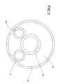
- Figure 5 shows a schematic and partial view of a detail of Figure 2, obtained by sectioning Figure 2 itself with a plane V-V;
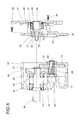
- Figure 6 shows a sectioned and partially exploded view of a reducer with two gear pairs realised in accordance with the present invention;
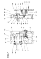
- Figure 7 shows a sectioned and partially exploded view of a reducer with three gear pairs realised in accordance with the present invention.
- In Figure 1, the
number 1 indicates in its entirety a first type of reducer device known in the art, which comprises abox body 2 constituted by acasing 3, by anadditional casing sector 4 and by acover 5 mutually connected in pairs and in the order described above with interposition of sealing elements for the lubricating fluids not shown. - In the description that follows reference shall be made to a plurality of axes constituting respective geometric entities of reference of respective mechanical details; such axes are all mutually parallel, and they are parallel to the directions of longitudinal development of the reducers which shall be described.
- The
casing 3 is provided with ahole 6 with horizontal axis, obtained in one of itswalls 7 positioned to the left in Figure 1 and housing within it twoball bearings 8 supporting with their inner rings anoutput shaft 9 with horizontal axis of thereducer 1, provided with an end portion projecting from thebox body 2. On the other end of theshaft 9 is coaxially splined agear wheel 10, which is engaged with agear wheel 11 splined (or obtained from the same piece) in correspondence with an intermediate portion of atree 12 with horizontal axis. The end of theshaft 12 positioned to the left in Figure 1 is housed inside the inner ring of a ball bearing 13 presenting its own outer ring fitted within ahole 14 obtained in an internal position of thecasing 3 located below thehole 6, while, to the side of thegear wheel 11, on theshaft 12 is coaxially splined afurther gear wheel 15. The right-side end of theshaft 12 is housed inside the inner ring of abearing 16, whose outer ring is fitted within ahole 17 with which the aforesaidadditional casing sector 4 is provided. Suchadditional casing sector 4 is further provided, above thehole 17, with ahole 18 with horizontal axis within which is fitted the inner ring of a ball bearing 19 supporting coaxially with its inner ring a median portion of ashaft 20. On an end portion ofsuch shaft 20 positioned to the left in Figure 1 is splined (or obtained from the same piece) agear wheel 21 able to engage, in use, with theaforementioned gear wheel 15, whilst immediately to the right of thebearing 19 theshaft 20 bears splined anadditional gear wheel 22. The right end portion of theshaft 20 is housed within the inner ring of a ball bearing 23, whose outer ring can be housed inside acavity 24 present in theaforementioned cover 5. - Inside a
hole 25 of thecover 5, positioned below thecavity 24, are housed the outer rings of twoball bearings shaft 28 with horizontal axis. - On the end of
shaft 28 positioned to the left in Figure 1 is splined (or obtained from one piece) agear wheel 29, able to co-operate, in use, with theaforementioned gear wheel 22. - The right end of the
shaft 28 is provided coaxially with acavity 30 able to be engaged by the output shaft (not shown) of a motor that is not shown, which is connectable to aflange 31 comprised in thecover 5 by means of connecting elements constituted, for instance, by screws (not shown). - The
reducer 1 just described is provided with three pairs ofgear wheels - As briefly mentioned, if in the
reducer 1 in question only two pairs of gear wheels are to be used, it is necessary to replace both theadditional casing sector 4, and thecover 5. - Figures 2 and 3 show a
reducer 32 of the second type described in the premises to the present description. -
Such reducer 32, of the type with two gear pairs, comprises abox body 33 constituted by acasing 34, in turn constituted by a substantiallycylindrical element 35 closed, in correspondence with its end positioned to the left in Figures 2 and 3, by acover 36, and, in correspondence with its end positioned to the right, by acover 37. The axial ends of theelement 35 and therespective covers - The
cover 36 is provided with ahole 38 with horizontal axis, housing within it a ball bearing 39 supporting with its inner ring anoutput shaft 40 of thereducer 32 with horizontal axis, provided with an end portion projecting from thebox body 33. On the other end of theshaft 40 is coaxially splined agear wheel 41, which is engaged with agear wheel 42 splined (or obtained from the same piece) in correspondence with an intermediate portion of ashaft 43 with horizontal axis. - As shown in Figures 2 and 3, the end of the
shaft 43, positioned to the left in Figures 2 and 3, is housed within the inner ring of a ball bearing 44 presenting its own outer ring fitted within ahole 45 obtained in an inner portion of thecasing 34 located below thehole 38. - As shown in Figure 2, in proximity with the right side of the
gear wheel 42, on theshaft 43 is fitted the inner ring of a ball bearing 46 whose outer ring is housed within ahole 47 obtained in awall 48 which, perpendicularly to the axis of theshaft 40, transversely delimits an intermediate inner area of thecasing 34. - In
such wall 48, above thehole 47, is present ahole 49 housing the outer ring of a ball bearing 50, whose inner ring is fitted coaxially to a right end portion of theaforementioned shaft 40. - On the right end portion of the
shaft 43 is splined coaxially agear wheel 51, which is engaged with afurther gear wheel 52 splined on a left end portion of ashaft 53, which is supported in a rotating manner by means of twoball bearings 54 housed within ahole 55 obtained in theaforesaid cover 37. - The right end of the
shaft 53 is coaxially provided with acavity 56 able to be engaged by the output shaft of a motor not shown herein, which is connectable to aflange 57 comprised in thecover 37 by means of connecting elements constituted, for instance, by screws (not shown). - The
reducer 32 just described is provided with two reduction stages constituted by two pairs ofgear wheels - As mentioned, to the
casing 34 of thereducer 32 is stably associated theaforesaid wall 48, better shown in the schematic Figure 7, wherein are always present, although used only in part as in the case just described, theaforementioned holes additional ground hole 58; thehole 58 is able to house possible means for supporting a third gear pair, and, as specified above, its presence, in the case of use of only two gear pairs, entails needlessly high costs to manufacture thecasing 34 and, as a result, theentire reducer 32. - Similarly to what is shown in Figure 2, as shown in Figure 3, in proximity to the right side of the
gear wheel 42, theshaft 43 passes through a ground hole, not shown in Figure 3 and obtained in awall 48 which, perpendicularly to the axis of theshaft 40, transversely delimits an inner intermediate area of thecasing 34. The hole through which theshaft 43 passes corresponds to thehole 58 of Figure 5 and itswall 48 corresponds to thewall 48 of Figure 2. - To the right of the
wall 48 of Figure 3, on theshaft 43 is fitted the inner ring of a ball bearing 46 whose outer ring is housed within ahole 47 obtained in awall 110 with which thecasing 34 is provided. To the right end of theshaft 43 of Figure 3 is splined agear wheel 51 which engages afurther gear wheel 52 splined on a left end portion of ashaft 53, which is supported rotatorily by means of a ball bearing 54 housed inside ahole 55 obtained in theaforesaid cover 37. - In the case shown in Figure 3 the
shaft 53 can coincide with the output shaft of a motor not shown, which is connectable to theflange 57 comprised in thecover 37 by means of connecting elements known in the art and not shown. - Similarly to the
reducer 32 shown in Figure 2, also thereducer 32 described above with reference to Figure 3 is provided with two reduction stages constituted by two pairs ofgear wheels - Figure 4 shows the same reducer as in Figure 3, but provided with three reduction stages. In particular the
wall 48 is sectioned according to two different planes whereof one coincides with the section plane of Figure 3 and the other one is offset with respect to the axis of theshaft 40 towards an observer looking at Figure 4. This second section plane highlights that thewall 48 is provided, in addition to theaforementioned hole 49, with afurther hole 111 which supports, by means of abearing 112, the right end of anadditional shaft 113. Theshaft 113 is provided, to the right of thehole 111, with awheel 114 which enmeshes with asecond wheel 115 obtained on theshaft 43. - As shown in Figure 4, the
shaft 113 is driven byshaft 43 through the reduction pair constituted by thewheel 115 and by thewheel 114, and it is provided with awheel 116 that enmeshes with thewheel 41. In particular thewheel 116 and thewheel 41 constitute an additional reduction stage. The reducer shown in Figure 4 is thus provided with three reduction stages, constituted by the three pairs of gear wheels indicated, respectively with thenumbers - Also in the case shown in Figure 4, to the
casing 34 of thereducer 32 is stably associated theaforementioned wall 48, which in the case shown in Figure 3 is identical to the one shown in Figure 4, and in the case of Figure 3 relating to a reducer with two reduction stages, inwall 48 are still present, although used only partially as in the case just described, theaforementioned holes further hole 111 shown only in Figure 4. - Also in this additional case shown in Figures 3 and 4, the
hole 111 is present both for the reducer with two reduction stages, and for the reducer with three reduction stages. - Figured 6 and 7 respectively show two
reducers 59 and 59' realised in accordance with the present invention, provided respectively with two and with three gear pairs. - Both
reducers 59 and 59' comprise abox body 59" defined by acasing 60 having the shape of a cup body with the bottom located to the left in the figures in question, and which is always the same for any type of reducer, both in the case wherein the reducer presents two reduction stages, and in the case wherein the reducer presents three reduction stages. The inlet ofsuch casing 60, positioned to the right in Figures 6 and 7, is closed by a cover comprised in thebox body 59" and indicated respectively, in Figures 6 and 7, with thenumbers casing 60 is provided with ahole 63 with horizontal axis, obtained in itswall 64 located to the left in Figures 6 and 7 and housing within it twoball bearings 65 supporting with their inner rings anoutput shaft 66 of thereducer 59, with horizontal axis, provided with an end portion projecting from thecasing 60. On the other end of theshaft 66 is coaxially splined agear wheel 67, which is engaged with agear wheel 68 splined (or obtained from one piece) in correspondence with an intermediate portion of ashaft 69 with horizontal axis. The end of theshaft 69 positioned to the left in Figures 6 and 7 is housed inside the inner ring of aball bearing 70 presenting its own outer ring fit inside ahole 71 obtained in an inner portion of thecasing 60 positioned below thehole 63, whilst, to the side of thegear wheel 68, on theshaft 69 is coaxially splined afurther gear wheel 72. The right end of theshaft 69 is housed inside the inner ring of abearing 73, whose outer ring is fitted within ahole 74 obtained in awall covers - As shown in Figure 6, in a portion of the
wall 75 overlying thehole 74 is obtained afurther hole 77 with horizontal axis, within which is coaxially housed the outer ring of aball bearing 78 whose function shall become readily apparent hereafter. An end ofsuch hole 77 positioned to the right in Figure 3 communicates with aninner cavity 79 of asleeve 80 coaxial to thehole 77 itself and presenting its left end integral with thewall 75. Within thesleeve 80 is coaxially housed aball bearing 81, which, in combination with theaforementioned bearing 78, supports in a rotatory manner ashaft 82 on whose end portions positioned within thecasing 60 and extending leftwards in Figure 6 is splined (or obtained from the same piece) agear wheel 83 able to co-operate with theaforementioned gear wheel 72. - The right end of the
shaft 82 is provided coaxially with acavity 84 able to be engaged by the output shaft of a motor not shown herein, which is connectable to aflange 85, comprised in thecover 61 and connected to the right end of thesleeve 80, through connecting elements constituted, for instance, by screws 86. - As shown in Figure 7, the
aforementioned wall 76 partially delimits the left flank of thecover 62 oriented towards thecasing 60, and it is provided, in correspondence with its portion overlying thehole 74, with anadditional hole 87 with horizontal axis, within which is coaxially housed the outer ring of aball bearing 88 whose function shall become readily apparent hereafter. One end ofsuch hole 87 positioned to the right in Figure 7 communicates with acavity 89 included between thewall 76 and awall 90 defining the base, situated to the right of thewall 76 in Figure 7, of acup body 91 constituting substantially the body of thecover 62. - An upper portion of the
wall 90 is provided with ablind hole 92 coaxial to theaforementioned hole 87, within which is housed the outer ring of aball bearing 93 which, in combination with theaforementioned bearing 88, supports in a rotatory manner ashaft 94 on whose median portion is splined agear wheel 95. On the end portion of theshaft 94 positioned internally to thecasing 60 and extending leftwards in Figure 7 is splined (or obtained from the same piece) agear wheel 96 able to co-operate with theaforementioned gear wheel 72. - To the surface of the
wall 90 positioned to the right, in Figure 7, and oriented towards the exterior of thecover 62 is connected asleeve 97 developing along a horizontal axis and presenting its own left end integral with thewall 90 itself. Thesleeve 97 is provided internally with acavity 98 coaxial thereto, whose left end is coaxially adjacent to ahole 99 obtained in thewall 90. Withinsuch hole 99 is coaxially housed aball bearing 100, which co-operates with aball bearing 101 housed coaxially within thesleeve 97 to support in a rotatory manner ashaft 102 with horizontal axis, on whose end portion positioned internally to thecasing 60 and extending leftwards in Figure 7 is splined (or obtained from the same piece) agear wheel 103 able to co-operate with theaforementioned gear wheel 95. - The right end of the
shaft 102 is provided coaxially with acavity 104 able to be engaged by the output shaft of a motor not shown herein, which is connectable to aflange 105, comprised in thecover 62 and connected to the right end of thesleeve 97 through connecting elements constituted, for instance, byscrews 106. Theflanges covers reducer 59 of Figure 3 or to the reducer 59' of Figure 7. - In particular, the
flanges wall 76 is present, as in the reducer 59' of Figure 7, the motor (not shown) able to be associated to the reducer 59' shall preferably be less powerful, and hence smaller, for the same value of torque output byshaft 66, than the motor associated to thereducer 59. - The
reducers 59 and 59' represented in Figures 6 and 7 operate in a way known in itself, the motion being imparted to thereducers 59 and 59' themselves through therespective input shafts respective output shafts 66. - For the realisation of the
reducers 59 and 59', as stated, thesame casing 60 is used, with all the components contained therein, whilst it is sufficient to associate to thecasing 60, respectively, thecover 61 or 62 (with the elements associated thereto) to obtain thereducer 59 with two gear pairs or the reducer 59' with three gear pairs. From the above description it is evident that thereducers 59 and 59' fully attain the intended aim, since for their realisation, in addition to thecasing 60 and to the related internal components, common to both, it is sufficient to realise and keep in stock only the different types of covers (and the components associated thereto) able to meet the various requirements. - Note that, thanks to their conformation, the
reducers 59 and 59' described above present greater rigidity than the reducers realised in accordance with the prior art, and the complexes constituted by thecasing 60 and by thecovers - The invention thus conceived can be subject to numerous modifications and variations without thereby departing from the scope of the inventive concept. For instance, the
wall 76 may not constitute a part of thecover 62, and it may be connected tosuch cover 62 through connecting elements constituted, for instance, by screws. - Lastly, it should be noted that all components described could be replaced with technically equivalent elements.
Claims (11)
- Speed varying device, characterised in that it comprises a box body (59") for housing and supporting a set number of gear pairs (67, 68, 72, 83, 95, 96, 103) variable according to the speed variation ratio of the device (59, 59') itself, said gear pairs (67, 68, 72, 83, 95, 96, 103) being kinematically connected to each other to transmit the motion between an input shaft (82; 102) and an output shaft (66) of said varying device (59; 59'); said box body (59") being defined by a casing (60) which is always the same for any set number of said gear pairs (67, 68, 72, 83, 95, 96, 103), and presenting substantially the shape of a cup body and supporting a set number of said gears (67, 68, 72) kinematically connected to each other; to said casing (60) being connectable one of at least two covers (61; 62) chosen according to the determined number of gear pairs (67, 68, 72, 83, 95, 96, 103) present in the speed varying device (59, 59'); each of said two covers (61, 62) supporting an additional set number of said gears (83 or 95, 96, 103) complementary to said set number of said gears (67, 68, 72) present in said casing to form said required variation ratio of said device (59, 59'), and to at least one of said two covers (61, 62) being associated, internally to said box body (59"), a wall (76) for supporting a part (95, 96) of said additional set number of gears (95, 96, 103), which is present only in the case of a set number of said gear pairs (67, 68, 72, 83, 95, 96, 103) and according to respective different embodiments of said speed varying device (59; 59').
- Device according to claim 1, characterised in that, in the case wherein said box (59") houses within it two gear pairs (67, 68, 72, 83), said device (59) comprises a cover (61), selected from the at least two covers (61, 62) provided, which lacks said wall (76).
- Device according to claim 1, characterised in that, in the case wherein said box body (59") houses within it three said gear pairs (67, 68, 72, 95, 96, 103), said device (59') comprises a cover (62), selected from the at least two covers (61, 62) provided, which has said wall (76).
- Device according to claim 2, characterised in that said casing (60) supports and houses within it a first gear pair (67, 68) connected to said output shaft (66), and a first gear (72) coaxially integral to a gear (68) of said first pair; said cover (61) supporting a second gear (83) in engagement with said first gear (72) and connected to said input shaft (82); and said first and second gears (72, 83) constituting a second gear pair.
- Device according to claim 3, characterised in that said casing (60) supports and houses within it a first gear pair (67, 68) connected to said output shaft (66), and a first gear (72) coaxially integral with a gear (68) of said first pair; said cover (62) supporting, with the aid of said wall (76), a second gear pair (95, 103) connected to said input shaft (102), and a second gear (96) coaxially integral to a gear (95) of said second pair; and said first and second gears (72, 96) constituting a third gear pair.
- Device according to any one of the claims from 1 to 5, characterised in that said wall (76) constitutes a part of said cover (62).
- Device according to any one of the claims from 1 to 5, characterised in that said wall (76) is connected in a removable manner to said cover (62).
- Device according to claim 6 or 7, characterised in that said wall (76) is positioned perpendicular to a direction of longitudinal development of said speed varying device (59').
- Device according to any one of the claims from 6 to 8, characterised in that said wall (76) is positioned perpendicular to the axes of rotation of said gears (67, 68, 72, 95, 96, 103).
- Device according to any one of the claims from 1 to 9, characterised in that to said cover (61; 62) is associated a flange (85; 105) able to be connected to a motor for actuating said speed varying device (59; 59'); said flange (85; 105) presenting different dimensions and/or conformation depending on whether said wall (76) is present or not.
- Device according to any of the claims from 1 to 10, characterised in that said speed varying device (59; 59') is a speed reducer.
Applications Claiming Priority (2)
| Application Number | Priority Date | Filing Date | Title |
|---|---|---|---|
| ITBO980454 | 1998-07-21 | ||
| IT1998BO000454A IT1306265B1 (en) | 1998-07-21 | 1998-07-21 | SPEED VARIATOR DEVICE |
Publications (2)
| Publication Number | Publication Date |
|---|---|
| EP0974774A1 true EP0974774A1 (en) | 2000-01-26 |
| EP0974774B1 EP0974774B1 (en) | 2003-10-15 |
Family
ID=11343326
Family Applications (1)
| Application Number | Title | Priority Date | Filing Date |
|---|---|---|---|
| EP99830460A Expired - Lifetime EP0974774B1 (en) | 1998-07-21 | 1999-07-19 | Speed reducing device |
Country Status (6)
| Country | Link |
|---|---|
| US (1) | US6263760B1 (en) |
| EP (1) | EP0974774B1 (en) |
| AT (1) | ATE252206T1 (en) |
| DE (1) | DE69912038T2 (en) |
| ES (1) | ES2209374T3 (en) |
| IT (1) | IT1306265B1 (en) |
Cited By (4)
| Publication number | Priority date | Publication date | Assignee | Title |
|---|---|---|---|---|
| US6581496B2 (en) | 2000-07-06 | 2003-06-24 | Hans Heidolph Gmbh & Co. Kg | Small size transmission |
| WO2011006600A1 (en) | 2009-07-14 | 2011-01-20 | Sew-Eurodrive Gmbh & Co. Kg | Gear motor, and production method for a gear motor |
| ITVI20090295A1 (en) * | 2009-12-16 | 2011-06-17 | Hydro Mec S R L | GEAR REDUCER CONTAINER |
| WO2024217751A1 (en) * | 2023-04-20 | 2024-10-24 | Knorr-Bremse Systeme für Nutzfahrzeuge GmbH | Method for producing a transmission, and a transmission |
Families Citing this family (2)
| Publication number | Priority date | Publication date | Assignee | Title |
|---|---|---|---|---|
| DE102005008711A1 (en) * | 2005-02-25 | 2006-09-14 | Zf Friedrichshafen Ag | Ball bearing securing device, has omega circlip which is mounted before assembly of bearing cover such that borehole lockable by screw cap for mounting axial safety device is omitted |
| SE535444C2 (en) * | 2010-10-13 | 2012-08-14 | Autoinvent Transip Ab | Stationary gear unit |
Citations (2)
| Publication number | Priority date | Publication date | Assignee | Title |
|---|---|---|---|---|
| EP0387367A1 (en) * | 1989-03-06 | 1990-09-19 | Francisco Fenollar Manrique | Speed reducer |
| EP0507309A1 (en) * | 1991-04-04 | 1992-10-07 | Sumitomo Heavy Industries, Ltd. | Motor-equipped reduction gear device with a pre-stage |
Family Cites Families (5)
| Publication number | Priority date | Publication date | Assignee | Title |
|---|---|---|---|---|
| BE747171A (en) * | 1970-03-11 | 1970-09-11 | Machinery And Gears Hansen N V | RANGE OF GEAR REDUCTION GEARBOXES, |
| US3771381A (en) * | 1972-06-30 | 1973-11-13 | Honeywell Inc | Miniature electric trend recorder high torque speed reducer |
| US4431073A (en) * | 1981-12-03 | 1984-02-14 | Fairfield Manufacturing Co., Inc. | Two speed final drive gear box |
| US5095767A (en) * | 1990-08-23 | 1992-03-17 | Geartechnic Corporation | Multi-configuration gear reducer kit |
| US6029532A (en) * | 1997-01-31 | 2000-02-29 | Reliance Electric Industrial Company | Gearing commonality system for gear reducers |
-
1998
- 1998-07-21 IT IT1998BO000454A patent/IT1306265B1/en active
-
1999
- 1999-07-16 US US09/356,258 patent/US6263760B1/en not_active Expired - Lifetime
- 1999-07-19 ES ES99830460T patent/ES2209374T3/en not_active Expired - Lifetime
- 1999-07-19 AT AT99830460T patent/ATE252206T1/en not_active IP Right Cessation
- 1999-07-19 EP EP99830460A patent/EP0974774B1/en not_active Expired - Lifetime
- 1999-07-19 DE DE69912038T patent/DE69912038T2/en not_active Expired - Lifetime
Patent Citations (2)
| Publication number | Priority date | Publication date | Assignee | Title |
|---|---|---|---|---|
| EP0387367A1 (en) * | 1989-03-06 | 1990-09-19 | Francisco Fenollar Manrique | Speed reducer |
| EP0507309A1 (en) * | 1991-04-04 | 1992-10-07 | Sumitomo Heavy Industries, Ltd. | Motor-equipped reduction gear device with a pre-stage |
Cited By (4)
| Publication number | Priority date | Publication date | Assignee | Title |
|---|---|---|---|---|
| US6581496B2 (en) | 2000-07-06 | 2003-06-24 | Hans Heidolph Gmbh & Co. Kg | Small size transmission |
| WO2011006600A1 (en) | 2009-07-14 | 2011-01-20 | Sew-Eurodrive Gmbh & Co. Kg | Gear motor, and production method for a gear motor |
| ITVI20090295A1 (en) * | 2009-12-16 | 2011-06-17 | Hydro Mec S R L | GEAR REDUCER CONTAINER |
| WO2024217751A1 (en) * | 2023-04-20 | 2024-10-24 | Knorr-Bremse Systeme für Nutzfahrzeuge GmbH | Method for producing a transmission, and a transmission |
Also Published As
| Publication number | Publication date |
|---|---|
| DE69912038T2 (en) | 2004-10-07 |
| ES2209374T3 (en) | 2004-06-16 |
| IT1306265B1 (en) | 2001-06-04 |
| US6263760B1 (en) | 2001-07-24 |
| ATE252206T1 (en) | 2003-11-15 |
| ITBO980454A1 (en) | 2000-01-21 |
| DE69912038D1 (en) | 2003-11-20 |
| EP0974774B1 (en) | 2003-10-15 |
Similar Documents
| Publication | Publication Date | Title |
|---|---|---|
| JP6596364B2 (en) | Motor type power unit | |
| CN111120583A (en) | Speed reduction device and electromechanical device | |
| US12181021B2 (en) | Transmission housing, gearbox and wheeled vehicle provided with such a gearbox | |
| EP0507309B1 (en) | Motor-equipped reduction gear device with a pre-stage | |
| EP0974774A1 (en) | Speed reducing device | |
| JP3984010B2 (en) | Engine balancer equipment | |
| US2480210A (en) | Multiratio drive mechanism, especially for the axles of motor vehicles | |
| JP2016141198A (en) | Vehicle drive device | |
| US3779675A (en) | Drive system for a plurality of worm driven compressors | |
| JPH07298547A (en) | Coupling structure for transmission and motor | |
| KR100642307B1 (en) | Hollow motor reducer | |
| EP1039171A2 (en) | Gearbox, in particular for motorcycles | |
| CA1160475A (en) | Speed change mechanism | |
| WO2020026042A2 (en) | Kit for a gearbox, gearbox device comprising the kit and method for manufacturing a gearbox device | |
| ITBO990052U1 (en) | GEARMOTOR INCLUDING AN ENDLESS SCREW REDUCER - WHEEL WHEEL. | |
| RU197171U1 (en) | DISTRIBUTION BOX | |
| JPH0741965Y2 (en) | Transfer device | |
| JP4303434B2 (en) | Series of hypoid reducers and hypoid reducers | |
| JP2018146020A (en) | Differential device | |
| JPH0444919Y2 (en) | ||
| US7861616B2 (en) | Vehicle transmission | |
| WO2018100988A1 (en) | Transmission device for vehicle | |
| JPH0741966Y2 (en) | Transfer device | |
| JP3065770B2 (en) | Vehicle powertrain structure | |
| RU2276640C1 (en) | Vehicle gearbox |
Legal Events
| Date | Code | Title | Description |
|---|---|---|---|
| PUAI | Public reference made under article 153(3) epc to a published international application that has entered the european phase |
Free format text: ORIGINAL CODE: 0009012 |
|
| AK | Designated contracting states |
Kind code of ref document: A1 Designated state(s): AT BE CH CY DE DK ES FI FR GB GR IE IT LI LU MC NL PT SE |
|
| AX | Request for extension of the european patent |
Free format text: AL;LT;LV;MK;RO;SI |
|
| 17P | Request for examination filed |
Effective date: 20000620 |
|
| AKX | Designation fees paid |
Free format text: AT BE CH CY DE DK ES FI FR GB GR IE IT LI LU MC NL PT SE |
|
| 17Q | First examination report despatched |
Effective date: 20011227 |
|
| GRAH | Despatch of communication of intention to grant a patent |
Free format text: ORIGINAL CODE: EPIDOS IGRA |
|
| GRAS | Grant fee paid |
Free format text: ORIGINAL CODE: EPIDOSNIGR3 |
|
| GRAA | (expected) grant |
Free format text: ORIGINAL CODE: 0009210 |
|
| RAP1 | Party data changed (applicant data changed or rights of an application transferred) |
Owner name: VARVEL S.P.A. |
|
| AK | Designated contracting states |
Kind code of ref document: B1 Designated state(s): AT BE CH CY DE DK ES FI FR GB GR IE IT LI LU MC NL PT SE |
|
| PG25 | Lapsed in a contracting state [announced via postgrant information from national office to epo] |
Ref country code: NL Free format text: LAPSE BECAUSE OF FAILURE TO SUBMIT A TRANSLATION OF THE DESCRIPTION OR TO PAY THE FEE WITHIN THE PRESCRIBED TIME-LIMIT Effective date: 20031015 Ref country code: LI Free format text: LAPSE BECAUSE OF FAILURE TO SUBMIT A TRANSLATION OF THE DESCRIPTION OR TO PAY THE FEE WITHIN THE PRESCRIBED TIME-LIMIT Effective date: 20031015 Ref country code: FI Free format text: LAPSE BECAUSE OF FAILURE TO SUBMIT A TRANSLATION OF THE DESCRIPTION OR TO PAY THE FEE WITHIN THE PRESCRIBED TIME-LIMIT Effective date: 20031015 Ref country code: CY Free format text: LAPSE BECAUSE OF FAILURE TO SUBMIT A TRANSLATION OF THE DESCRIPTION OR TO PAY THE FEE WITHIN THE PRESCRIBED TIME-LIMIT Effective date: 20031015 Ref country code: CH Free format text: LAPSE BECAUSE OF FAILURE TO SUBMIT A TRANSLATION OF THE DESCRIPTION OR TO PAY THE FEE WITHIN THE PRESCRIBED TIME-LIMIT Effective date: 20031015 Ref country code: BE Free format text: LAPSE BECAUSE OF FAILURE TO SUBMIT A TRANSLATION OF THE DESCRIPTION OR TO PAY THE FEE WITHIN THE PRESCRIBED TIME-LIMIT Effective date: 20031015 Ref country code: AT Free format text: LAPSE BECAUSE OF FAILURE TO SUBMIT A TRANSLATION OF THE DESCRIPTION OR TO PAY THE FEE WITHIN THE PRESCRIBED TIME-LIMIT Effective date: 20031015 |
|
| REG | Reference to a national code |
Ref country code: GB Ref legal event code: FG4D Ref country code: CH Ref legal event code: EP |
|
| REG | Reference to a national code |
Ref country code: IE Ref legal event code: FG4D |
|
| REF | Corresponds to: |
Ref document number: 69912038 Country of ref document: DE Date of ref document: 20031120 Kind code of ref document: P |
|
| PG25 | Lapsed in a contracting state [announced via postgrant information from national office to epo] |
Ref country code: SE Free format text: LAPSE BECAUSE OF FAILURE TO SUBMIT A TRANSLATION OF THE DESCRIPTION OR TO PAY THE FEE WITHIN THE PRESCRIBED TIME-LIMIT Effective date: 20040115 Ref country code: GR Free format text: LAPSE BECAUSE OF FAILURE TO SUBMIT A TRANSLATION OF THE DESCRIPTION OR TO PAY THE FEE WITHIN THE PRESCRIBED TIME-LIMIT Effective date: 20040115 Ref country code: DK Free format text: LAPSE BECAUSE OF FAILURE TO SUBMIT A TRANSLATION OF THE DESCRIPTION OR TO PAY THE FEE WITHIN THE PRESCRIBED TIME-LIMIT Effective date: 20040115 |
|
| NLV1 | Nl: lapsed or annulled due to failure to fulfill the requirements of art. 29p and 29m of the patents act | ||
| REG | Reference to a national code |
Ref country code: CH Ref legal event code: PL |
|
| REG | Reference to a national code |
Ref country code: ES Ref legal event code: FG2A Ref document number: 2209374 Country of ref document: ES Kind code of ref document: T3 |
|
| ET | Fr: translation filed | ||
| PG25 | Lapsed in a contracting state [announced via postgrant information from national office to epo] |
Ref country code: LU Free format text: LAPSE BECAUSE OF NON-PAYMENT OF DUE FEES Effective date: 20040719 Ref country code: IE Free format text: LAPSE BECAUSE OF NON-PAYMENT OF DUE FEES Effective date: 20040719 |
|
| PG25 | Lapsed in a contracting state [announced via postgrant information from national office to epo] |
Ref country code: MC Free format text: LAPSE BECAUSE OF NON-PAYMENT OF DUE FEES Effective date: 20040731 |
|
| PLBE | No opposition filed within time limit |
Free format text: ORIGINAL CODE: 0009261 |
|
| STAA | Information on the status of an ep patent application or granted ep patent |
Free format text: STATUS: NO OPPOSITION FILED WITHIN TIME LIMIT |
|
| 26N | No opposition filed |
Effective date: 20040716 |
|
| REG | Reference to a national code |
Ref country code: IE Ref legal event code: MM4A |
|
| PG25 | Lapsed in a contracting state [announced via postgrant information from national office to epo] |
Ref country code: PT Free format text: LAPSE BECAUSE OF NON-PAYMENT OF DUE FEES Effective date: 20040315 |
|
| REG | Reference to a national code |
Ref country code: FR Ref legal event code: PLFP Year of fee payment: 18 |
|
| REG | Reference to a national code |
Ref country code: FR Ref legal event code: PLFP Year of fee payment: 19 |
|
| PGFP | Annual fee paid to national office [announced via postgrant information from national office to epo] |
Ref country code: FR Payment date: 20170727 Year of fee payment: 19 Ref country code: ES Payment date: 20170830 Year of fee payment: 19 Ref country code: GB Payment date: 20170728 Year of fee payment: 19 Ref country code: IT Payment date: 20170726 Year of fee payment: 19 |
|
| PGFP | Annual fee paid to national office [announced via postgrant information from national office to epo] |
Ref country code: DE Payment date: 20170929 Year of fee payment: 19 |
|
| REG | Reference to a national code |
Ref country code: DE Ref legal event code: R119 Ref document number: 69912038 Country of ref document: DE |
|
| GBPC | Gb: european patent ceased through non-payment of renewal fee |
Effective date: 20180719 |
|
| PG25 | Lapsed in a contracting state [announced via postgrant information from national office to epo] |
Ref country code: GB Free format text: LAPSE BECAUSE OF NON-PAYMENT OF DUE FEES Effective date: 20180719 Ref country code: DE Free format text: LAPSE BECAUSE OF NON-PAYMENT OF DUE FEES Effective date: 20190201 Ref country code: FR Free format text: LAPSE BECAUSE OF NON-PAYMENT OF DUE FEES Effective date: 20180731 |
|
| PG25 | Lapsed in a contracting state [announced via postgrant information from national office to epo] |
Ref country code: IT Free format text: LAPSE BECAUSE OF NON-PAYMENT OF DUE FEES Effective date: 20180719 |
|
| REG | Reference to a national code |
Ref country code: ES Ref legal event code: FD2A Effective date: 20190917 |
|
| PG25 | Lapsed in a contracting state [announced via postgrant information from national office to epo] |
Ref country code: ES Free format text: LAPSE BECAUSE OF NON-PAYMENT OF DUE FEES Effective date: 20180720 |