EP0976650A2 - Structure en composite pour aéronef et procédé pour sa fabrication - Google Patents
Structure en composite pour aéronef et procédé pour sa fabrication Download PDFInfo
- Publication number
- EP0976650A2 EP0976650A2 EP99115003A EP99115003A EP0976650A2 EP 0976650 A2 EP0976650 A2 EP 0976650A2 EP 99115003 A EP99115003 A EP 99115003A EP 99115003 A EP99115003 A EP 99115003A EP 0976650 A2 EP0976650 A2 EP 0976650A2
- Authority
- EP
- European Patent Office
- Prior art keywords
- composite material
- skin
- airfoil
- spar
- ribs
- Prior art date
- Legal status (The legal status is an assumption and is not a legal conclusion. Google has not performed a legal analysis and makes no representation as to the accuracy of the status listed.)
- Withdrawn
Links
- 239000002131 composite material Substances 0.000 title claims abstract description 94
- 238000000034 method Methods 0.000 title claims description 47
- 238000004519 manufacturing process Methods 0.000 title description 9
- 239000000853 adhesive Substances 0.000 claims abstract description 31
- 230000001070 adhesive effect Effects 0.000 claims abstract description 31
- 239000006260 foam Substances 0.000 claims description 41
- 238000010030 laminating Methods 0.000 claims description 30
- 239000003292 glue Substances 0.000 claims description 27
- 229920001187 thermosetting polymer Polymers 0.000 claims description 26
- 238000000465 moulding Methods 0.000 claims description 10
- 230000013011 mating Effects 0.000 claims description 8
- 235000011837 pasties Nutrition 0.000 claims description 5
- 238000004026 adhesive bonding Methods 0.000 claims description 3
- 238000000151 deposition Methods 0.000 claims 1
- 239000000470 constituent Substances 0.000 abstract description 12
- 239000011162 core material Substances 0.000 description 42
- 238000010586 diagram Methods 0.000 description 25
- 239000004918 carbon fiber reinforced polymer Substances 0.000 description 6
- 238000010276 construction Methods 0.000 description 6
- 210000000569 greater omentum Anatomy 0.000 description 4
- 230000000630 rising effect Effects 0.000 description 4
- 229910000831 Steel Inorganic materials 0.000 description 2
- 239000010959 steel Substances 0.000 description 2
- XAGFODPZIPBFFR-UHFFFAOYSA-N aluminium Chemical compound [Al] XAGFODPZIPBFFR-UHFFFAOYSA-N 0.000 description 1
- 229910052782 aluminium Inorganic materials 0.000 description 1
- 230000000694 effects Effects 0.000 description 1
- 239000004744 fabric Substances 0.000 description 1
- 238000010438 heat treatment Methods 0.000 description 1
- 150000003949 imides Chemical class 0.000 description 1
- 238000003754 machining Methods 0.000 description 1
- 238000012986 modification Methods 0.000 description 1
- 230000004048 modification Effects 0.000 description 1
- 238000011417 postcuring Methods 0.000 description 1
- 238000007789 sealing Methods 0.000 description 1
- 239000003566 sealing material Substances 0.000 description 1
- 238000007493 shaping process Methods 0.000 description 1
- 239000003381 stabilizer Substances 0.000 description 1
Images


Classifications
-
- B—PERFORMING OPERATIONS; TRANSPORTING
- B64—AIRCRAFT; AVIATION; COSMONAUTICS
- B64C—AEROPLANES; HELICOPTERS
- B64C3/00—Wings
- B64C3/18—Spars; Ribs; Stringers
-
- B—PERFORMING OPERATIONS; TRANSPORTING
- B64—AIRCRAFT; AVIATION; COSMONAUTICS
- B64C—AEROPLANES; HELICOPTERS
- B64C3/00—Wings
- B64C3/20—Integral or sandwich constructions
-
- B—PERFORMING OPERATIONS; TRANSPORTING
- B64—AIRCRAFT; AVIATION; COSMONAUTICS
- B64C—AEROPLANES; HELICOPTERS
- B64C3/00—Wings
- B64C3/26—Construction, shape, or attachment of separate skins, e.g. panels
Definitions
- the present invention pertains to airfoil structures of composite material used in part of an aircraft elevator or wing, for example, as well as to methods of forming such airfoil structures. More particularly, the invention relates to airfoil structures of composite material which are easy to manufacture and provide a high peeling strength as well as to their forming methods.
- FIGS. 19 to 21 show an elevator surface structure of a related art aircraft using composite materials, in which the aircraft's elevator 1 is constructed by individually forming an upper skin 2, a lower skin 3, a spar 4 and ribs 5 using the composite materials and, then, assembling them by use of fastener means 6, such as bolts and nuts.
- the related art aircraft elevator 1 has such problems that it involves a large number of principal constituent components, requiring high manufacturing costs for those components, and because they need to be assembled by using a number of fasteners, assembling component costs are also high.
- a further problem is that it is necessary to make many holes for fitting the fasteners, resulting in an increase in man-hours required for assembly work.
- Box-structure airfoils in which a frame is produced by previously fastening spars and ribs with clips to reduce the man-hours required for assembly with fasteners and upper and lower skins are bonded to the frame are disclosed in European Patent Bulletin Publication No. 485027 and published U.S. Patent No. 5216799, for example.
- structures shown in FIGS. 22 and 23 in which a frame 7 and a skin 8 are bonded by using an adhesive 9 have a low out-of-plane peeling load (peeling load exerted in a direction perpendicular to the skin 8) compared to fastener assembly, and this would pose a problem related to strength.
- the frame 7 of the I-shaped cross section entails approximately twice as high manufacturing cost as the frame 7 of the U-shaped cross section, thus developing a problem of increased cost.
- the invention has been made in consideration of these situations. Accordingly, it is an object of the invention to provide airfoil structures of composite material which make it possible to reduce the number of principal constituent components and assembling components to thereby achieve cost reduction, as well as methods of forming such airfoil structures.
- a composite material airfoil structure of the invention comprises a composite material skin which forms one of top and bottom surfaces of an airfoil, a second composite material skin which forms the other of the top and bottom surfaces of the airfoil, a composite material spar having flanges and a web which together form a U-shaped cross section, the spar being attached to at least one terminal portion of the skins, composite material ribs and an elongate projection for adhesive bonding of the spar, the ribs and elongate projection being located between the skins, wherein the ribs and elongate projection are formed integrally with at least one of the skins.
- this airfoil structure it becomes possible to reduce the number of principal constituent components and thereby achieve cost reduction. Furthermore, by bonding the individual flanges of the spar to individual skin members, it becomes possible to obtain a peeling strength equivalent to that achieved when using a spar having an I-shaped cross section even when the spar having the U-shaped cross section is used to achieve cost reduction.
- the ribs and elongate projection are formed integrally with one skin and their extreme ends are bonded to the other skin.
- this airfoil structure the construction of the skin having no ribs or elongate projection is simplified and it becomes possible to reduce manufacturing costs.
- the ribs and elongate projection are formed integrally with each skin and their extreme ends are bonded to one another.
- dimensions of the ribs and elongate projection rising out of each skin are reduced and it becomes possible to improve the overall strength of each skin one-piece formed with the ribs and elongate projection.
- a method of forming a composite material airfoil structure of the invention comprises a molding process in which a first composite material skin which forms one surface of an airfoil and a second composite material skin which has ribs and an elongate projection integrally formed on an inner surface and forms the other surface of the airfoil are separately formed, and a bonding process in which bonding between extreme ends of the ribs and elongate projection and the first skin, bonding between individual flanges of a spar and the individual skins, and bonding between a web of the spar and the elongate projection are simultaneously done by using an adhesive to thereby form a single structure.
- This method makes it possible to reduce the number of principal constituent components and thereby achieve cost reduction. It also becomes possible to reduce the manufacturing costs as it is not necessary to use fasteners, for instance.
- the first skin is formed by laminating composite material prepreg on a mold base having the same outer contours as the airfoil, placing a foam core covered with a glue film on an upper surface of the prepreg, laminating again composite material prepreg on top, and hardening an entire assembly by thermosetting operation. Since this method uses the foam core as core material, pressures are uniformly allocated during a hardening process unlike the case in which an anisotropic core material like a honeycomb panel is used. Thus, it becomes possible to reduce deformation during the thermosetting operation.
- the second skin is formed by laminating composite material prepreg on a mold base having the same outer contours as the airfoil, placing a foam core covered with a glue film on the upper surface of the prepreg, laminating again composite material prepreg on top, placing an intra-projection foam core covered with a glue film on top, laminating again composite material prepreg on top, placing intra-rib foam cores covered with a glue film on top, laminating yet again composite material prepreg on top, and then hardening an entire assembly by thermosetting operation. Since this method uses the foam cores as core material, deformation is reduced even when the second skin and the ribs and elongate projection are one-piece molded. It also becomes possible to reduce the number of principal constituent components by one-piece molding the second skin with the ribs and elongate projection.
- a method of forming a composite material airfoil structure of the invention comprises a molding process in which a first composite material skin which forms one surface of an airfoil and a second composite material skin which has ribs and an elongate projection integrally formed on an inner surface and forms the other surface of the airfoil are separately formed, and a bonding process in which bonding between extreme ends of ribs and elongate projections of the individual skins, bonding between individual flanges of a spar and the individual skins, and bonding between a web of the spar and the elongate projections are simultaneously done by using an adhesive to thereby form a single structure.
- This method makes it possible to reduce the number of principal constituent components and thereby achieve cost reduction.
- each of the first and second skins is formed by laminating composite material prepreg on a mold base having the same outer contours as the airfoil, placing a foam core covered with a glue film on the upper surface of the prepreg, laminating again composite material prepreg on top, placing an intra-projection foam core covered with a glue film on top, laminating again composite material prepreg on top, placing intra-rib foam cores covered with a glue film on top, laminating yet again composite material prepreg on top, and then hardening an entire assembly by thermosetting operation. Since this method uses the foam cores as core material, it becomes possible to reduce deformation during the thermosetting operation even when the ribs and elongate projection are one-piece molded with each skin member.
- pressure plates are placed at least on end surfaces of the ribs and elongate projection prior to the thermosetting operation, the pressure plates having shapes corresponding to the shapes of mating bond surfaces.
- a pasty thermosetting adhesive is used as the adhesive.
- a gap whichever created between bond surfaces, is filled with the adhesive as long as the gap is about 2 mm wide or less, and it becomes possible to prevent a reduction in strength almost completely.
- FIGS. 1 and 2 show a box-structure airfoil using composite materials according to a first embodiment of the invention.
- This box-structure airfoil 10 is used as an elevator of an aircraft as shown in FIG. 3.
- the box-structure airfoil 10 comprises a composite material upper skin 11 forming a top surface of the airfoil, a composite material lower skin 12 forming a bottom surface of the airfoil, and a composite material spar 13 attached to an extreme forward portion of the airfoil as shown in FIGS. 1 and 2, in which four ribs 14, for instance, and an elongate projection 15 for adhesive bonding of the spar 13 are formed integrally on the inner surface of each skin 11, 12. Both skins 11, 12 and the spar 13 are bonded by a pasty thermosetting adhesive to together form a single structure.
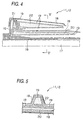
- each of the skins 11, 12 is formed by laminating composite prepreg 18 like a thermosetting carbon-fiber reinforced plastic (CFRP), for instance, on a steel skin forming jig 17 having a surface corresponding to the outer contours of the airfoil, placing an intra-skin foam core 20 whose outer surface is covered with a glue film 19 like a thermosetting film, for instance, on the upper surface of the composite prepreg 18 laminate, laminating again composite prepreg 18 on top, placing an intra-projection foam core 21 covered with a glue film 19 on top, laminating again composite prepreg 18 on top, placing intra-rib foam cores 22 covered with a glue film 19 on top, laminating yet again composite prepreg 18 on top, and then hardening the entire assembly by application of heat.
- CFRP thermosetting carbon-fiber reinforced plastic
- the individual foam cores 20, 21, 22 used are foam cores which have been subjected to postcuring operation (one form of heat treatment) to reduce deformation which may occur while they are molded under heat.
- the intra-projection foam core 21 and the intra-rib foam cores 22 are formed into a rodlike structure having a trapezoidal cross section as shown in FIGS. 4 and 5. These foam cores 21, 22 improve overall strength as they are combined with the intra-skin foam core 20 and prevent stress concentration.
- the skins 11, 12 thus formed are set such that end surfaces of their ribs 14 and elongate projections 15 align face to face, and joined together using the adhesive, as shown in FIGS. 1 and 2.
- the spar 13 is made up of flanges 13a located on both sides and a web 13b which together form a U-shaped cross section as shown in FIGS. 1 and 2.
- the flanges 13a on both sides are bonded to the individual skins 11, 12 by the adhesive.
- the web 13b is bonded to the elongate projections 15 of both skins 11, 12 by the adhesive.
- the spar 13 is produced by laminating composite prepreg like a thermosetting CFRP, for instance, shaping the composite prepreg laminate into a U-shaped cross section, and then hardening it by heat.
- the upper skin 11, the lower skin 22 and the spar 13 are formed individually.
- each skin 11, 12 the composite prepreg 18 like a 180°C-hardening CFRP, for instance, is laminated on the skin forming jig 17 having a surface corresponding to the outer contours of the airfoil, the intra-skin foam core 20 whose outer surface is covered with the glue film 19 like a 180°C-hardening film, for instance, is placed on the upper surface of the composite prepreg 18 laminate, and the composite prepreg 18 is laminated again on top as shown in FIGS. 4 and 5.
- the skins are formed in this manner.
- the intra-projection foam core 21 is covered with the glue film 19 and placed on the upper surface, and the composite prepreg 18 is laminated again on top. Consequently, the elongate projection 15 is formed.
- the intra-rib foam cores 22 are covered with the glue film 19 and placed on the upper surface, and the composite prepreg 18 is laminated yet again on top. Consequently, the ribs 14 are formed.
- a jig 23 made of steel, for instance, for keeping a surface to be bonded to the spar 13 in flat shape is placed at the front side of the elongate projection 15
- a jig 24 made of CFRP for instance, for keeping skin bonding surfaces in flat shape is placed on the end surfaces of the ribs 14 and elongate projections 15, and
- a caul plate 25 made of aluminum, for instance, for forming a trailing edge flat surface is placed at the rear end of the laminated assembly, as shown in FIGS. 6 to 8.
- each skin 11, 12 is molded under heat at a temperature of 180°C under a pressure of 3.2 atmospheres in an autoclave.
- the spar 13 is formed as follows.
- Composite prepreg formed of a thermosetting CFRP, for instance, is laminated and a resultant laminate, formed into a U-shaped cross-sectional shape, is molded under heat at a temperature of 180°C under a pressure of 3.2 atmospheres in the autoclave to produce the spar 13.
- a pasty thermosetting adhesive 16 (which cures at 120°C, for example) is applied to bond surfaces of the two skins 11, 12 and those of the spar 13, and the same adhesive 16 is applied to outer surfaces of the two flanges 13a and the web 13b of the spar 13 as shown in FIGS. 9 and 10. Then, these components are bonded simultaneously to together form a single structure.
- FIGS. 11 and 12 show an example of a bonding jig used for bonding operation, in which the bonding jig 30 has a base 31, a pair of face plates 33 mounted on the base 31 by supports 32, together forming a V shape, and wedge-shaped load application blocks 34.
- the two skins 11, 12 and the spar 13 to which the adhesive 16 has been applied are inserted into a space between the two face plates 33 from above in a temporarily bonded condition and pressed by the load application blocks 34 placed on the spar 13.
- the skins 11, 12 and the spar 13 are bonded to form the single structure as they are heated at a temperature of 120°C under pressure exerted by the blocks 34.
- the ribs 14 and the elongate projection 15 are formed as integral part of each skin 11, 12 as described above, the number of principal constituent components is reduced. Since the assembling components like fasteners are not required as a consequence, it is possible to achieve cost reduction.
- foam cores 20, 21, 22 having isotropic mechanical properties are used as core material and these foam cores are postcured, it is possible to reduce deformation which may occur while they are molded under heat even when each skin 11, 12 is one-piece molded together with the ribs 14 and the elongate projection 15.
- the jigs 23, 24 and the caul plate 25 are placed on the adhesive bond areas of each skin 11, 12 prior to their molding operation under heat, it is possible to significantly improve the accuracy of their bond surfaces. In particular, it become no longer necessary to adjust mating surfaces of the individual ribs 14 one by one in adhesive assembly operation and this serves to simplify mating surface adjustment.
- the spar 13 is formed into a U-shaped cross-sectional shape, it can be produced at a lower cost compared to those having an I-shaped cross section. Moreover, since not only the web 13b but also the flanges 13a on both sides of the spar 13 are bonded to the respective skins 11, 12, it is possible to obtain an adhesive strength equivalent to the adhesive strength achieved by the spars having the I-shaped cross section.
- the individual ribs 14 have a trapezoidal cross section as shown in FIGS. 13(a) and 13(b), their left and right inclined surfaces can evenly support a peeling load. Due to this trapezoidal cross-sectional shape, combined with the fact that the individual skins 11, 12 has high stiffness and the amount of their deformation is small, it is possible to alleviate stress concentration. Moreover, although the extreme end surfaces of the ribs 14 of the individual skins 11, 12 are bonded face to face, it is possible to obtain a sufficient peeling strength since the peeling load is evenly supported by the left and right inclined surfaces of each rib 14.
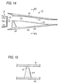
- FIGS. 14 and 15 are diagrams showing a second embodiment of the invention, in which the upper skin 11 and the lower skin 12 of the first embodiment are replaced by an upper skin 41 and a lower skin 42.
- the upper skin 41 is constructed of a skin portion alone, while the lower skin 42 is constructed of a skin portion and large-sized ribs 44 and elongate projection 45 which are one-piece formed with the skin portion, as shown in FIGS. 14 and 15.
- This embodiment otherwise has the same construction and functional features as the earlier-described first embodiment.
- the present embodiment has an advantage over the first embodiment in terms of cost when applied to a box-structure airfoil 10 having a relatively small thickness, because it is advantageous in that the upper skin 41 is made into a simple shape.
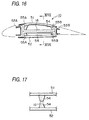
- FIGS. 16 to 18 are diagrams showing a third embodiment of the invention which is so configured that a box-structure airfoil 10 can be used as a horizontal stabilizer of an aircraft.
- this box-structure airfoil 10 is constructed of an upper skin 51, a lower skin 52, a front spar 53A and a rear spar 53B, in which ribs 54, a front elongate projection 55A for bonding the front spar 53A and a rear elongate projection 55B for bonding the rear spar 53B are formed integrally on the inner surface of each skin 51, 52, as shown in FIG. 16.
- This embodiment otherwise has the same construction and functional features as the earlier-described first embodiment.
- ribs and elongate projection are one-piece molded together with a skin member in this invention as thus far described, it is possible to reduce the number of principal constituent components as well as the number of assembling components like fasteners. As a consequence, it is possible to achieve cost reduction. Further, since individual flanges of a spar are bonded to individual skin members, it is possible to obtain a peeling strength equivalent to that achieved when using a spar having an I-shaped cross section even when the spar having a U-shaped cross section is used to achieve cost reduction.
- the ribs and elongate projection are formed integrally with one skin and their extreme ends are bonded to the other skin. Therefore, the shape of the second skin can be simplified and, in particular, it is possible to achieve cost reduction when the invention is applied to a box-structure airfoil having a small thickness.
- the ribs and elongate projection are formed integrally with each skin and their extreme ends are bonded to one another. This makes it possible to reduce dimensions of the ribs and elongate projection rising out of each skin even when the invention is applied to a box-structure airfoil having a large thickness. Furthermore, such skins are easy to manufacture and it is possible to improve the overall strength of each skin as it is one-piece formed with the ribs and elongate projection.
- a box-structure airfoil is manufactured by a molding process in which a spar and individual skin members are separately formed and a bonding process in which bonding between extreme ends of the ribs and elongate projection and the first skin member, bonding between individual flanges of the spar and the individual skins, and bonding between a web of the spar and the elongate projection are simultaneously done by using an adhesive to thereby form a single structure.
- the first skin is formed by laminating composite material prepreg on a mold base having the same outer contours as the airfoil, placing a foam core covered with a glue film on an upper surface of the prepreg, laminating again composite material prepreg on top, and hardening an entire assembly by thermosetting operation.
- the foam core as core material, pressures are uniformly allocated during a hardening process unlike the case in which an anisotropic core material like a honeycomb panel is used.
- the foam core is covered with the glue film, it is possible to improve adhesion between the foam core and the prepreg.
- the second skin is formed by laminating composite material prepreg on a mold base having the same outer contours as the airfoil, placing a foam core covered with a glue film on the upper surface of the prepreg, laminating again composite material prepreg on top, placing an intra-projection foam core covered with a glue film on top, laminating again composite material prepreg on top, placing intra-rib foam cores covered with a glue film on top, laminating yet again composite material prepreg on top, and then hardening an entire assembly by thermosetting operation.
- the second skin is one-piece molded with the ribs and elongate projection, making it possible to reduce the number of principal constituent components.
- a box-structure airfoil is manufactured by a molding process in which a spar and individual skins are separately formed, and a bonding process in which bonding between extreme ends of ribs and elongate projections of the individual skins, bonding between individual flanges of the spar and the individual skins, and bonding between a web of the spar and the elongate projections of both skins are simultaneously done by using an adhesive to thereby form a single structure. Since the ribs and elongate projection are integrally formed in halves on each skin, their dimensions rising out of each skin are reduced even when the box-structure airfoil is of a type having a large thickness. Furthermore, the individual skins can be easily formed and it is possible to improve the overall strength of each skin as it is one-piece formed with the ribs and elongate projection.
- each of the first and second skins is formed by laminating composite material prepreg on a mold base having the same outer contours as the airfoil, placing a foam core covered with a glue film on the upper surface of the prepreg, laminating again composite material prepreg on top, placing an intra-projection foam core covered with a glue film on top, laminating again composite material prepreg on top, placing intra-rib foam cores covered with a glue film on top, laminating yet again composite material prepreg on top, and then hardening an entire assembly by thermosetting operation.
- this arrangement it is possible to reduce deformation during the thermosetting operation even when the ribs and elongate projection are one-piece molded with each skin.
- pressure plates are placed at least on end surfaces of the ribs and elongate projection prior to the thermosetting operation, the pressure plates having shapes corresponding to the shapes of mating bond surfaces.
- thermosetting adhesive Since a pasty thermosetting adhesive is used as the adhesive in this invention, a gap, whichever created between bond surfaces, is filled with the adhesive and this makes it possible to prevent a reduction in strength almost completely.
Landscapes
- Engineering & Computer Science (AREA)
- Mechanical Engineering (AREA)
- Aviation & Aerospace Engineering (AREA)
- Lining Or Joining Of Plastics Or The Like (AREA)
- Moulding By Coating Moulds (AREA)
- Laminated Bodies (AREA)
Applications Claiming Priority (2)
| Application Number | Priority Date | Filing Date | Title |
|---|---|---|---|
| JP21541398 | 1998-07-30 | ||
| JP10215413A JP2000043796A (ja) | 1998-07-30 | 1998-07-30 | 複合材の翼形構造およびその成形方法 |
Publications (2)
| Publication Number | Publication Date |
|---|---|
| EP0976650A2 true EP0976650A2 (fr) | 2000-02-02 |
| EP0976650A3 EP0976650A3 (fr) | 2002-06-05 |
Family
ID=16671926
Family Applications (1)
| Application Number | Title | Priority Date | Filing Date |
|---|---|---|---|
| EP99115003A Withdrawn EP0976650A3 (fr) | 1998-07-30 | 1999-07-30 | Structure en composite pour aéronef et procédé pour sa fabrication |
Country Status (3)
| Country | Link |
|---|---|
| US (2) | US6234423B1 (fr) |
| EP (1) | EP0976650A3 (fr) |
| JP (1) | JP2000043796A (fr) |
Cited By (5)
| Publication number | Priority date | Publication date | Assignee | Title |
|---|---|---|---|---|
| US6386481B1 (en) | 2001-01-08 | 2002-05-14 | Patria Finavicomp Oy | Arrangement for fastening stringers to aircraft wing ribs |
| EP1288124A1 (fr) * | 2001-09-03 | 2003-03-05 | Fuji Jukogyo Kabushiki Kaisha | Méthode de fabrication d'une aile en matériau composite et une aile en matériau composite |
| WO2008105806A3 (fr) * | 2006-10-26 | 2009-06-11 | Boeing Co | Structure de panneau d'aile |
| EP2735504A1 (fr) * | 2012-11-22 | 2014-05-28 | Airbus Operations S.L. | Structure hautement intégrée comprenant des nervures de bord d'attaque et de fuite d'une surface portante d'un aéronef |
| CN115742343A (zh) * | 2022-11-11 | 2023-03-07 | 航天特种材料及工艺技术研究所 | 一种榫卯连接的复合材料翼面及其成型方法 |
Families Citing this family (78)
| Publication number | Priority date | Publication date | Assignee | Title |
|---|---|---|---|---|
| US7681835B2 (en) * | 1999-11-18 | 2010-03-23 | Rocky Mountain Composites, Inc. | Single piece co-cure composite wing |
| US6889937B2 (en) * | 1999-11-18 | 2005-05-10 | Rocky Mountain Composites, Inc. | Single piece co-cure composite wing |
| DE60128664T2 (de) * | 2000-04-05 | 2008-01-31 | Bell Helicopter Textron, Inc., Fort Worth | Gestaltung eines holmes in k-form für eine geklebte flügelstruktur |
| JP4526698B2 (ja) * | 2000-12-22 | 2010-08-18 | 富士重工業株式会社 | 複合材成形品及びその製造方法 |
| ATE284346T1 (de) * | 2001-01-26 | 2004-12-15 | Fischer Adv Components Gmbh | Einrichtung zum verbinden beweglicher teile mit strukturbauteilen von flugzeugen od. dgl. |
| DE10156733B4 (de) * | 2001-11-19 | 2006-04-20 | Eads Deutschland Gmbh | Aerodynamisches Profil mit verstellbarer Klappe |
| US7204951B2 (en) * | 2002-07-30 | 2007-04-17 | Rocky Mountain Composites, Inc. | Method of assembling a single piece co-cured structure |
| DE502004007968D1 (de) * | 2003-07-08 | 2008-10-16 | Airbus Gmbh | Leichtbaustruktur |
| US20050230036A1 (en) * | 2004-04-16 | 2005-10-20 | John Lampl | Lightweight airfoil and method of manufacturing same |
| US20060027308A1 (en) * | 2004-08-05 | 2006-02-09 | Mackenzie M S | Method and apparatus for curing patches on composite structures having complex substrates |
| FI118122B (fi) * | 2004-10-08 | 2007-07-13 | Patria Aerostructures Oy | Ilma-aluksen kääntyvä paneeli ja komposiittirakenteinen tukikappale |
| US7247002B2 (en) * | 2004-12-02 | 2007-07-24 | Siemens Power Generation, Inc. | Lamellate CMC structure with interlock to metallic support structure |
| US7316539B2 (en) * | 2005-04-07 | 2008-01-08 | Siemens Power Generation, Inc. | Vane assembly with metal trailing edge segment |
| US7393184B2 (en) * | 2005-11-10 | 2008-07-01 | General Electric Company | Modular blades and methods for making same |
| US7753313B1 (en) * | 2006-09-19 | 2010-07-13 | The Boeing Company | Composite wing slat for aircraft |
| CA2685478C (fr) * | 2007-04-30 | 2012-08-14 | Airbus Operations, S.L. | Caisson de torsion multi-longerons integre en materiau composite |
| US20080277531A1 (en) * | 2007-05-11 | 2008-11-13 | The Boeing Company | Hybrid Composite Panel Systems and Methods |
| US7861969B2 (en) * | 2007-05-24 | 2011-01-04 | The Boeing Company | Shaped composite stringers and methods of making |
| ITTO20070507A1 (it) * | 2007-07-11 | 2009-01-12 | Alenia Aeronautica Spa | Procedimento di fabbricazione di una struttura d'ala monolitica a profilo integrale |
| FR2918919B1 (fr) * | 2007-07-17 | 2013-03-29 | Eurocopter France | Procede et dispositif pour coller la coiffe metallique d'un bord d'attaque d'une voiture |
| FR2921899B1 (fr) * | 2007-10-04 | 2011-04-15 | Airbus France | Procede de renforcement local d'un element en materiau composite, et caisson central de voilure pour aeronef renforce |
| US7871041B2 (en) * | 2007-10-17 | 2011-01-18 | Lockheed Martin Corporation | System, method, and apparatus for leading edge structures and direct manufacturing thereof |
| US7879276B2 (en) * | 2007-11-08 | 2011-02-01 | The Boeing Company | Foam stiffened hollow composite stringer |
| WO2010048370A1 (fr) * | 2008-10-22 | 2010-04-29 | Vec Industries, L.L.C. | Aube d'éolienne et son procédé de fabrication |
| US8510947B2 (en) * | 2008-11-14 | 2013-08-20 | General Electric Company | Turbine blade fabrication |
| US8540921B2 (en) * | 2008-11-25 | 2013-09-24 | The Boeing Company | Method of forming a reinforced foam-filled composite stringer |
| ES2372828B1 (es) * | 2008-12-17 | 2012-12-13 | Airbus Operations, S.L. | Costilla-herraje. |
| US8177513B2 (en) * | 2009-02-18 | 2012-05-15 | General Electric Company | Method and apparatus for a structural outlet guide vane |
| US8105042B2 (en) * | 2009-04-06 | 2012-01-31 | United Technologies Corporation | Intermediate-manufactured composite airfoil and methods for manufacturing |
| US8857128B2 (en) * | 2009-05-18 | 2014-10-14 | Apple Inc. | Reinforced device housing |
| CN102427999B (zh) * | 2009-05-28 | 2015-11-25 | 洛林航空工程公司 | 用于飞行器元件尾缘的复合结构面板以及制造该面板的方法 |
| FR2954269B1 (fr) * | 2009-12-18 | 2012-12-28 | Lorraine Construction Aeronautique | Pannneau structurant composite de bord de fuite pour element d'aeronef |
| US8500066B2 (en) * | 2009-06-12 | 2013-08-06 | The Boeing Company | Method and apparatus for wireless aircraft communications and power system using fuselage stringers |
| US8570152B2 (en) * | 2009-07-23 | 2013-10-29 | The Boeing Company | Method and apparatus for wireless sensing with power harvesting of a wireless signal |
| US8617687B2 (en) * | 2009-08-03 | 2013-12-31 | The Boeing Company | Multi-functional aircraft structures |
| US20110054850A1 (en) * | 2009-08-31 | 2011-03-03 | Roach James T | Composite laminate construction method |
| US10137542B2 (en) | 2010-01-14 | 2018-11-27 | Senvion Gmbh | Wind turbine rotor blade components and machine for making same |
| CN102762850B (zh) | 2010-01-14 | 2015-04-08 | 耐普迪考股份有限公司 | 风力涡轮机转子叶片部件及其制造方法 |
| US8511498B2 (en) * | 2010-01-25 | 2013-08-20 | Apple Inc. | Method for manufacturing an electronic device enclosure |
| US8408972B2 (en) * | 2010-01-25 | 2013-04-02 | Apple Inc. | Apparatus and method for intricate cuts |
| US8201776B1 (en) | 2010-02-17 | 2012-06-19 | Horizon Hobby, Inc. | Airfoils and method for constructing airfoils |
| US8372495B2 (en) | 2010-05-26 | 2013-02-12 | Apple Inc. | Electronic device enclosure using sandwich construction |
| US9120272B2 (en) | 2010-07-22 | 2015-09-01 | Apple Inc. | Smooth composite structure |
| WO2012082668A2 (fr) * | 2010-12-13 | 2012-06-21 | 3M Innovative Properties Company | Film à motifs et articles réalisés à partir de celui-ci |
| US9011623B2 (en) | 2011-03-03 | 2015-04-21 | Apple Inc. | Composite enclosure |
| US8262362B2 (en) | 2011-06-08 | 2012-09-11 | General Electric Company | Wind turbine blade shear web with spring flanges |
| US8235671B2 (en) | 2011-07-19 | 2012-08-07 | General Electric Company | Wind turbine blade shear web connection assembly |
| US8393871B2 (en) | 2011-07-19 | 2013-03-12 | General Electric Company | Wind turbine blade shear web connection assembly |
| US8257048B2 (en) * | 2011-07-19 | 2012-09-04 | General Electric Company | Wind turbine blade multi-component shear web with intermediate connection assembly |
| ES2606591T3 (es) * | 2012-11-21 | 2017-03-24 | Airbus Operations S.L. | Un cajón de torsión optimizado para una aeronave |
| IL223443A (en) | 2012-12-04 | 2014-06-30 | Elbit Systems Cyclone Ltd | Buildings from composite materials with integral composite connectors and manufacturing methods |
| US8973871B2 (en) | 2013-01-26 | 2015-03-10 | The Boeing Company | Box structures for carrying loads and methods of making the same |
| US10407955B2 (en) | 2013-03-13 | 2019-09-10 | Apple Inc. | Stiff fabric |
| US9738375B2 (en) * | 2013-12-05 | 2017-08-22 | The Boeing Company | One-piece composite bifurcated winglet |
| TWI626345B (zh) | 2013-12-20 | 2018-06-11 | 蘋果公司 | 編織物條帶、產生用於一編織物條帶之一固定機構的方法及用於產生用於固定至一物件之一編織物條帶的方法 |
| ES2755765T3 (es) * | 2013-12-23 | 2020-04-23 | Airbus Operations Sl | Superficie de control de aeronave |
| AT516211A1 (de) * | 2014-08-11 | 2016-03-15 | Facc Ag | Steuerflächenelement |
| ES2729104T3 (es) | 2014-09-29 | 2019-10-30 | Boeing Co | Largueros de relanzamiento para aplicaciones de timón y elevador |
| JP2016150561A (ja) * | 2015-02-19 | 2016-08-22 | 積水化成品工業株式会社 | 繊維強化複合体、及び、繊維強化複合体の製造方法 |
| AT517198B1 (de) | 2015-04-24 | 2021-12-15 | Facc Ag | Steuerflächenelement für ein Flugzeug |
| GB2542435A (en) * | 2015-09-21 | 2017-03-22 | Charles Elson Andrew | Foam aerofoil |
| US10207471B2 (en) * | 2016-05-04 | 2019-02-19 | General Electric Company | Perforated ceramic matrix composite ply, ceramic matrix composite article, and method for forming ceramic matrix composite article |
| WO2018001425A1 (fr) * | 2016-06-28 | 2018-01-04 | Vestas Wind Systems A/S | Fabrication d'une pale d'éolienne |
| CN106585955B (zh) * | 2016-12-09 | 2023-06-06 | 中国计量大学 | 无人机机翼一体复合梁结构及其制造方法 |
| US10570879B2 (en) | 2017-05-23 | 2020-02-25 | General Electric Company | Joint assembly for a wind turbine rotor blade with flanged bushings |
| US10647406B2 (en) | 2017-06-01 | 2020-05-12 | The Boeing Company | Closed-angle composite airfoil spar and method of fabricating the same |
| US10563636B2 (en) | 2017-08-07 | 2020-02-18 | General Electric Company | Joint assembly for a wind turbine rotor blade |
| US10864686B2 (en) | 2017-09-25 | 2020-12-15 | Apple Inc. | Continuous carbon fiber winding for thin structural ribs |
| US11358348B2 (en) * | 2019-01-02 | 2022-06-14 | The Boeing Company | Mold insert for use with a mandrel for forming a composite structure |
| GB2583134B (en) * | 2019-04-18 | 2021-11-24 | Fokker Aerostructures Bv | Hinge structure |
| CN110481811B (zh) * | 2019-08-29 | 2022-07-05 | 广联航空工业股份有限公司 | 一种无人机机翼整体共固化成型方法 |
| US20210362828A1 (en) * | 2020-05-21 | 2021-11-25 | The Boeing Company | Structural composite airfoils with directly coupled front spars, and related methods |
| US11981426B2 (en) | 2021-01-05 | 2024-05-14 | The Boeing Company | Composite spars with integrated sacrificial surfaces |
| US11673644B2 (en) * | 2021-01-05 | 2023-06-13 | The Boeing Company | Composite spars with integrated sacrificial surfaces |
| CN113290872B (zh) * | 2021-03-31 | 2022-04-08 | 成都飞机工业(集团)有限责任公司 | 一种预先发泡定位夹芯后校验组合件的胶接方法 |
| US11498656B1 (en) * | 2021-04-26 | 2022-11-15 | Rohr, Inc. | Airfoil system with embedded electric device |
| CN113602477B (zh) * | 2021-07-26 | 2024-03-15 | 成都飞机工业(集团)有限责任公司 | 一种全复合材料的尾翼结构及其成型方法 |
| CN113602474B (zh) * | 2021-08-16 | 2023-09-29 | 中国商用飞机有限责任公司北京民用飞机技术研究中心 | 一种热塑性复合材料机翼油箱盒段及其制造方法 |
Citations (1)
| Publication number | Priority date | Publication date | Assignee | Title |
|---|---|---|---|---|
| EP0485027A2 (fr) | 1990-11-09 | 1992-05-13 | British Aerospace Public Limited Company | Fabrication d'une aile en matériau composite de fibres de carbone |
Family Cites Families (13)
| Publication number | Priority date | Publication date | Assignee | Title |
|---|---|---|---|---|
| US3643900A (en) * | 1970-03-02 | 1972-02-22 | John P Maloney | Jig panel for airfoil |
| US3768760A (en) * | 1970-10-30 | 1973-10-30 | Hercules Inc | Graphite fiber composite covering employing multi-directional |
| US3775238A (en) * | 1971-06-24 | 1973-11-27 | J Lyman | Structural composite material |
| US3995080A (en) * | 1974-10-07 | 1976-11-30 | General Dynamics Corporation | Filament reinforced structural shapes |
| US4009067A (en) * | 1975-07-07 | 1977-02-22 | Rogers Charles W | Process of fabricating composite structural members |
| US4095322A (en) * | 1976-08-30 | 1978-06-20 | The Boeing Company | Method of fabricating a composite aerodynamic rotorblade assembly |
| FR2440831A1 (fr) * | 1978-11-07 | 1980-06-06 | Dassault Avions | Panneaux a base de fibres a haute resistance, particulierement applicables a la construction des avions |
| DE3113079C2 (de) * | 1981-04-01 | 1985-11-21 | Messerschmitt-Bölkow-Blohm GmbH, 8000 München | Aerodynamischer Groß-Flügel und Verfahren zu dessen Herstellung |
| US4783228A (en) * | 1986-07-03 | 1988-11-08 | Lockheed Corporation | Method of bonding metal skins to internal support structures |
| JPH03104799A (ja) * | 1989-09-20 | 1991-05-01 | Fuji Heavy Ind Ltd | 複合材ブレードの製造方法 |
| US5224670A (en) * | 1991-09-13 | 1993-07-06 | Grumman Aerospace Corporation | Composite focused load control surface |
| AT398064B (de) * | 1992-07-01 | 1994-09-26 | Hoac Austria Flugzeugwerk Wr N | Kunststoff-verbundprofil, insbesondere flügelholm für den flugzeugbau |
| US5807454A (en) * | 1995-09-05 | 1998-09-15 | Honda Giken Kogyo Kabushiki Kaisha | Method of maufacturing a leading edge structure for aircraft |
-
1998
- 1998-07-30 JP JP10215413A patent/JP2000043796A/ja active Pending
-
1999
- 1999-07-29 US US09/363,396 patent/US6234423B1/en not_active Expired - Fee Related
- 1999-07-30 EP EP99115003A patent/EP0976650A3/fr not_active Withdrawn
-
2001
- 2001-04-04 US US09/824,678 patent/US6689246B2/en not_active Expired - Fee Related
Patent Citations (2)
| Publication number | Priority date | Publication date | Assignee | Title |
|---|---|---|---|---|
| EP0485027A2 (fr) | 1990-11-09 | 1992-05-13 | British Aerospace Public Limited Company | Fabrication d'une aile en matériau composite de fibres de carbone |
| US5216799A (en) | 1990-11-09 | 1993-06-08 | British Aerospace Public Limited Company | Carbon fibre composite wing manufacture |
Cited By (7)
| Publication number | Priority date | Publication date | Assignee | Title |
|---|---|---|---|---|
| US6386481B1 (en) | 2001-01-08 | 2002-05-14 | Patria Finavicomp Oy | Arrangement for fastening stringers to aircraft wing ribs |
| EP1288124A1 (fr) * | 2001-09-03 | 2003-03-05 | Fuji Jukogyo Kabushiki Kaisha | Méthode de fabrication d'une aile en matériau composite et une aile en matériau composite |
| WO2008105806A3 (fr) * | 2006-10-26 | 2009-06-11 | Boeing Co | Structure de panneau d'aile |
| US7628358B2 (en) | 2006-10-26 | 2009-12-08 | The Boeing Company | Wing panel structure |
| EP2735504A1 (fr) * | 2012-11-22 | 2014-05-28 | Airbus Operations S.L. | Structure hautement intégrée comprenant des nervures de bord d'attaque et de fuite d'une surface portante d'un aéronef |
| US9381991B2 (en) | 2012-11-22 | 2016-07-05 | Airbus Operations S.L. | Highly integrated structure including leading and trailing edge ribs for an aircraft lifting surface |
| CN115742343A (zh) * | 2022-11-11 | 2023-03-07 | 航天特种材料及工艺技术研究所 | 一种榫卯连接的复合材料翼面及其成型方法 |
Also Published As
| Publication number | Publication date |
|---|---|
| US6689246B2 (en) | 2004-02-10 |
| EP0976650A3 (fr) | 2002-06-05 |
| JP2000043796A (ja) | 2000-02-15 |
| US20010017336A1 (en) | 2001-08-30 |
| US6234423B1 (en) | 2001-05-22 |
Similar Documents
| Publication | Publication Date | Title |
|---|---|---|
| US6689246B2 (en) | Method of making composite airfoil structures | |
| JP4416900B2 (ja) | 複合材パネルおよびその製造方法 | |
| JP4574086B2 (ja) | 複合材翼の製造方法および複合材翼 | |
| US9352822B2 (en) | Bonded composite airfoil | |
| US6561459B2 (en) | Method of fabricating a wing of composite material | |
| US6743504B1 (en) | Co-cured composite structures and method of making them | |
| CN102448814B (zh) | 飞机压力隔墙组装结构 | |
| KR102047554B1 (ko) | 복합재 햇 보강재, 복합재 햇-보강 압력 웨브, 및 그 제조 방법 | |
| US2479342A (en) | Composite structure for use in aircraft construction | |
| US7097731B2 (en) | Method of manufacturing a hollow section, grid stiffened panel | |
| EP1145828A2 (fr) | Procédé pour la fabrication d'une structure composite et structure composite ainsi obtenue | |
| US5849393A (en) | Structural element and method of making | |
| US7238409B1 (en) | Structural element with rib-receiving member | |
| JP2012511119A5 (fr) | ||
| JP4545339B2 (ja) | 複合材翼およびその製造方法 | |
| JPH058316A (ja) | 複合材製構造体の製造方法 | |
| JPS6323040B2 (fr) | ||
| US11400662B2 (en) | Method for manufacturing a stiffened structural panel for an aircraft | |
| JP2517634B2 (ja) | 複合材料製品の成形方法 | |
| KR100254259B1 (ko) | 경항공기용 미익의 제작방법 | |
| JP2002347149A (ja) | 複合材ハニカムサンドイッチ構造体及びその製造方法 | |
| CN119370356B (zh) | 一种翼段连接端肋及其制造方法 | |
| CN118306030A (zh) | 一种碳纤维复合材料水上无人机加筋壁板的制造方法 | |
| JPS624218B2 (fr) | ||
| JPH07117789A (ja) | 繊維強化樹脂製翼およびその製造方法 |
Legal Events
| Date | Code | Title | Description |
|---|---|---|---|
| PUAI | Public reference made under article 153(3) epc to a published international application that has entered the european phase |
Free format text: ORIGINAL CODE: 0009012 |
|
| AK | Designated contracting states |
Kind code of ref document: A2 Designated state(s): AT BE CH CY DE DK ES FI FR GB GR IE IT LI LU MC NL PT SE |
|
| AX | Request for extension of the european patent |
Free format text: AL;LT;LV;MK;RO;SI |
|
| PUAL | Search report despatched |
Free format text: ORIGINAL CODE: 0009013 |
|
| AK | Designated contracting states |
Kind code of ref document: A3 Designated state(s): AT BE CH CY DE DK ES FI FR GB GR IE IT LI LU MC NL PT SE |
|
| AX | Request for extension of the european patent |
Free format text: AL;LT;LV;MK;RO;SI |
|
| AKX | Designation fees paid | ||
| REG | Reference to a national code |
Ref country code: DE Ref legal event code: 8566 |
|
| STAA | Information on the status of an ep patent application or granted ep patent |
Free format text: STATUS: THE APPLICATION IS DEEMED TO BE WITHDRAWN |
|
| 18D | Application deemed to be withdrawn |
Effective date: 20021206 |