EP0977211A2 - Electrical component with a restriction in a PTC polymer element - Google Patents
Electrical component with a restriction in a PTC polymer element Download PDFInfo
- Publication number
- EP0977211A2 EP0977211A2 EP99810624A EP99810624A EP0977211A2 EP 0977211 A2 EP0977211 A2 EP 0977211A2 EP 99810624 A EP99810624 A EP 99810624A EP 99810624 A EP99810624 A EP 99810624A EP 0977211 A2 EP0977211 A2 EP 0977211A2
- Authority
- EP
- European Patent Office
- Prior art keywords
- electrical component
- constrictions
- constriction
- component according
- ptc polymer
- Prior art date
- Legal status (The legal status is an assumption and is not a legal conclusion. Google has not performed a legal analysis and makes no representation as to the accuracy of the status listed.)
- Withdrawn
Links
Images

Classifications
-
- H—ELECTRICITY
- H01—ELECTRIC ELEMENTS
- H01C—RESISTORS
- H01C7/00—Non-adjustable resistors formed as one or more layers or coatings; Non-adjustable resistors made from powdered conducting material or powdered semi-conducting material with or without insulating material
- H01C7/02—Non-adjustable resistors formed as one or more layers or coatings; Non-adjustable resistors made from powdered conducting material or powdered semi-conducting material with or without insulating material having positive temperature coefficient
- H01C7/028—Non-adjustable resistors formed as one or more layers or coatings; Non-adjustable resistors made from powdered conducting material or powdered semi-conducting material with or without insulating material having positive temperature coefficient consisting of organic substances
Definitions
- the present invention relates to an electrical component with a PTC polymer element.
- Such components are e.g. B. known from EP 0 655 760 A2, according to which a PTC polymer element is used for overcurrent limitation and the PTC polymer element for this purpose in series with a switch disconnector is interconnected.
- a current over one by designing the PTC polymer element certain threshold value creates a fast non-linear increase in the electrical resistance of the PTC polymer element and thereby limits the overcurrents.
- the switch disconnector can then completely interrupt the limited current.
- PTC polymer element and PTC polymer material also such elements and includes materials that contain components without PTC behavior, for example linear resistance elements or varistor elements added are.
- this invention relates to such an electrical component, in which the PTC polymer element does not have a constant current-carrying cross-sectional area has, but constricted the line cross-sectional area is.
- the main flow direction defining this cross-sectional area is in general by external contacts on the PTC polymer element or by given the geometry. However, it does not have to occur to everyone correspond to local current directions, but only to a certain extent Average.
- the current density locally increased relative to the rest of the PTC polymer element, so that predetermined is at which point the non-linear increase in resistance of the PTC effect begins when the corresponding current threshold values are reached.
- EP 0 798 750 A2 again shows a resistance system made of a PTC polymer element with varistor elements, in which such constrictions are provided are.
- U.S. Patent 3,351,882 also shows constricted PTC polymer elements, with the justification given here that by suitable Choice of constrictions overheating near the contact points of the PTC polymer element should be avoided.
- the European patent EP 0 should also be mentioned as prior art 038 715 B1, in which a specific design of a PTC polymer element with a constriction a very quick response within a few seconds or less.
- a PTC polymer element with a constriction is also shown in JP 4-130602 with patent abstract, DE 196 26 238 A1 and the US patents 4,317,027 and 4,352,083.
- the latter two publications show in particular that constrictions due to adjacent recesses can be formed in a PTC polymer material.
- the present Invention based on the technical problem of an electrical component with a Specify PTC polymer element in which the PTC polymer element particularly quick response and in the normally conductive case one good current carrying capacity as well as a reliable and permanent one Operation shows.
- the invention provides an electrical component with a PTC polymer element before that a constriction of the cross-sectional area perpendicular to a main flow direction, an opening angle of Constriction in a longitudinal section plane containing the main flow direction is at least 100 °.
- the invention thus relates to PTC polymer elements in which the State of the art constriction known per se runs particularly steeply, thus has a particularly large opening angle.
- the constriction is limited only the cross-sectional area is formed in one direction, the PTC polymer element So it has a two-dimensional basic structure, so to speak.
- the definition of the invention relates to an opening angle in a longitudinal section plane containing the main flow direction through the PTC polymer element.
- the invention relates to PTC polymer elements in which the value of 100 ° for the Opening angle reached or exceeded in at least one longitudinal section plane becomes.
- the opening angle is defined from the perspective of the point with minimal Cross-section in the constriction, i.e. in the sense of widening starting from the point of minimal cross-section.
- the right and left opening angles are combined on one side to a total opening angle of at least 100 °, however occurs in two parts at different vertices.
- the Vertices of the two parts of the opening angle due to the transverse expansion the minimum cross-sectional area in the considered longitudinal section plane separated from each other. It is not necessary that the two parts of the total opening angle are identical, but preferred.
- the (sum) opening angle must be of the minimum Cross-sectional area seen from at least one of the two sides , but preferably applies to both sides.
- Route sections angled to the main flow direction on both sides of the constriction do not necessarily have to be regularly shaped. It is sufficient, if a route section fulfilling the angular condition according to the invention can be defined as the mean. However, it is preferred that the constriction flanks essentially on both sides of the minimum cross-sectional area are straight and thus essentially the opening angle as a whole define without averaging. Then it cannot be clear local deviations from the steep formation preferred according to the invention the constriction.
- the mentioned value of 100 ° for the total opening angle (e.g. a Partial opening angle on the right of 50 ° and a partial opening angle on the left of 50 °) forms the lower bound for the invention. In fact, however, are still larger opening angles are cheaper, so opening angles are increasingly preferred from Z. B. 105 °, 110 °, 115 ° or 120 ° and above.
- Another important aspect of the invention is that with the values according to the invention for the opening angle with good current carrying capacity attractive constrictions can be produced so quickly, that with a series connection of at least two such constrictions even without parallel connection of a varistor or resistance element simultaneous response is guaranteed and therefore really a multiplication the respective dielectric strength of a constriction is possible.
- the PTC materials are apparently one certain inherent inertia regarding the heat transfer from the typically conductive particles present in these PTC materials on the polymer matrix by its response to the temperature increase show the actual PTC effect. Is the response behavior significantly faster than this inherent sluggishness, so can really simultaneous response of serially connected points of contact or constrictions be guaranteed. This is a particularly important aspect of the invention because it is a theoretically unlimited increase the dielectric strength of the entire electrical component becomes possible.
- parallel connections are also provided preferred at least two of the constrictions.
- this has the advantage of better mechanical stability, especially with larger ones Total line cross-sectional areas.
- it results from the Allocation of the necessary line cross-sectional area to two or more parallel contact points also the advantage of an improved Cooling effect, d. H. a better thermal coupling of the contact points or the places of the minimum line cross-sectional area on the remaining volume of the PTC polymer element.
- the parallel connections and series connections can also be combined, resulting in a field of constrictions. This determines the extension (s) of the field transverse to the main flow direction the line cross-sectional area and together with others Parameters the current carrying capacity, while the "depth" of the field, ie the Series connection number that determines dielectric strength.
- Another aspect of the invention in turn relates to the dielectric strength, in this case, however, already related to the individual constriction.
- the invention provides, essentially in the main flow direction a bridge in the center of the constriction, i.e. a bridge with in essentially the minimum cross-sectional area of the constriction.
- This web should be extended so far in the main flow direction that - with a length depending on the respective parameters of the used PTC polymer material - a zone of high resistance completely can build up in the area of the minimum cross-sectional area.
- a range between 0.5 and 4 mm is typically preferred between 1 and 2 mm for the extension of the web in the main flow direction to provide.
- Bridge lengths that are too long are disadvantageous because they are for the Invention can deteriorate essential cooling effect.
- the line cross-sectional area perpendicular to the main current direction is relatively strong restrict, by at least a factor of 3, preferably 4 or 5.
- it is divided into at least two connected in parallel Constrictions for reasons of stability and also because of shorter thermal diffusion paths advantageous. This is especially true for very strong reductions in cross-sectional area.
- the working examples complete this point.
- the invention relates to an electrical component with a PTC polymer element.
- the exemplary embodiments show PTC polymer elements for electrical resistors as a concrete variant of a electrical component. These electrical resistors are used as current limiting devices in automatic circuit breakers. Other electrical Components can of course be made in a similar way with PTC polymer elements be provided to the PTC effect for certain electrotechnical To use purposes. Because electrical resistors with PTC polymer elements are state of the art in the following, only the PTC polymer elements themselves shown and explained. The connection to external contacts and the use in an external circuit are the Known specialist without further explanation.
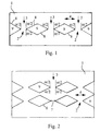
- FIG. 1 now shows a PTC polymer element 1, which is for a main flow direction 3 is designed, as indicated by the arrows, that is vertical in the figure from top to bottom (or bottom to top).
- Figure 1 shows a longitudinal sectional plane, the main flow direction 3 contains.
- this longitudinal section plane are horizontal in the sense of the figure three next to each other except for their respective position in the PTC polymer element 1 similar constrictions 2 are provided.
- These constrictions are formed by two diamond-shaped in the longitudinal section plane air-filled recesses 9 in solid material and two further recesses 9 right and left on the edge (in the sense of notches) of the solid material.
- the opening angle ⁇ which is essential according to the invention occurs, as already explained above, on both respective sides of a constriction 2 each in two parts, which are the same size in the present case.
- FIG. 2 shows a structure largely corresponding to FIG. 1, but in the case of the system shown in Figure 1 from constrictions 2 and recesses 9 provided twice and in the main flow direction 3 one behind the other is.
- the constrictions 2 and recesses 9 lie in the (vertical) Main flow direction 3 aligned one behind the other.
- the distance 10 between the locations of the smallest cross-sectional areas 7 in the main flow direction 3 the structure in FIG. 2 is approximately 8 mm apart. This distance of 8 mm is four times the minimum transverse expansion of the Constrictions 2 by 2 mm.
- FIG. 3 shows an exemplary embodiment that has been modified in three ways compared to FIG. 2.
- a series connection of two constrictions 2 a series connection of a plurality of constrictions 2 in each "pillar" of parallel connection has become, whereby only the top one four constrictions are shown.
- all largely sharp in the structures of FIG. 1 and FIG. 2 Corners somewhat rounded, what happens when machining a PTC polymer block or a mold for an injection or casting process Offers simplifications. These roundings do not change anything essential the functionality of the geometry shown.
- the locations of the minimum line cross-sectional area 7 are to be webs 5 extended, which extend over a distance 6 in the main flow direction 3. This can be seen better in the detail representation in FIG. 4.
- the length 6 of the webs 5 is 1 mm without the inclusion of the curve towards the opening angle, taking into account a part of this Curvature between 1-2 mm.
- the distance 10 is the Set minimum cross-section 7 in the main current direction 3 in this Embodiment 1 mm longer than in Figure 2, if one of each the center of the web calculated from; the web length is therefore in addition to this distance provided (add reference numeral 10).
- the remaining dimensions correspond to the values given above.
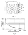
- FIG. 5 shows a top view of this figure, which corresponds identically as far as Figure 3.
- the surface is and corrugated the bottom of this PTC polymer element 1, d. H. has side Recesses or notches 11 also on the top and bottom on. Accordingly, there are also cutouts in this "third dimension" 12 in the solid material of the PTC polymer element 1.
- the wave-like recesses 11 on the top and bottom and the recesses 12 in solid material complete the cutouts already described with reference to FIGS.
- the PTC polymer element is made of ETTB from 50% ETFE and 50% TiB 2 .
- the material was milled or cut out of a block, but for large-scale production, various injection and casting processes according to the prior art are also conceivable.
- the corresponding metal contacts u. U. can be molded in one operation.
- FIGS. 3, 4 and 5 are compared to the Structures in Figures 1 and 2 by the formation of the constrictions 2 in the web shape described with regard to the dielectric strength in the response state improved.
- a typical value for a single constriction 2 is in the range of 150-300 V (rms value) depending on the material.
- a low voltage protection system in the Range of z. B. 690 V are accordingly several, a maximum of five serial interconnected constrictions 2 necessary.
- FIG. 6 shows measured values on a Experimental pattern of the structure of Figure 2, namely for the response time the ordinate versus the quotient from the actual load current and the maximum design current in the normally conductive state. It can be seen that the curve lengthened too much with small overcurrents Response times increases, so the PTC polymer element 1 in the range small multiple of the nominal current only responds slowly.
- This behavior is basically typical of PTC polymer materials; in the invention Pattern is the response behavior in the immediate vicinity, for example below 1.3 times the nominal current, but even slower than at conventional comparison pieces. This illustrates the improved cooling effect due to the geometry according to the invention, the permanent load near the rated current for a long time.
- the response behavior of the PTC polymer element according to the invention 1 above a value approximately 1.3 times to 2 times of the nominal current considerably faster, by 1-2 powers of ten faster than with conventional examples. This applies approximately until 100 times the nominal current; thereafter the pattern according to the invention is still better than the state of the art, but loses its lead.
Landscapes
- Engineering & Computer Science (AREA)
- Microelectronics & Electronic Packaging (AREA)
- Ceramic Engineering (AREA)
- Physics & Mathematics (AREA)
- Electromagnetism (AREA)
- Thermistors And Varistors (AREA)
Abstract
Description
Die vorliegende Erfindung bezieht sich auf ein elektrisches Bauteil mit einem
PTC-Polymerelement. Solche Bauteile sind z. B. bekannt aus der EP 0 655
760 A2, gemäß der ein PTC-Polymerelement zur Überstrombegrenzung verwendet
und das PTC-Polymerelement dazu mit einem Lasttrennschalter seriell
verschaltet wird. Ein Strom über einem durch die Auslegung des PTC-Polymerelements
bestimmten Schwellenwert erzeugt dabei ein schnelles
nichtlineares Ansteigen des elektrischen Widerstandes des PTC-Polymerelements
und begrenzt dadurch die Überströme. Der Lasttrennschalter
kann den begrenzten Strom dann vollständig unterbrechen.The present invention relates to an electrical component with a
PTC polymer element. Such components are e.g. B. known from
Bezüglich des Einsatzes von PTC-Polymerelementen bei höheren Spannungen sind in den US-Patenten 5,313,184 und 5,414,403 verschiedene Möglichkeiten vorgeschlagen worden, durch Widerstandssysteme aus PTC-Polymerelementen und Varistorelementen oder linearen Widerstandselementen lokale Überspannungen im PTC-Polymermaterial zu reduzieren und das nichtlineare Ansprechverhalten des PTC-Polymermaterials örtlich zu verteilen. In Zusammenhang mit der Lehre dieser beiden Dokumente ist festzustellen, daß bei der vorliegenden Erfindung der Begriff PTC-Polymerelement und PTC-Polymermaterial durchaus auch solche Elemente und Materialien mit umfaßt, denen Bestandteile ohne PTC-Verhalten, beispielsweise lineare Widerstandselemente oder Varistorelemente zugesetzt sind.Regarding the use of PTC polymer elements at higher voltages are different options in U.S. Patents 5,313,184 and 5,414,403 have been proposed by resistance systems made of PTC polymer elements and varistor elements or linear resistance elements reduce local overvoltages in the PTC polymer material and the nonlinear response of the PTC polymer material locally to distribute. In connection with the teaching of these two documents, it should be noted that that in the present invention, the term PTC polymer element and PTC polymer material also such elements and includes materials that contain components without PTC behavior, for example linear resistance elements or varistor elements added are.
Weiterhin bezieht sich diese Erfindung auf ein solches elektrisches Bauteil, bei dem das PTC-Polymerelement keine konstante stromtragende Querschnittsfläche aufweist, sondern die Leitungsquerschnittsfläche eingeschnürt ist. Die diese Querschnittsfläche definierende Hauptstromrichtung ist im allgemeinen durch äußere Kontakte an dem PTC-Polymerelement oder durch die Geometrie vorgegeben. Sie muß dabei jedoch nicht allen auftretenden lokalen Stromrichtungen entsprechen, sondern gewissermaßen nur deren Mittelwert.Furthermore, this invention relates to such an electrical component, in which the PTC polymer element does not have a constant current-carrying cross-sectional area has, but constricted the line cross-sectional area is. The main flow direction defining this cross-sectional area is in general by external contacts on the PTC polymer element or by given the geometry. However, it does not have to occur to everyone correspond to local current directions, but only to a certain extent Average.
Durch eine solche Einschnürung des Leitungsquerschnitts wird die Stromdichte relativ zum übrigen PTC-Polymerelement lokal erhöht, so daß vorgegeben ist, an welcher Stelle der nichtlineare Widerstandsanstieg des PTC-Effekts beim Erreichen entsprechender Stromschwellenwerte beginnt.Through such a constriction of the line cross section, the current density locally increased relative to the rest of the PTC polymer element, so that predetermined is at which point the non-linear increase in resistance of the PTC effect begins when the corresponding current threshold values are reached.
Die EP 0 798 750 A2 zeigt wiederum ein Widerstandssystem aus einem PTC-Polymerelement
mit Varistorelementen, bei dem solche Einschnürungen vorgesehen
sind.
Das US-Patent 3,351,882 zeigt ebenfalls PTC-Polymerelemente mit Einschnürungen, wobei hierzu die Begründung gegeben wird, daß durch geeignete Wahl der Einschnürungen eine Überhitzung in der Nähe der Kontaktstellen des PTC-Polymerelements vermieden werden soll.U.S. Patent 3,351,882 also shows constricted PTC polymer elements, with the justification given here that by suitable Choice of constrictions overheating near the contact points of the PTC polymer element should be avoided.
Weiterhin ist als Stand der Technik zu nennen das Europäische Patent EP 0
038 715 B1, bei dem durch eine bestimmte Auslegung eines PTC-Polymerelements
mit einer Einschnürung ein sehr schnelles Ansprechverhalten
im Bereich von einigen Sekunden oder darunter erreicht werden soll.The
Ein PTC-Polymerelement mit einer Einschnürung zeigen ferner auch die JP 4-130602 mit Patent Abstract, die DE 196 26 238 A1 sowie die US-Patente 4,317,027 und 4,352,083. Die beiden letztgenannten Druckschriften zeigen insbesondere auch, daß Einschnürungen durch benachbarte Aussparungen in einem PTC-Polymermaterial gebildet sein können. Dabei sind die Aussparungen mit einem im wesentlichen nichtleitenden Material oder mit Luft gefüllt. A PTC polymer element with a constriction is also shown in JP 4-130602 with patent abstract, DE 196 26 238 A1 and the US patents 4,317,027 and 4,352,083. The latter two publications show in particular that constrictions due to adjacent recesses can be formed in a PTC polymer material. Here are the recesses filled with a substantially non-conductive material or with air.
Ausgehend von dem geschilderten Stand der Technik liegt der vorliegenden Erfindung das technische Problem zugrunde, ein elektrisches Bauteil mit einem PTC-Polymerelement anzugeben, bei dem das PTC-Polymerelement ein besonders schnelles Ansprechverhalten und im normalleitenden Fall eine gute Stromtragfähigkeit sowie im übrigen einen zuverlässigen und dauerhaften Betrieb zeigt.Based on the described prior art, the present Invention based on the technical problem of an electrical component with a Specify PTC polymer element in which the PTC polymer element particularly quick response and in the normally conductive case one good current carrying capacity as well as a reliable and permanent one Operation shows.
Dazu sieht die Erfindung ein elektrisches Bauteil mit einem PTC-Polymerelement vor, das eine Einschnürung der Querschnittsfläche senkrecht zu einer Hauptstromrichtung aufweist, wobei ein Öffnungswinkel der Einschnürung in einer die Hauptstromrichtung enthaltenden Längsschnittebene zumindest 100° beträgt.To this end, the invention provides an electrical component with a PTC polymer element before that a constriction of the cross-sectional area perpendicular to a main flow direction, an opening angle of Constriction in a longitudinal section plane containing the main flow direction is at least 100 °.
Die Erfindung bezieht sich also auf PTC-Polymerelemente, bei denen die im Stand der Technik an sich bekannte Einschnürung besonders steil verläuft, also einen besonders großen Öffnungswinkel aufweist. Zunächst ist dabei festzustellen, daß in vielen Fällen, die Einschnürung nur durch Begrenzung der Querschnittsfläche in einer Richtung gebildet ist, das PTC-Polymerelement also sozusagen eine zweidimensionale Grundstruktur hat. Insoweit bezieht sich die Definition der Erfindung auf einen Öffnungswinkel in einer die Hauptstromrichtung enthaltenden Längsschnittebene durch das PTC-Polymerelement.The invention thus relates to PTC polymer elements in which the State of the art constriction known per se runs particularly steeply, thus has a particularly large opening angle. First there is find that in many cases, the constriction is limited only the cross-sectional area is formed in one direction, the PTC polymer element So it has a two-dimensional basic structure, so to speak. To this extent, the definition of the invention relates to an opening angle in a longitudinal section plane containing the main flow direction through the PTC polymer element.
Es kann natürlich auch eine weitere Einschnürung in einer weiteren Dimension senkrecht zur Hauptstromrichtung vorliegen. Die Erfindung bezieht sich dabei auf solche PTC-Polymerelemente, bei denen der Wert von 100° für den Öffnungswinkel in zumindest einer Längsschnittebene erreicht oder überschritten wird.Of course, there can also be a further constriction in another dimension perpendicular to the main flow direction. The invention relates to PTC polymer elements in which the value of 100 ° for the Opening angle reached or exceeded in at least one longitudinal section plane becomes.
Der Öffnungswinkel ist dabei definiert aus der Perspektive der Stelle mit minimalem Querschnitt in der Einschnürung, also im Sinne einer Verbreiterung von der Stelle minimalen Querschnitts ausgehend. Dabei existiert in der Längsschnittebene zu jeder Seite von der minimalen Querschnittsfläche aus gesehen jeweils ein rechter und ein linker Öffnungswinkel. Bei der Erfindung sind dabei auf einer Seite der rechte und der linke Öffnungswinkel zusammengefaßt zu einem Summenöffnungswinkel von zumindest 100°, der jedoch in zwei Teilen an verschiedenen Scheitelpunkten auftritt. Dabei sind die Scheitelpunkte der beiden Teile des Öffnungswinkels durch die Querausdehnung der minimalen Querschnittsfläche in der betrachteten Längsschnittebene voneinander getrennt. Es ist dabei nicht notwendig, daß die beiden Teile des Summenöffnungswinkels identisch sind, jedoch bevorzugt. Im übrigen muß nach der Erfindung der (Summen-)Öffnungswinkel von der minimalen Querschnittsfläche aus gesehen zumindest nach einer der beiden Seiten gegeben sein, gilt jedoch vorzugsweise für beide Seiten.The opening angle is defined from the perspective of the point with minimal Cross-section in the constriction, i.e. in the sense of widening starting from the point of minimal cross-section. Thereby exists in the Longitudinal section plane on each side from the minimum cross-sectional area seen a right and a left opening angle. In the invention the right and left opening angles are combined on one side to a total opening angle of at least 100 °, however occurs in two parts at different vertices. Here are the Vertices of the two parts of the opening angle due to the transverse expansion the minimum cross-sectional area in the considered longitudinal section plane separated from each other. It is not necessary that the two parts of the total opening angle are identical, but preferred. Furthermore According to the invention, the (sum) opening angle must be of the minimum Cross-sectional area seen from at least one of the two sides , but preferably applies to both sides.
Die zur Definition der beiden Teile des Gesamtöffnungswinkels notwendigen zur Hauptstromrichtung gewinkelten Streckenabschnitte beiderseits der Einschnürung müssen nicht unbedingt regelmäßig geformt sein. Es genügt, wenn sich ein die erfindungsgemäße Winkelbedingung erfüllender Streckenabschnitt als Mittelwert definieren läßt. Bevorzugt ist es jedoch, daß die Einschnürungsflanken beiderseits der minimalen Querschnittsfläche im wesentlichen gerade sind und somit den Öffnungswinkel insgesamt im wesentlichen ohne Mittelwertbildung definieren. Dann kann es nämlich keine deutlichen lokalen Abweichungen von der erfindungsgemäß bevorzugten steilen Ausbildung der Einschnürung geben.Necessary to define the two parts of the total opening angle Route sections angled to the main flow direction on both sides of the constriction do not necessarily have to be regularly shaped. It is sufficient, if a route section fulfilling the angular condition according to the invention can be defined as the mean. However, it is preferred that the constriction flanks essentially on both sides of the minimum cross-sectional area are straight and thus essentially the opening angle as a whole define without averaging. Then it cannot be clear local deviations from the steep formation preferred according to the invention the constriction.
Der erwähnte Wert von 100° für den Gesamtöffnungswinkel (also z. B. ein Teilöffnungswinkel rechts von 50° und ein Teilöffnungswinkel links von 50°) bildet die untere Schranke für die Erfindung. Tatsächlich sind jedoch noch größere Öffnungswinkel günstiger, zunehmend bevorzugt sind also Öffnungswinkel von z. B. 105°, 110°, 115° oder 120° und darüber.The mentioned value of 100 ° for the total opening angle (e.g. a Partial opening angle on the right of 50 ° and a partial opening angle on the left of 50 °) forms the lower bound for the invention. In fact, however, are still larger opening angles are cheaper, so opening angles are increasingly preferred from Z. B. 105 °, 110 °, 115 ° or 120 ° and above.
Der erfindungsgemäße Effekt besteht dabei (mit größeren Winkeln zunehmend) darin, daß einerseits sehr schnell ansprechende PTC-Polymerelemente realisiert werden können, die andererseits im Vergleich zum Stand der Technik dennoch relativ hohe Stromtragfähigkeiten im nicht ansprechenden bzw. bereits angesprochenen Zustand zeigen.The effect according to the invention exists (increasingly with larger angles) in the fact that on the one hand very quickly responding PTC polymer elements can be realized, on the other hand, in comparison to the state of the art nevertheless relatively high current carrying capacities in the show appealing or already addressed condition.
Bei der Entwicklung der Erfindung hat es sich nämlich als wesentlich herausgestellt, diese beiden Kriterien möglichst gleichzeitig gut zu erfüllen, d. h. einerseits mit begrenztem Gesamtraumangebot für das gesamte elektrische Bauteil bzw. das PTC-Polymerelement eine hohe Stromtragfähigkeit zu realisieren, andererseits jedoch die Verringerung der Leitungsquerschnitte auf ein schnelles Ansprechverhalten hin auslegen zu können. Es hat sich dabei gezeigt, daß besonders starke relative Leitungsquerschnittsverringerungen ein besonders schnelles Ansprechverhalten nach sich ziehen und dabei andererseits besonders steile Einschnürungen, also besonders kurze Einschnürungsstücke, die besten Stromtragfähigkeiten zeigen.In the development of the invention, it turned out to be essential to meet these two criteria as well as possible at the same time, d. H. on the one hand with limited total space for the entire electrical Component or the PTC polymer element to realize a high current carrying capacity, on the other hand, however, the reduction of the line cross sections to one to be able to design fast response behavior. It has been shown that particularly strong relative line cross-sectional reductions result in particularly fast response behavior and on the other hand particularly steep constrictions, i.e. particularly short constrictions, show the best current carrying capacities.
Man kann dies vermutlich mit der deutlich besseren Kühlwirkung kurzer stumpfwinkliger Einschnürungen gegenüber langen eher spitzwinkligen Einschnürungen erklären. Diese haben dabei wohl den Vorteil einer verbesserten Stromtragfähigkeit, weil sich nicht durch einen thermischen Stau bei relativ hohen Strombelastungen, jedoch unterhalb des Stromschwellenwerts, Stabilitätsprobleme oder ein unbeabsichtigtes Ansprechverhalten ergeben können.You can probably do this with the significantly better cooling effect for a shorter period obtuse-angled constrictions compared to long rather acute-angled constrictions to explain. These probably have the advantage of an improved one Current carrying capacity because it is not caused by a thermal jam at relative high current loads, but below the current threshold, Problems with stability or unintended responsiveness can.
In diesem Zusammenhang ist auch zu beachten, daß durch starke, aber kurze Einschnürungen eine relativ kurze Gesamtlänge des PTC-Polymerelements in der Hauptstromrichtung erreicht werden kann, was den Ohm'schen Gesamtwiderstand im normalleitenden Zustand verringert. Dies ist vor allem zusammen mit den erfindungsgemäß bevorzugten Einschnürungen auf besonders kleine Leitungsquerschnittsflächen wichtig.In this context it should also be noted that strong but short Constrictions a relatively short overall length of the PTC polymer element what can be achieved in the main flow direction Total ohmic resistance reduced in the normal conducting state. This is especially together with the constrictions preferred according to the invention important on particularly small wire cross-sectional areas.
Ein weiterer wichtiger Gesichtspunkt der Erfindung besteht darin, daß mit den erfindungsgemäßen Werten für den Öffnungswinkel bei guter Stromtragfähigkeit derart schnell ansprechende Einschnürungen hergestellt werden können, daß bei einer Serienschaltung von zumindest zwei solcher Einschnürungen auch ohne Parallelschaltung eines Varistor- oder Widerstandselements ein gleichzeitiges Ansprechen garantiert ist und somit wirklich eine Vervielfachung der jeweiligen Spannungsfestigkeit einer Einschnürung möglich ist.Another important aspect of the invention is that with the values according to the invention for the opening angle with good current carrying capacity attractive constrictions can be produced so quickly, that with a series connection of at least two such constrictions even without parallel connection of a varistor or resistance element simultaneous response is guaranteed and therefore really a multiplication the respective dielectric strength of a constriction is possible.
Bei der Entwicklung der Erfindung hat sich nämlich herausgestellt, daß eine Serienschaltung von PTC-Widerstandselementen mit definierten Ansprechzonen durchaus nicht unproblematisch ist. Im allgemeinen spricht eine der Ansprechzonen aufgrund geringfügigster Asymmetrien zwischen den verschiedenen Ansprechzonen zuerst an und läßt dann schlagartig die gesamte Spannung an dieser Stelle abfallen, bricht also bei zu hoher anliegender Spannung zusammen. Damit ist das Bauteil zerstört, und der Überstrom nicht begrenzt. Im übrigen ist dann die Serienschaltung der Ansprechstellen durch eine Erhöhung des Nominalwiderstands im leitenden Zustand nur von Nachteil. Diesem Problem konnte bislang nur durch die in dem zitierten Stand der Technik beschriebenen Parallelschaltungen von Varistor- oder (Normal-) Widerstandselementen begegnet werden.In developing the invention, it has been found that a Series connection of PTC resistance elements with defined response zones is by no means unproblematic. Generally speaking one of the Response zones due to the slightest asymmetries between the different Response zones first and then suddenly the whole The voltage at this point drops, so it breaks when the voltage is too high Tension together. This destroys the component and the overcurrent does not limited. Otherwise, the series connection of the contact points is complete an increase in the nominal resistance in the conductive state is only a disadvantage. So far, this problem could only be solved by Technology described parallel connections of varistor or (normal) resistance elements be met.
Andererseits hat sich herausgestellt, daß die PTC-Materialien offenbar eine gewisse inhärente Restträgheit hinsichtlich des Wärmeübergangs von den typischerweise in diesen PTC-Materialien vorhandenen leiffähigen Partikeln auf die Polymermatrix, die durch ihre Reaktion auf die Temperaturerhöhung den eigentlichen PTC-Effekt erst hervorruft, zeigen. Ist das Ansprechverhalten deutlich schneller als diese inhärente Trägheit, so kann ein wirklich gleichzeitiges Ansprechen seriell geschalteter Ansprechstellen bzw. Einschnürungen gewährleistet werden. Dies ist ein besonders wesentlicher Gesichtspunkt der Erfindung, weil damit eine theoretisch unbegrenzte Erhöhung der Spannungsfestigkeit des gesamten elektrischen Bauteils möglich wird.On the other hand, it has been found that the PTC materials are apparently one certain inherent inertia regarding the heat transfer from the typically conductive particles present in these PTC materials on the polymer matrix by its response to the temperature increase show the actual PTC effect. Is the response behavior significantly faster than this inherent sluggishness, so can really simultaneous response of serially connected points of contact or constrictions be guaranteed. This is a particularly important aspect of the invention because it is a theoretically unlimited increase the dielectric strength of the entire electrical component becomes possible.
Um die durch die Erfindung ermöglichte Addition der jeweiligen Spannungsfestigkeit seriell verschalteter Ansprechstellen an den Einschnürungen voll auszunutzen, ist es weiterhin vorzuziehen, diesen Einschnürungen in der Hauptstromrichtung soviel Abstand voneinander zu lassen, daß sich die jeweiligen Zonen des nichtlinearen Ansprechens, also des hohen Widerstandes und des Spannungsabfalls, nicht miteinander verbinden, sondern klar voneinander getrennt bleiben. Dazu ist es erfindungsgemäß insbesondere bevorzugt, daß die minimalen Querschnittsflächen voneinander in der Hauptstromrichtung um zumindest die doppelte minimale Querlängenausdehnung beabstandet sind. Noch größere Werte sind vorzuziehen, nämlich das dreifache, vorzugsweise vierfache. Mit der minimalen Querlängenausdehnung ist dabei die die Stelle der kleinsten Leitungsquerschnittsfläche auszeichnende Längenausdehnung quer zur Hauptstromrichtung gemeint, bei "zweidimensionalen" Einschnürungen die kleinere der beiden.By the addition of the respective dielectric strength made possible by the invention serially connected contact points on the constrictions are full It is still preferable to take advantage of these constrictions in the Main flow direction so much distance from each other that the respective Zones of non-linear response, i.e. high resistance and the voltage drop, not connect with each other, but clearly from each other stay separated. According to the invention, it is particularly preferred for this purpose that the minimum cross-sectional areas of each other in the main flow direction spaced apart by at least twice the minimum transverse dimension are. Even larger values are preferable, namely three times, preferably four times. With the minimum transverse length expansion is included the linear expansion characterizing the location of the smallest line cross-sectional area meant transversely to the main flow direction, with "two-dimensional" Constrictions the smaller of the two.
Nach einem weiteren Gesichtspunkt der Erfindung sind zudem Parallelschaltungen zumindest zweier der Einschnürungen bevorzugt. Dies hat zum einen den Vorteil einer besseren mechanischen Stabilität insbesondere bei größeren Gesamtleitungsquerschnittsflächen. Zum anderen ergibt sich durch die Aufteilung der notwendigen Leitungsquerschnittsfläche auf zwei oder mehrere parallel geschaltete Ansprechstellen auch der Vorteil einer verbesserten Kühlwirkung, d. h. einer besseren thermischen Ankopplung der Ansprechstellen bzw. der Stellen der minimalen Leitungsquerschnittsfläche an das restliche Volumen des PTC-Polymerelements.According to another aspect of the invention, parallel connections are also provided preferred at least two of the constrictions. On the one hand, this has the advantage of better mechanical stability, especially with larger ones Total line cross-sectional areas. On the other hand, it results from the Allocation of the necessary line cross-sectional area to two or more parallel contact points also the advantage of an improved Cooling effect, d. H. a better thermal coupling of the contact points or the places of the minimum line cross-sectional area on the remaining volume of the PTC polymer element.
Bei parallel geschalteten Einschnürungen ist es besonders bevorzugt, sie in der Weise benachbart anzuordnen, daß die jeweiligen Flanken der Einschnürungen insgesamt Aussparungen zwischen den Einschnürungen definieren, die bei im wesentlichen geraden Flanken eine Rautenform erhalten. Hierzu wird auf die Ausführungsbeispiele verwiesen.With constrictions connected in parallel, it is particularly preferred to have them in to be arranged adjacent to the way that the respective flanks of the constrictions define total recesses between the constrictions, which get a diamond shape with essentially straight flanks. For this purpose, reference is made to the exemplary embodiments.
Erfindungsgemäß können die Parallelschaltungen und Serienschaltungen auch kombiniert werden, wodurch sich ein Feld von Einschnürungen ergibt. Dabei bestimmt/bestimmen die Ausdehnung(en) des Feldes quer zur Hauptstromrichtung die Leitungsquerschnittsfläche und zusammen mit anderen Parametern die Stromtragfähigkeit, während die "Tiefe" des Feldes, also die Serienschaltungszahl, die Spannungsfestigkeit bestimmt.According to the invention, the parallel connections and series connections can also be combined, resulting in a field of constrictions. This determines the extension (s) of the field transverse to the main flow direction the line cross-sectional area and together with others Parameters the current carrying capacity, while the "depth" of the field, ie the Series connection number that determines dielectric strength.
In allen Fällen von zumindest zwei gekoppelten Einschnürungen, also bei Parallelschaltungen, Serienschaltungen und Kombinationen daraus, ist es bevorzugt, alle Einschnürungen in demselben einstückigen PTC-Polymerelement vorzusehen, also zwischen den Einschnürungen keine vermeidbaren Materialübergänge entstehen zu lassen.In all cases of at least two coupled constrictions, i.e. at It is parallel connections, series connections and combinations thereof preferably, all constrictions in the same one-piece PTC polymer element to be provided, i.e. no avoidable between the constrictions To allow material transitions to arise.
Hinsichtlich der einzelnen Einschnürungen der Leitungsquerschnittsfläche selbst, ist es bei dieser Erfindung zunächst vorgesehen, die beschriebene Einschnürung der Querschnittsfläche in nur einer Dimension durchzuführen, also nur in einer in der Längsschnittebene enthaltenen Längendimension den Querschnitt zu verringern und in einer dazu senkrechten Längsschnittebene nicht, wobei die Hauptstromrichtung in beiden Längsschnittebenen enthalten ist. Die hat insbesondere den Vorteil der einfacheren Herstellung durch maschinelle Bearbeitung oder auch durch Spritz- oder Gießverfahren.With regard to the individual constrictions of the line cross-sectional area itself, it is initially provided in this invention, the described To constrict the cross-sectional area in only one dimension, thus only in a length dimension contained in the longitudinal section plane Reduce cross-section and in a perpendicular longitudinal section plane not, the main flow direction included in both longitudinal section planes is. In particular, this has the advantage of simpler manufacture by machine Processing or by spraying or casting.
So können z. B. aus einem PTC-Polymer-Vollmaterial durch Fräsen oder Schneiden entsprechende Ausnehmungen herausgeschnitten werden, um Einschnürungen zu definieren, was bei einer zweidimensionalen Struktur der Einschnürungen sehr viel leichter ist. Bei Guß- oder Spritzgußverfahren ist zumindest die Herstellung der Formen erleichtert, weil auch diese im allgemeinen spanabhebend erzeugt werden. Aber auch beim Gießen oder Spritzen selbst können sich durch vereinfachte Geometrien Erleichterungen ergeben.So z. B. from a PTC polymer solid material by milling or Appropriate recesses are cut out to cut Constrictions to define what is a two-dimensional structure of the Constrictions is much easier. For casting or injection molding processes at least the manufacture of the molds is easier, because these too in general be machined. But also when pouring or spraying even simplified geometries can make things easier.
Dabei hat sich bei der Erfindung herausgestellt, daß durch ausreichend große Öffnungswinkel auch schon bei einer Leitungsquerschnittseinschnürung in einer Richtung gute Kombinationen aus schnell ansprechenden Einschnürungen einerseits und guter Stromtragfähigkeit andererseits erzielt werden können.It has been found in the invention that by sufficiently large Opening angle even in the case of a cable cross-section constriction in one direction good combinations of fast responding constrictions on the one hand and good current carrying capacity on the other can.
Andererseits können bei elektrischen Bauteilen, bei denen das PTC-Polymerelement sehr schnell ansprechen soll, durch Einschnürungen in zwei Richtungen, also letztlich dreidimensionale Formen, trotz erheblicher relativer Verkleinerungen der Leitungsquerschnittsfläche sehr kleine laterale Längenabmessungen vermieden werden, was andererseits die mechanische Stabilität erleichtert und auch bei der Herstellung von Vorteil sein kann. Im übrigen ergeben sich bei solchen Einschnürungen in zwei Richtungen noch kürzere Wärmediffusionswege und damit eine noch bessere Kühlung, insbesondere in Zusammenhang mit der bereits beschriebenen Parallelschaltung mehrerer Einschnürungen.On the other hand, in the case of electrical components in which the PTC polymer element should respond very quickly, by constrictions in two Directions, ultimately three-dimensional shapes, despite considerable relative ones Reductions in the cross-sectional area of the line very small lateral length dimensions be avoided, which, on the other hand, the mechanical stability facilitated and can also be advantageous in the manufacture. Furthermore such constrictions in two directions result in even shorter ones Thermal diffusion paths and thus an even better cooling, in particular in connection with the parallel connection of several already described Constrictions.
Auch wenn bei einer besonders hohen notwendigen Stromtragfähigkeit Platzprobleme auftreten, kann durch eine dreidimensionale Gestaltung der Einschnürungen insgesamt auch eine zweidimensionale Parallelschaltung von Einschnürungen denkbar sein, so daß sich in Zusammenhang mit einer hinzukommenden Serienschaltung insgesamt ein dreidimensionales Einschnürungsfeld vorzugsweise in einem einstückigen PTC-Block ergeben kann. Grundsätzlich ist dies jedoch aufwendiger als eine im übrigen vergleichbare Struktur mit eindimensionalen Einschnürungen.Even if the current carrying capacity is particularly high Space problems can arise through a three-dimensional design of the Constrictions overall also a two-dimensional parallel connection of constrictions may be conceivable, so that in connection with a additional series connection a total of a three-dimensional constriction field preferably result in a one-piece PTC block can. Basically, however, this is more complex than a comparable one Structure with one-dimensional constrictions.
Ein weiterer Aspekt der Erfindung bezieht sich wiederum auf die Spannungsfestigkeit, jedoch in diesem Fall bezogen bereits auf die einzelne Einschnürung. Hier sieht die Erfindung vor, im wesentlichen in der Hauptstromrichtung einen Steg im Zentrum der Einschnürung, also einen Steg mit im wesentlichen der minimalen Querschnittsfläche der Einschnürung, vorzusehen. Dieser Steg sollte in der Hauptstromrichtung soweit ausgedehnt sein, daß sich - mit einer Länge abhängig von den jeweiligen Parametern des verwendeten PTC-Polymermaterials - eine Zone hohen Widerstands vollständig im Bereich der minimalen Querschnittsfläche aufbauen kann. Wenn nämlich die Querschnittsfläche zu früh verbreitert wird, so liegt in dem verbreiterten Bereich möglicherweise keine ein Ansprechen des PTC-Polymermaterials verursachende Stromdichte mehr vor, so daß die Ausdehnung der Zone hohen Widerstandes in der Hauptstromrichtung durch die Geometrie und nicht durch die Materialeigenschaften und die elektrischen Parameter begrenzt ist. Mit der erfindungsgemäßen Lösung kann sich jedoch die Zone des hohen Widerstandes in ganzer Länge und damit die maximale für die einzelne Einschnürung jeweils erreichbare Spannungsfestigkeit aufbauen.Another aspect of the invention in turn relates to the dielectric strength, in this case, however, already related to the individual constriction. Here the invention provides, essentially in the main flow direction a bridge in the center of the constriction, i.e. a bridge with in essentially the minimum cross-sectional area of the constriction. This web should be extended so far in the main flow direction that - with a length depending on the respective parameters of the used PTC polymer material - a zone of high resistance completely can build up in the area of the minimum cross-sectional area. If namely if the cross-sectional area is widened too early, this is due to the widened area Range may not be a response of the PTC polymer material causing current density more so that the extent of the zone high Resistance in the main flow direction through the geometry and not is limited by the material properties and the electrical parameters. With the solution according to the invention, however, the zone of high Resistance in full length and thus the maximum for the individual constriction Build up achievable dielectric strength.
Dabei ist typischerweise ein Bereich zwischen 0,5 und 4 mm, vorzugsweise zwischen 1 und 2 mm für die Ausdehnung des Steges in der Hauptstromrichtung vorzusehen. Zu große Steglängen sind nachteilig, weil sie die für die Erfindung wesentliche Kühlwirkung verschlechtern können.A range between 0.5 and 4 mm is typically preferred between 1 and 2 mm for the extension of the web in the main flow direction to provide. Bridge lengths that are too long are disadvantageous because they are for the Invention can deteriorate essential cooling effect.
Weiterhin haben sich bei der Erfindung Einschnürungen als vorteilhaft herausgestellt, insbesondere im Hinblick auf das schnelle Ansprechverhalten, die die Leitungsquerschnittsfläche senkrecht zur Hauptstromrichtung relativ stark einschränken, und zwar um mindestens den Faktor 3 vorzugsweise 4 bzw. 5. Wie bereits erwähnt, ist eine Aufteilung auf zumindest zwei parallel geschaltete Einschnürungen schon aus Stabilitätsgründen und zudem wegen der kürzeren thermischen Diffusionswege vorteilhaft. Dies gilt vor allem für sehr starke Leitungsquerschnittsflächenverringerungen. Die Ausführungsbeispiele ergänzen diesen Punkt.Furthermore, constrictions have been found to be advantageous in the invention, especially with regard to the quick response, the the line cross-sectional area perpendicular to the main current direction is relatively strong restrict, by at least a factor of 3, preferably 4 or 5. As already mentioned, it is divided into at least two connected in parallel Constrictions for reasons of stability and also because of shorter thermal diffusion paths advantageous. This is especially true for very strong reductions in cross-sectional area. The working examples complete this point.
Ein bevorzugtes Material für das PTC-Polymerelement ist das Material
"ETTB" das z. B. aus 50% ETFE und 50% TiB2 besteht. Dabei ist ETFE eine
Abkürzung für das Polymermaterial Ethylen-Tetra-Fluor-Ethylen. Im Folgenden
werden anhand der Ausführungsbeispiele weitere Erläuterungen zu der
Erfindung gegeben. Dabei offenbarte Einzelmerkmale können auch in anderen
Kombinationen erfindungswesentlich sein. Im einzelnen zeigt:
Die Erfindung bezieht sich auf ein elektrisches Bauteil mit einem PTC-Polymerelement.
Die Ausführungsbeispiele zeigen dabei PTC-Polymerelemente
für elektrische Widerstände als eine konkrete Variante eines
elektrischen Bauteils. Anwendung finden diese elektrischen Widerstände
als Strombegrenzungseinrichtungen in Sicherungsautomaten. Andere elektrische
Bauteile können natürlich in ähnlicher Weise mit PTC-Polymerelementen
versehen sein, um den PTC-Effekt für bestimmte elektrotechnische
Zwecke auszunutzen. Da elektrische Widerstände mit PTC-Polymerelementen
an sich Stand der Technik sind, werden im Folgenden nur
die PTC-Polymerelemente selbst gezeigt und erklärt. Die Verbindung zu Außenkontakten
und die Verwendung in einer äußeren Beschaltung sind dem
Fachmann ohne weitere Erklärungen bekannt. Die in den Figuren 1 bis 4 dargestellten
Ansichten entsprechen dabei einem Querschnittsprofil, das das
PTC-Polymerelement 1 auch in der auf der Zeichenebene senkrechten Dimension
über seine Dicke hinweg beibehält; es handelt sich also um eine
"zweidimensionale Struktur". Die Dicke der Struktur in dieser dritten Dimension
beträgt bei diesem Beispiel 1,5 mm , kann aber auch ohne weiteres verändert
werden. Dementsprechend ändern sich alle Querschnittsflächen proportional
und damit auch die Stromtragfähigkeit.The invention relates to an electrical component with a PTC polymer element.
The exemplary embodiments show PTC polymer elements
for electrical resistors as a concrete variant of a
electrical component. These electrical resistors are used
as current limiting devices in automatic circuit breakers. Other electrical
Components can of course be made in a similar way with PTC polymer elements
be provided to the PTC effect for certain electrotechnical
To use purposes. Because electrical resistors with PTC polymer elements
are state of the art in the following, only
the PTC polymer elements themselves shown and explained. The connection to external contacts
and the use in an external circuit are the
Known specialist without further explanation. The shown in Figures 1 to 4
Views correspond to a cross-sectional profile that the
Figur 1 zeigt nun ein PTC-Polymerelement 1, das für eine Hauptstromrichtung
3 ausgelegt ist, wie mit den Pfeilen angedeutet, also in der Figur vertikal
von oben nach unten (oder unten nach oben).Figure 1 now shows a
Dementsprechend zeigt Figur 1 eine Längsschnittebene, die die Hauptstromrichtung
3 enthält. In dieser Längsschnittebene sind im Sinne der Figur horizontal
nebeneinander drei bis auf ihre jeweilige Lage im PTC-Polymerelement
1 gleichartige Einschnürungen 2 vorgesehen. Diese Einschnürungen
sind gebildet durch zwei in der Längsschnittebene rautenförmige
luftgefüllte Aussparungen 9 im Vollmaterial und zwei weitere Aussparungen
9 rechts und links am Rand (im Sinne von Einkerbungen) des Vollmaterials.
Der erfindungsgemäß wesentliche Öffnungswinkel α tritt, wie bereits
weiter oben erläutert, zu beiden jeweiligen Seiten einer Einschnürung 2 jeweils
in zwei Teilen auf, die im vorliegenden Fall gleich groß sind. Dies bedeutet
konkret, daß der Winkel zwischen einer geraden Flanke 8 einer der
insgesamt vier Aussparungen 9 und der Hauptstromrichtung von der Einschnürung
2 aus gesehen (wie in der Figur mit α/2 bezeichnet) 60° beträgt,
der gesamte Öffnungswinkel somit 120°. Dementsprechend betragen die
Winkel in den Aussparungen seitlich jeweils 60° und bei den Aussparungen 9
in der Mitte des PTC-Polymerelements 1 oben und unten 120°. Accordingly, Figure 1 shows a longitudinal sectional plane, the
Bei einer Gesamtbreite des dargestellten PTC-Polymerelements 1 von 40
mm betragen die kleinsten Leitungsquerschnittflächen 7 in den Einschnürungen
2 in der Breite jeweils 2 mm und sind durch die Breite einer Aussparung
9 im Vollmaterial von 11 mm voneinander getrennt.With a total width of the
Figur 2 zeigt eine Figur 1 weitgehend entsprechende Struktur, bei der jedoch
das in Figur 1 dargestellte System aus Einschnürungen 2 und Aussparungen
9 doppelt und in der Hauptstromrichtung 3 hintereinander liegend vorgesehen
ist. Dabei liegen die Einschnürungen 2 und Aussparungen 9 in der (vertikalen)
Hauptstromrichtung 3 fluchtend hintereinander. Der Abstand 10 zwischen
den Stellen der kleinsten Querschnittsflächen 7 in der Hauptstromrichtung 3
voneinander beträgt bei der Struktur in Figur 2 etwa 8 mm. Dieser Abstand
von 8 mm beträgt damit das vierfache der minimalen Querausdehnung der
Einschnürungen 2 von 2 mm.FIG. 2 shows a structure largely corresponding to FIG. 1, but in the case of
the system shown in Figure 1 from
Figur 3 zeigt ein gegenüber Figur 2 in dreierlei Hinsicht verändertes Ausführungsbeispiel.
Zunächst ist aus einer Serienschaltung von jeweils zwei Einschnürungen
2 eine Serienschaltung einer Vielzahl von Einschnürungen 2 in
jeder "Säule" der Parallelschaltung geworden, wobei nur die jeweils obersten
vier Einschnürungen dargestellt sind. Ferner sind bei diesem Ausführungsbeispiel
alle in den Strukturen aus Figur 1 und Figur 2 weitgehend scharfen
Ecken etwas abgerundet, was bei der mechanischen Bearbeitung eines PTC-Polymerblocks
oder einer Form für ein Spritz- oder Gußverfahren deutliche
Vereinfachungen bietet. Diese Abrundungen ändern nichts Wesentliches an
der Funktionsweise der dargestellten Geometrie.FIG. 3 shows an exemplary embodiment that has been modified in three ways compared to FIG. 2.
First, there is a series connection of two constrictions
2 a series connection of a plurality of
Schließlich sind die Stellen minimaler Leitungsquerschnittsfläche 7 zu Stegen
5 verlängert, die sich über eine Strecke 6 in der Hauptstromrichtung 3 erstrecken.
Dies ist in der Ausschnittsdarstellung in Figur 4 besser zu erkennen.
Die Länge 6 der Stege 5 beträgt 1 mm ohne Einrechnung des Krümmungsansatzes
zum Öffnungswinkel hin, unter Berücksichtigung eines Teils dieser
Krümmung zwischen 1-2 mm. Dementsprechend ist der Abstand 10 der
Stellen minimalen Querschnitts 7 in der Hauptstomrichtung 3 bei diesem
Ausführungsbeispiel um 1 mm länger als in Figur 2, wenn man ihn jeweils von
der Stegmitte aus berechnet; die Steglänge ist also zusätzlich zu diesem Abstand
vorgesehen (Bezugszeichen 10 ergänzen). Die übrigen Abmessungen
entsprechen den zuvor angegebenen Werten.Finally, the locations of the minimum line
Eine weitere Variation zeigt Figur 5. Dabei ist auch die auf der Zeichenebene
der Figuren 3 und 4 senkrechte Dimension zur Strukturierung der Einschnürungen
mitgenutzt; es handelt sich also um eine "dreidimensionale Einschnürungsstruktur".
Im linken Teil zeigt Figur 5 eine Draufsicht auf diese Figur,
die soweit Figur 3 identisch entspricht. Allerdings ist die Oberfläche und
die Unterseite dieses PTC-Polymerelements 1 korrugiert, d. h. weist seitliche
Aussparungen oder Einkerbungen 11 auch auf der Oberseite und Unterseite
auf. Entsprechend gibt es auch in dieser "dritten Dimension" Aussparungen
12 im Vollmaterial des PTC-Polymerelements 1. Die wellenartigen Aussparungen
11 an der Ober- und Unterseite und die Aussparungen 12 im Vollmaterial
ergänzen die bereits anhand Figur 3 und 4 beschriebenen Aussparungen
9 synchron, haben also sozusagen gleiche Frequenz und gleiche Phase
(vgl. dazu die gestrichelten Hilfslinien in Figur 5). Im Ergebnis ist die relative
Flächenverringerung an den Einschnürungen 2 gewissermaßen um einen in
der dritten Dimension zusätzlich erzielten Faktor verstärkt. Deswegen ist es
nicht unbedingt erforderlich, daß die zu der obigen Definition analogen Öffnungswinkel
der weiteren Längsschnittebene in der rechten Seite in Figur 5
Werte von zumindest 100° aufweisen.Another variation is shown in FIG. 5. This is also at the drawing level
of Figures 3 and 4 vertical dimension for structuring the constrictions
shared; it is therefore a "three-dimensional constriction structure".
5 shows a top view of this figure,
which corresponds identically as far as Figure 3. However, the surface is and
corrugated the bottom of this
Bei den Strukturen aus den Figuren 1, 2, 3 und 4 ergeben sich dabei Leitungsquerschnittsflächenverringerungen
auf 15% der maximalen Leitungsquerschnittsfläche,
bei der Struktur aus Figur 5 sogar auf 5%. Es ist klar, daß
die jeweils angedeuteten Verkettungen von Einschnürungen 2 als Serienschaltung
in der Hauptstromrichtung 3 und als Parallelschaltung in der in der
Zeichenebene der Figuren 1-4 liegenden Richtung senkrecht hierzu sowie in
der dritten Richtung in Figur 5 beliebig fortgesetzt sein können. Es handelt
sich im Grunde um ein im wesentlichen regelmäßiges Gitter von Einschnürungen,
das je nach Anforderungen an die Gesamtgeometrie, an die
Spannungsfestigkeit und an die Stromtragfähigkeit geeignet angepaßt werden
kann. Im übrigen können auch mehrere plattenartige PTC-Polymerelemente
1 nach den Figuren 1-5 in einem elektrischen Bauelement
parallelgeschaltet werden. Dadurch kann eine große Stromtragfähigkeit bei
gleichzeitig einfacher Herstellung der einzelnen Platten erreicht werden.The structures from FIGS. 1, 2, 3 and 4 result in reductions in the cross-sectional area of the line
on 15% of the maximum cable cross-sectional area,
in the structure from FIG. 5 even to 5%. It is clear that
the respective indicated concatenations of
Wie bereits erwähnt ist das PTC-Polymerelement dabei aus dem Material ETTB aus 50% ETFE und 50% TiB2 gefertigt. Bei den hier dargestellten Ausführungsbeispielen wurde das Material aus einem Block herausgefräst bzw. geschnitten, für eine Großserienfertigung sind jedoch auch verschiedene Spritz- und Gießverfahren nach dem Stand der Technik denkbar. Dabei können die entsprechenden Metallkontakte u. U. in einem Arbeitsgang mit angeformt werden.As already mentioned, the PTC polymer element is made of ETTB from 50% ETFE and 50% TiB 2 . In the exemplary embodiments shown here, the material was milled or cut out of a block, but for large-scale production, various injection and casting processes according to the prior art are also conceivable. The corresponding metal contacts u. U. can be molded in one operation.
Dabei ist klar, daß die in Figur 5 dargestellte Struktur eine etwas kompliziertere Herstellung erforderlich macht. Andererseits bietet sie ein im Vergleich zu den anderen Strukturen noch weiter verbessertes Ansprechverhalten.It is clear that the structure shown in Figure 5 is a little more complicated Manufacturing requires. On the other hand, it offers a compared to the other structures even more responsiveness.
Weiterhin sind die Strukturen nach den Figuren 3, 4 und 5 gegenüber den
Strukturen in den Figuren 1 und 2 durch die Ausbildung der Einschnürungen
2 in der beschriebenen Stegform hinsichtlich der Spannungsfestigkeit im Ansprechzustand
verbessert. Ein typischer Wert für eine einzelne Einschnürung
2 liegt dabei je nach Material im Bereich von 150-300 V (Effektivwert). Für
einen typischen Anwendungsfall, ein Niederspannungssicherungssystem im
Bereich von z. B. 690 V sind dementsprechend mehrere, maximal fünf seriell
verschaltete Einschnürungen 2 notwendig.Furthermore, the structures according to FIGS. 3, 4 and 5 are compared to the
Structures in Figures 1 and 2 by the formation of the
Zur Illustration des Ansprechverhaltens zeigt Figur 6 Meßwerte an einem
Versuchsmuster der Struktur aus Figur 2, und zwar für die Ansprechzeit an
der Ordinate gegenüber dem Quotienten aus dem tatsächlichen Belastungsstrom
und dem maximalen Auslegungsstrom im normalleitenden Zustand.
Man erkennt, daß die Kurve bei kleinen Überströmen zu stark verlängerten
Ansprechzeiten hin ansteigt, das PTC-Polymerelement 1 also im Bereich
kleiner Vielfacher des Nennstroms nur träge anspricht. Dieses Verhalten ist
grundsätzlich typisch für PTC-Polymermaterialien; bei dem erfindungsgemäßen
Muster ist das Ansprechverhalten in der unmittelbaren Umgebung, etwa
unterhalb des 1,3fachen des Nennstroms, jedoch noch langsamer als bei
konventionellen Vergleichsstücken. Dies verdeutlicht die verbesserte Kühlwirkung
aufgrund der erfindungsgemäßen Geometrie, die eine Dauerbelastung
in der Nähe des Nennstroms für längere Zeit möglich macht.To illustrate the response behavior, FIG. 6 shows measured values on a
Experimental pattern of the structure of Figure 2, namely for the response time
the ordinate versus the quotient from the actual load current
and the maximum design current in the normally conductive state.
It can be seen that the curve lengthened too much with small overcurrents
Response times increases, so the
Andererseits ist das Ansprechverhalten des erfindungsgemäßen PTC-Polymerelements
1 oberhalb eines Werts etwa des 1,3fachen bis 2fachen
des Nennstroms erheblich schneller, und zwar um 1-2 Zehnerpotenzen
schneller, als bei konventionellen Beispielen. Dies gilt etwa bis zum
100fachen Nennstrom; danach ist das erfindungsgemäße Muster immer noch
besser als der Stand der Technik, verliert jedoch an Vorsprung.On the other hand, the response behavior of the PTC polymer element according to the
Abschließend wird darauf hingewiesen, daß das gleichzeitige Ansprechen seriell geschalteter erfindungsgemäßer Einschnürungen über Infrarot-Frame-Kameraaufnahmen verifiziert wurde.In conclusion, it is pointed out that the simultaneous response Series-connected constrictions according to the invention via infrared frame camera recordings was verified.
Claims (13)
Applications Claiming Priority (2)
| Application Number | Priority Date | Filing Date | Title |
|---|---|---|---|
| DE19833609A DE19833609A1 (en) | 1998-07-25 | 1998-07-25 | Electrical component with a constriction in a PTC polymer element |
| DE19833609 | 1998-07-25 |
Publications (2)
| Publication Number | Publication Date |
|---|---|
| EP0977211A2 true EP0977211A2 (en) | 2000-02-02 |
| EP0977211A3 EP0977211A3 (en) | 2000-05-31 |
Family
ID=7875349
Family Applications (1)
| Application Number | Title | Priority Date | Filing Date |
|---|---|---|---|
| EP99810624A Withdrawn EP0977211A3 (en) | 1998-07-25 | 1999-07-13 | Electrical component with a restriction in a PTC polymer element |
Country Status (3)
| Country | Link |
|---|---|
| US (1) | US6259349B1 (en) |
| EP (1) | EP0977211A3 (en) |
| DE (1) | DE19833609A1 (en) |
Families Citing this family (4)
| Publication number | Priority date | Publication date | Assignee | Title |
|---|---|---|---|---|
| EP1168378A1 (en) * | 2000-06-19 | 2002-01-02 | Abb Research Ltd. | Method of producing a PTC-resistor device |
| JP4135651B2 (en) * | 2003-03-26 | 2008-08-20 | 株式会社村田製作所 | Multilayer positive temperature coefficient thermistor |
| TWI349515B (en) * | 2006-10-25 | 2011-09-21 | Delta Electronics Inc | Fan and fan frame thereof |
| CN110336264B (en) * | 2019-08-22 | 2024-01-26 | 成都铁达电子股份有限公司 | Voltage limiting circuit |
Family Cites Families (15)
| Publication number | Priority date | Publication date | Assignee | Title |
|---|---|---|---|---|
| US3351882A (en) * | 1964-10-09 | 1967-11-07 | Polyelectric Corp | Plastic resistance elements and methods for making same |
| JPS5491790A (en) * | 1977-12-29 | 1979-07-20 | Junkosha Co Ltd | Flat cable |
| US4223209A (en) * | 1979-04-19 | 1980-09-16 | Raychem Corporation | Article having heating elements comprising conductive polymers capable of dimensional change |
| US4413301A (en) | 1980-04-21 | 1983-11-01 | Raychem Corporation | Circuit protection devices comprising PTC element |
| US4352083A (en) * | 1980-04-21 | 1982-09-28 | Raychem Corporation | Circuit protection devices |
| US4317027A (en) * | 1980-04-21 | 1982-02-23 | Raychem Corporation | Circuit protection devices |
| US4951382A (en) * | 1981-04-02 | 1990-08-28 | Raychem Corporation | Method of making a PTC conductive polymer electrical device |
| US4884163A (en) * | 1985-03-14 | 1989-11-28 | Raychem Corporation | Conductive polymer devices |
| US4724417A (en) * | 1985-03-14 | 1988-02-09 | Raychem Corporation | Electrical devices comprising cross-linked conductive polymers |
| JPH04130602A (en) | 1990-09-20 | 1992-05-01 | Meidensha Corp | Resistor |
| DE4142523A1 (en) | 1991-12-21 | 1993-06-24 | Asea Brown Boveri | RESISTANCE WITH PTC BEHAVIOR |
| DE4221309A1 (en) | 1992-06-29 | 1994-01-05 | Abb Research Ltd | Current limiting element |
| DE4340632A1 (en) | 1993-11-30 | 1995-06-01 | Abb Patent Gmbh | Electrical switching device |
| DE19612841A1 (en) | 1996-03-30 | 1997-10-02 | Abb Research Ltd | Current limiting resistor with PTC behavior |
| DE19626238A1 (en) * | 1996-06-29 | 1998-01-02 | Abb Research Ltd | Electrical resistance element for current limitation |
-
1998
- 1998-07-25 DE DE19833609A patent/DE19833609A1/en not_active Withdrawn
-
1999
- 1999-07-13 EP EP99810624A patent/EP0977211A3/en not_active Withdrawn
- 1999-07-26 US US09/360,644 patent/US6259349B1/en not_active Expired - Fee Related
Also Published As
| Publication number | Publication date |
|---|---|
| DE19833609A1 (en) | 2000-01-27 |
| EP0977211A3 (en) | 2000-05-31 |
| US6259349B1 (en) | 2001-07-10 |
Similar Documents
| Publication | Publication Date | Title |
|---|---|---|
| DE2560126C2 (en) | Method for producing a miniature electrical plug-in fuse | |
| DE69811939T2 (en) | PUNCHED BATTERY PANEL GRID | |
| EP0978874A2 (en) | Cooling apparatus | |
| DE69612054T2 (en) | Securing element for slow fuse | |
| DE3042720C2 (en) | Method of trimming a layer of material deposited on a substrate and forming part of a switching element | |
| DE69708404T2 (en) | Power controller | |
| EP0977211A2 (en) | Electrical component with a restriction in a PTC polymer element | |
| DE102009033888B4 (en) | fuse block | |
| EP3270403B1 (en) | Fuse | |
| DE4112076C2 (en) | Chip fuse with variable time / current characteristic | |
| EP2171808B1 (en) | Insulating profile for a multi-pole conductor line | |
| DE69524312T2 (en) | METHOD FOR PRODUCING A PUSHED LEAD FRAME | |
| DE4404456C2 (en) | Resistance temperature sensor | |
| DE19853750A1 (en) | Heat sink device for electrical or electronic component, circuit or module | |
| DE69818233T2 (en) | Multi-electrode fuse and multi-electrode fuse that uses it | |
| DE112020006622T5 (en) | RESISTANCE | |
| DE19801596A1 (en) | Fusible link for connection between motor vehicle battery and load | |
| DE10045195B4 (en) | Thermistor and method for its production | |
| DE1590721C3 (en) | ||
| EP1253031B1 (en) | Heating element with PTC components | |
| DE19600947B4 (en) | Backup subassembly | |
| DE3888266T2 (en) | High power electrical resistor. | |
| DE1794807U (en) | FUSIBLE CONDUCTORS FOR SUPER FLEXIBLE FUSES. | |
| DE2337503C3 (en) | Electrical switch with intermittent switching function | |
| DE102010040369B4 (en) | Separable contact element |
Legal Events
| Date | Code | Title | Description |
|---|---|---|---|
| PUAI | Public reference made under article 153(3) epc to a published international application that has entered the european phase |
Free format text: ORIGINAL CODE: 0009012 |
|
| AK | Designated contracting states |
Kind code of ref document: A2 Designated state(s): DE DK FI FR GB NL |
|
| AX | Request for extension of the european patent |
Free format text: AL;LT;LV;MK;RO;SI |
|
| PUAL | Search report despatched |
Free format text: ORIGINAL CODE: 0009013 |
|
| AK | Designated contracting states |
Kind code of ref document: A3 Designated state(s): AT BE CH CY DE DK ES FI FR GB GR IE IT LI LU MC NL PT SE |
|
| AX | Request for extension of the european patent |
Free format text: AL;LT;LV;MK;RO;SI |
|
| 17P | Request for examination filed |
Effective date: 20001103 |
|
| AKX | Designation fees paid |
Free format text: DE DK FI FR GB NL |
|
| STAA | Information on the status of an ep patent application or granted ep patent |
Free format text: STATUS: THE APPLICATION IS DEEMED TO BE WITHDRAWN |
|
| 18D | Application deemed to be withdrawn |
Effective date: 20060330 |