EP0977395A1 - Verfahren zur sicheren einkanaligen Uebertragung von Daten zwischen den Rechnerknoten eines Rechnerverbundes sowie Rechnerverbund und Rechnerknoten - Google Patents
Verfahren zur sicheren einkanaligen Uebertragung von Daten zwischen den Rechnerknoten eines Rechnerverbundes sowie Rechnerverbund und Rechnerknoten Download PDFInfo
- Publication number
- EP0977395A1 EP0977395A1 EP99440213A EP99440213A EP0977395A1 EP 0977395 A1 EP0977395 A1 EP 0977395A1 EP 99440213 A EP99440213 A EP 99440213A EP 99440213 A EP99440213 A EP 99440213A EP 0977395 A1 EP0977395 A1 EP 0977395A1
- Authority
- EP
- European Patent Office
- Prior art keywords
- computer
- data
- node
- user data
- communication channel
- Prior art date
- Legal status (The legal status is an assumption and is not a legal conclusion. Google has not performed a legal analysis and makes no representation as to the accuracy of the status listed.)
- Granted
Links
- 238000000034 method Methods 0.000 title claims abstract description 72
- 238000012546 transfer Methods 0.000 title description 7
- 238000004891 communication Methods 0.000 claims abstract description 78
- 230000005540 biological transmission Effects 0.000 claims description 21
- 101100009528 Mus musculus Hsd17b12 gene Proteins 0.000 claims description 6
- 230000002950 deficient Effects 0.000 claims description 6
- 230000011664 signaling Effects 0.000 claims description 5
- 230000003993 interaction Effects 0.000 claims description 4
- 238000005516 engineering process Methods 0.000 claims description 3
- 238000012360 testing method Methods 0.000 claims description 2
- 125000004122 cyclic group Chemical group 0.000 abstract description 2
- 238000013461 design Methods 0.000 description 2
- 238000011156 evaluation Methods 0.000 description 2
- 238000012545 processing Methods 0.000 description 2
- 230000002457 bidirectional effect Effects 0.000 description 1
- 230000007547 defect Effects 0.000 description 1
- 230000001419 dependent effect Effects 0.000 description 1
- 238000011161 development Methods 0.000 description 1
- 230000018109 developmental process Effects 0.000 description 1
- 230000007246 mechanism Effects 0.000 description 1
- 238000012544 monitoring process Methods 0.000 description 1
- 230000000717 retained effect Effects 0.000 description 1
- 238000000926 separation method Methods 0.000 description 1
- 238000012795 verification Methods 0.000 description 1
Images


Classifications
-
- H—ELECTRICITY
- H04—ELECTRIC COMMUNICATION TECHNIQUE
- H04L—TRANSMISSION OF DIGITAL INFORMATION, e.g. TELEGRAPHIC COMMUNICATION
- H04L1/00—Arrangements for detecting or preventing errors in the information received
- H04L1/004—Arrangements for detecting or preventing errors in the information received by using forward error control
- H04L1/0056—Systems characterized by the type of code used
- H04L1/0061—Error detection codes
-
- H—ELECTRICITY
- H04—ELECTRIC COMMUNICATION TECHNIQUE
- H04L—TRANSMISSION OF DIGITAL INFORMATION, e.g. TELEGRAPHIC COMMUNICATION
- H04L1/00—Arrangements for detecting or preventing errors in the information received
- H04L1/004—Arrangements for detecting or preventing errors in the information received by using forward error control
- H04L1/0041—Arrangements at the transmitter end
-
- H—ELECTRICITY
- H04—ELECTRIC COMMUNICATION TECHNIQUE
- H04L—TRANSMISSION OF DIGITAL INFORMATION, e.g. TELEGRAPHIC COMMUNICATION
- H04L1/00—Arrangements for detecting or preventing errors in the information received
- H04L1/004—Arrangements for detecting or preventing errors in the information received by using forward error control
- H04L1/0076—Distributed coding, e.g. network coding, involving channel coding
-
- H—ELECTRICITY
- H04—ELECTRIC COMMUNICATION TECHNIQUE
- H04L—TRANSMISSION OF DIGITAL INFORMATION, e.g. TELEGRAPHIC COMMUNICATION
- H04L1/00—Arrangements for detecting or preventing errors in the information received
- H04L1/22—Arrangements for detecting or preventing errors in the information received using redundant apparatus to increase reliability
-
- H—ELECTRICITY
- H04—ELECTRIC COMMUNICATION TECHNIQUE
- H04L—TRANSMISSION OF DIGITAL INFORMATION, e.g. TELEGRAPHIC COMMUNICATION
- H04L1/00—Arrangements for detecting or preventing errors in the information received
- H04L2001/0092—Error control systems characterised by the topology of the transmission link
- H04L2001/0097—Relays
Definitions
- the invention relates to a method for secure single-channel transmission of data a computer network between the computer nodes according to the generic term of Claim 1, a computer system according to the preamble of claim 9 and a computer node according to the preamble of claim 16.
- Computer node called - combined into a computer network.
- the computer nodes in such a computer network exchange communication channels data from one another. In connection with this data exchange can Errors occur that are recognized early to ensure safety have to.
- DE-A1-39 24 266 describes a method for operating a signal-safe method single-channel interface known.
- the Computer of a computer node parallel to each other data telegrams.
- the calculator exchange the data telegrams they have determined and compare them them together.
- the comparison results are a selector fed, each requesting two computers in the node, their data telegrams to be passed to a parallel / serial converter.
- the data telegrams arrive from there in serial form on a data line via which it is sent to another computer node be transmitted.
- the data telegrams are known in this Transfer the procedure in normal form and additionally in inverted form. Moreover contains each data telegram redundancy data from the data to be transmitted User data are calculated using a generator polynomial.
- the computers in receiving computer nodes evaluate the data telegrams with the contained therein Redundancy data and can be errors that have their cause in faulty parallel / serial converters or in a faulty data line, recognize quickly.
- suitable error measures such as switching to redundant modules, suggested.
- a faulty computer of a computer node independently contains faulty user data generated, it is in principle also able to provide correct redundancy data determine and send, since he has all the necessary means. Since, however, still a second computer, which is not assumed to be faulty, an inverted data telegram sends with useful and redundancy data, becomes a receiving computer node Receive data of different contents. As a result, the recipient recognizes Computer node that an error has occurred.
- Both the normal and the inverted data telegrams must contain a coding from which a receiving computer node can see, which computer created the respective data telegram. Without such coding for a receiving computer node it would not be possible to check whether a faulty computer has created both data telegrams.
- the disadvantage here is that the receiving computer node that the computers of the sending computer node assigned codes must know. For the receiving computer node is the structure of the sending computer node is therefore not transparent. This has u. a. to Consequence that computer nodes of different manufacturers are not easily connected can be connected to a computer network.
- the object of the invention is a method for secure single-channel transmission of data between the computer nodes, a computer network, one for execution specify a computer network suitable for the method and a computer node, where security in communication between computer nodes is guaranteed without data telegrams from two different computers need to be transferred.
- the method according to the invention achieves this object by preventing a computer which transmits user data via a communication channel external to the node provided for communication between computer nodes from determining correct redundancy data for this user data. If a faulty computer independently generates and sends faulty user data in a computer node, it may still be able to add any redundancy data when sending. However, the sent redundancy data cannot be determined correctly, ie according to the agreed regulation, because according to the invention a sending computer cannot fundamentally determine correct redundancy data. A receiving computer will consequently determine that - if redundancy data are sent at all - they have not been derived correctly from the user data. The error is therefore reliably revealed on the receiver side.
- the computers determine the redundancy data from the user data using a table stored in a data store is saved at a specified address. Once a computer has access to the others should get the external communication channel Computer causes the address information ("table pointer") is destroyed. The computer issuing user data can then no longer be opened access the table and therefore no or possibly incorrect redundancy data determine.
- a defective computer incorrectly provides incorrectly received user data with correct redundancy data and transfers the user data and the redundancy data correctly determined therefrom to the other computers in the receiving computer node.
- the other computers would have no way of detecting an error and would therefore process the incorrect user data further.
- only the computers in a computer node are able to determine redundancy data that do not themselves have direct access to the communication channel. Direct access is distinguished here from indirect access, where one computer can only send or receive data via another computer. The sending and receiving of useful and redundancy data via the communication channel on the one hand and the calculation of redundancy data on the other hand are therefore completely separated from one another in this exemplary embodiment.
- the redundancy data are calculated from the user data with the aid of a redundancy data calculation process.
- a computer which transmits user data via the node-external communication channel has access to a redundancy data calculation process with which redundancy data can be calculated for this user data.
- Each computer preferably has an input and an output path. While there is a redundancy data calculation process in all input paths, the computer which has direct access to the communication channel external to the node does not have a redundancy data calculation process in its output path. This computer has no access to the redundancy data calculation processes in the input paths.
- the interaction of two computers is always required in order to determine a correct redundancy polynomial from a useful polynomial N (z).
- both computers each have a polynomial set. Correct calculation of a redundancy polynomial is only possible by combining both polynomial sets. A single computer is not able to calculate correct redundancy data with its polynomial set alone.
- a computer network according to the invention is the subject of claims 9 to 5, a computer node according to the invention.
- the computer network RV consists of two computer nodes RK1 and RK2, which in turn each comprise three computers R1A, R1B, R1C and R2A, R2B, R2C.
- a computer is understood to mean a data processing system which comprises at least a central processor unit and a data memory. Whether additional input / output means are to be provided depends on the type of use of the computer system.
- the computers in each computer node process in parallel and independently of one another the data supplied to them and exchange the results obtained with each other out.
- This internal communication channel is not essential for the invention; As indicated in FIG. 1, local networks (LANs, e.g. Ethernet or Token Ring), or also, as in Fig.? shown, point-to-point connections between the individual computers.
- the two computer nodes are securely set up for signaling purposes. This means that the system monitored or controlled by the computer node when a Individual errors generally go into a safe state. To guarantee In terms of signaling safety, results are only permitted for output, if they match from a majority of the computers in the computer node have been determined. All three computers are assigned to a 3-computer node different results, none of the results are output.
- a communication channel KAN provided outside the node.
- the concrete one Design of the channel is not essential, so that on the internal communication channels KIK1, KIK2 can be referred to.
- More communication channels are not available for data exchange.
- computers R1A and R2A have direct access to it communication channel KAN external to the node.
- the other computers can only indirectly Send or receive user data via these two computers.
- the two Computers R1A and R2A are therefore through their access to the communication channel external to the node KAN awarded in front of the other computers.
- KAN cannot be permanently set, but can e.g. B. if the computer fails R1A or R2A can also be changed while the computer network is in operation.
- the transmission of user data via this node-external communication channel Securing KAN against transmission errors is in addition to the user data Transfer redundancy data.
- the redundancy data are from the sending computer node for example calculated from the user data with the aid of a generator polynomial (see below for more).
- the receiving computer node subjects the received Data of the generator polynomial also stored there. From the result of this Operation is recognizable to him whether the data is free of errors over the external node Communication channel KAN have been transmitted. If an error is detected, then the received data is discarded; an error action is also preferred prompted. For details on this, refer to the following exemplary embodiments referred.
- the calculator R1A In an unlikely, but still possible failure scenario it happens that, for example, the calculator R1A the results of the intended Comparison of the user data determined in parallel by the computers is ignored and independently outputs incorrectly generated user data. In known multi-computer systems in such a case he would be able to generate these incorrectly To determine user data also redundancy data, which are correct insofar as they actually was determined in accordance with the agreement and without errors from the user data are. The computer node RK2 receiving this useful and redundancy data would in this case, when evaluating, determine that no falsification during the Transmission has occurred, and consequently accept the user data as correct. This could, as already mentioned at the beginning, u. U. can have catastrophic consequences.
- the invention prevents a computer which sends user data via the second communication channel to these user data correct redundancy data determined. If now about the one shown in Fig. 1 Embodiment of the computer R1A via the node-external communication channel KAN sends or is in the process of sending user data to the computer node RK2 to send, it is prevented that the computer R1A independently redundancy data determined. If the error scenario just described occurs, the R1A incorrect user data on the node-external communication channel KAN send the computer node RK2. However, he would not be able to find the right one to determine correct redundancy data and this together with the faulty Send user data. The receiving computer node RK2 would consequently at most (incorrect) user data, but no or at least not correctly calculated Redundancy data received. The error in the sending computer R1A would thus in any case reveal on the receiving end, creating dangerous conditions be avoided.
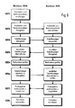
- FIG. 2 shows, using a flowchart for the computer network RV shown in FIG. 1 , how, according to the method according to the invention, the computers R1A, R1B and R1C in the computer node RK1 preferably determine and exchange useful and redundancy data before they send them via the communication channel KAN external to the node .
- the computer R1A is physically connected directly to the communication channel KAN external to the node. This means that the other two computers do not have an interface suitable for the communication channel KAN external to the node or at least have no drivers for operating an interface.
- the data exchange between the computer nodes RK1 and RK2 therefore always takes place via the computer R1A; the other computers cannot send any user data directly via the communication channel KAN outside the node.
- step S1 all three computers R1A determine R1B and RIC parallel and independent of each other user data.
- the necessary for this Input data can, for example, from another computer (node) come from a sensor or entered into the computer.
- the two computers determine in a step S2 R1B and R1C redundancy data for the user data determined by them.
- the computer According to the invention, R1A is not able to do this since it is directly above the node external Communication channel KAN can send data.
- step S3 the three computers exchange the user data determined by them and compare them them among themselves.
- the procedure for the redundancy data is similar in a step S4, with the difference that the exchange only between the two computers R1B and R1C takes place, since the computer R1A is not an option according to the invention has to determine correct redundancy data.
- Steps S3 and S4 can also if necessary be reversed.
- the comparison of the useful or redundancy data also includes one Majority decision, d. H. only data from a majority are accepted the computer in the computer node has been determined in agreement.
- the computer R1B transfers, in a step S6 the Computer R1C the redundancy data checked for compliance to the computer R1A.
- the user data and the redundancy data are then in one step S8 from the computer R1A via the node-external communication channel KAN to the sent to other computer nodes RK2.
- the computer R1A transmits in a step S7 before the transmission compares the adopted redundancy data with each other again. This measure does not serve to increase security, but rather availability. With negative After this comparison, the computer R1A asks the other two computers to to pass the redundancy data again. Then still no match Ascertained, the computer R1A assumes a defect in the internal node Communication channel KIK1 off and generates a diagnostic message. Subsequently The computer R1A then uses either that in step S5 or that in step S6 accepted redundancy data. Should it be incorrectly transferred redundancy data act, this is recognized by a receiving computer node.
- Fig. 3 it is shown how the received useful and redundancy data in the computer node RK2 are processed.
- the computer node RK2 There is also only one computer in the computer node RK2, here the computer R2A, directly with the communication channel external to the node KAN physically connected.
- the other two computers have R2B and R2C not the possibility directly via the communication channel external to the node KAN to send or receive user data.
- step E1 the computer R2A receives useful information sent by the computer R1A Redundancy data and transfers them to the other two in a step E2 Computer. Preferentially, but not necessarily, he himself does not have that Possibility of determining redundancy data so that the data passed on in step E2 Redundancy data certainly originate from the computer node RK1 or at most incorrectly received or self-generated from computer R2A User data have been determined.
- the useful and redundancy data transferred from the computer R2A are stored in one Step E3 evaluated by the computers R2B and R2C.
- the result of this evaluation consists either in the fact that the user data correspond to the redundancy data or that they don't correspond.
- compare the two Calculator R2B and R2C in a step E4 their results. Agree the results match, so they are from the two computers R2B and R2C in steps E5 and E6 transferred to the computer R2A.
- all process in a step E7 three computers receive or transmit user data. Further processing of user data by the computer R2A is preferably made dependent on it. whether the comparison results obtained from the other two computers match.
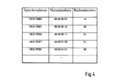
- Fig. 4 shows a simplified example such a table. Every possible user data byte is in this example assigned a combination of two redundancy bits. This assignment follows one mathematical law or can in principle also be arbitrary.
- a calculator that wants to determine redundancy data from user data, divides the user data into individual ones Bytes and searches for the associated redundancy bits for each byte in this table. All redundancy bits are then used to determine the redundancy data assembled or combined in some other way (totaling etc.). This The process is carried out both before sending and after receiving.
- the table is preferably stored in a data memory on each computer. Without this table, a computer cannot correctly extract the redundancy data Determine user data. If a computer should not have the option of using user data To determine redundancy data, according to the invention, this table is stored in the data memory "hidden". This is done by destroying the address at which the Table is saved. One way to do this is to use this address from the relevant computer itself or from another computer in the computer node is specifically overwritten with an incorrect address. Then it is arbitrary unlikely that the computer in question in one of the above Error scenarios randomly selects this address and finds the table.
- table pointer the start address of the table HEX F8B4, hereinafter referred to as "table pointer", with an incorrect value, approximately HEX 38C2. Only when the computer in question has redundancy data again should determine from user data, it receives the from the other computers correct table pointer.
- FIGS. 5 and 6 An exemplary embodiment is explained below with reference to FIGS. 5 and 6 which a computer node RKI comprising three computers R1A, R1B and R1C one two computers R2A and R2B comprising computer nodes useful and redundancy data sends.
- a computer node RKI comprising three computers R1A, R1B and R1C one two computers R2A and R2B comprising computer nodes useful and redundancy data sends.
- the determination of the redundancy data is carried out in step S2 using the table mentioned.
- the Calculator R1A which is permanently connected to the communication channel KAN external to the node is, the table is either not at all or only under one of it is not known address saved.
- a computer node consisting of only two computers occurs the difficulty that, for security reasons, redundancy data in principle to be checked by two different computers. If the receiving one Computer, in this case the computer R2A, is basically not able To compute redundancy data from user data, he can vice versa no redundancy data check. This problem is solved in that the receiving Computer R2A after having received the redundancy data to the other computer R2B passed, for a short period of time, even redundancy data to calculate.
- the procedure is preferably as outlined in FIG. 6.
- step EZ1 After receiving the useful data and redundancy data in a step EZ1 passes the computer R2A in a step EZ2 the received useful and redundancy data to the computer R2B.
- the computer R2A has only one at this time Table pointer pointing to an incorrect address. Then he passes in one Step EZ3 sends this "wrong" table pointer to the computer R2B. This checks whether the passed table pointer actually differs from the correct table pointer. This check ensures that the receiving computer R2A did not have the correct table pointer when it viewed the redundancy data passed on the computer R2B.
- step EZ4 the computer R2B now transfers the correct table pointer known to him to the computer R2A.
- the computer R2A destroys its table pointer, for example by overwriting with a different value, and passes the destroyed table pointer in a step EZ6 to the computer R2B. This compares the transferred table pointer with the correct table pointer known to him and verified thus that the computer R2A actually no longer has the correct table pointer disposes. As an alternative to this, the overwriting of the R2A in the computer stored table pointer also made directly by the computer R2B become. Another handover of the destroyed table pointer and subsequent Verification by the R2B computer, however, also makes sense with this variant.
- Step EZ7 Step EZ5 determined test results and compare them. Only if both exams are positive, the two computers are authorized to a step EZ8 to process the received user data.
- redundancy data from the user data using a redundancy data calculation process can be calculated in another way, that a computer that sends user data over the node-external communication channel Redundancy data determined.
- This exemplary embodiment is based on a computer architecture in which software modules are strictly separated by memory protection mechanisms.
- the processes that run within the middle and application level strictly separated. Messages between the processes are sent via so-called Message queues processed. This strictly directed and always verifiable communication also contributes to the independence of the processes.
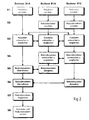
- FIG. 7 shows a schematic representation of a layer model of one of two Computers R1A and R1B existing computer node RK1.
- the hardware level sets the operating system level. This is functionally and logically divided into the Operating system kernel BSK, a communication system KS, which the above lying layers provides communication services, and a fault tolerance system FTS.
- the FTS fault tolerance system is responsible for the exchange and comparison of data within the computer node as well as for the node internal Handling errors.
- the middle level communicates with the underlying operating system level via defined, directed interfaces.
- the center plane comprises two completely separate input and output paths.
- a path is one or more processes that take place in protected address spaces and therefore cannot influence each other.
- a process is understood to be a code processed in a closed virtual memory area.
- Memory protection is essentially ensured by the memory management unit (MMU) of the processor unit, which maps the logical virtual memory addresses to the physical memory addresses.
- MMU memory management unit
- a component of the input paths is a redundancy data calculation process, which is used to calculate redundancy data from user data.
- the output paths do not both include such a redundancy data calculation process. Rather, it is provided according to the invention that only the output path of the computer R1B not connected to the node-external communication channel KAN has a redundancy data calculation process. The output path of the computer R1A connected to the node-external communication channel KAN has no redundancy data calculation process and can therefore not independently determine redundancy data.
- the output path of the computer R1A can also not on the redundancy data calculation process access in the output path of the computer R1B because it is located in a protected and therefore inaccessible address space. Such a Intervention is also due to the directional communication between the processes practically impossible with the help of message queues. For the same reasons the output path of the computer R1A is not one of the ones contained in the input paths Access redundancy data calculation processes.
- each computer creates a list of those in it existing processes and passes this list to the other computer. At Checking the passed lists must reveal that the redundancy data calculation process is not present in the output path of the computer R1A.
- redundancy data are usually calculated using a generator polynomial in single-channel secure transmission methods.
- CRC coding Cyclic Redundancy Code
- data is interpreted as polynomials in the GF (2) polynomial space.
- the GF (2) polynomial space has the property, among other things, that the coefficients can only assume the values 0 or 1.
- every polynomial in the GF (2) polynomial space can be interpreted as a sequence of zeros and ones.
- the length of a polynomial is equal to the length of this sequence and is [1.0] 8 in the above example. In this sense, there is also an equivalence between redundancy data and a redundancy polynomial.
- C (z) N (z) z k + R (z)
- the useful polynomial contains the actual useful data as well as additional data required for the transmission.
- the exponent k is the length of the redundancy polynomial R (z).
- the multiplication by z k clearly corresponds to a shift of the useful polynomial N (z) by k places to the left.
- the receiver also has the generator polynomial G (z). If the recipient receives a telegram polynomial C (z), which is not without remainder by the generator polynomial G (z) is divisible, he knows that a corruption has occurred. If the recipient can object to the falsification not determine based on this evaluation.
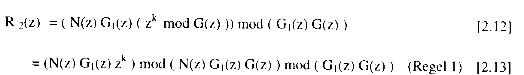
- this CRC method which is known per se, is now modified such that the interaction of two computers is always required in order to determine a correct redundancy polynomial R (z) from a useful polynomial N (z).
- both computers have different polynomial sets that cannot be easily derived from one another.
- the method according to the invention is based on the example of a two-computer system with two Calculator R1 and R2 explained.
- the computer R1 has direct access to one external communication channel, which is why he alone will not be able to should correctly determine a redundancy polynomial R (z).
- the polynomial sets of the two computers R1 and R2 are as follows Are defined:
- a 1 (z) G 2nd (z) (z k mod G (z))
- B 1 (z) G 2nd (z)
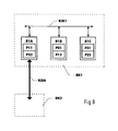
- FIG. 8 shows a modified representation of the computer node shown in FIG. 1 RK1.
- the polynomial sets P11 and P32 are in the computer R1A, and in the computer R1B the polynomial sets P21 and P12 and in the computer R1C the polynomial sets P31 and P22 filed.
- the polynomial sentence pairs ⁇ P11, P12 ⁇ , ⁇ P21, P22 ⁇ and ⁇ P31, P32 ⁇ work in each case together in the sense explained above.
- the calculator R1A can thus calculate a correct redundancy polynomial with the computer RIB the interaction of the polynomial sentences P11 and P12.
- the computers R1B and R2B via which the Communication between the computer nodes is no longer possible have to determine correct redundancy data.
- they have to the computer R1A and the node-external communication channel KAN If they are not defective themselves, R2A can be enabled again, redundancy data to investigate. How to do it in detail depends on how the computers determine redundancy data.
- the computers R1B and R2B pass immediately after the Switching process their correct table pointers to the computers R1A or R2A and then destroy the retained copy of the table pointer.
- the calculator R1A and R2A now have a correct table pointer themselves and are thus able to check that the computers R1B and R2B actually have theirs Have destroyed table pointers.
- the redundancy data according to variant 2 with the help of a redundancy data calculation process determined, so moves after a switchover from processor R1A to processor R1B, processor R1B is present in the output path Redundancy data calculation process to the computer R1A. After this The R1B computer no longer has the redundancy data calculation process, but the calculator R1A.
- the successful completion of this shift is preferably by comparing the process lists mentioned above verified.
- Switching to the replacement communication channel EKAN also takes place if one of the directly connected to the node-external communication channel KAN Computer is defective. However, this presupposes that the computer node, too to which the defective computer belongs, at least two more error-free computers includes. In this case, the error-free and not with the external node checks Substitute communication channel connected computer that that with the node external Computers connected to the primary communication channel no longer have a correct one Table pointer or via a redundancy data calculation process in the output path disposes.
Landscapes
- Engineering & Computer Science (AREA)
- Computer Networks & Wireless Communication (AREA)
- Signal Processing (AREA)
- Hardware Redundancy (AREA)
- Detection And Correction Of Errors (AREA)
- Error Detection And Correction (AREA)
- Communication Control (AREA)
Abstract
Description
- Fig. 1:
- Aufbau eines zur Ausführung des erfindungsgemäßen Verfahrens geeigneten Rechnerverbundes RV;
- Fig. 2:
- Flußdiagramms zur Erläuterung, wie bei dem in Fig. 1 dargestellten Rechnerverbund RV vor dem Senden von Nutz- und Redundanzdaten diese innerhalb eines Rechnerknotens ermittelt und ausgetauscht werden;
- Fig. 3:
- Flußdiagramms zur Erläuterung, wie bei dem in Fig. 1 dargestellten Rechnerverbund RV nach dem Empfang von Nutz- und Redundanzdaten diese innerhalb eines Rechnerknotens ausgewertet und ausgetauscht werden;
- Fig. 4:
- Tabelle zur Erläuterung einer Variante der Erfindung nach Anspruch 2;
- Fig. 5:
- Aufbau eines anderen zur Ausführung des erfindungsgemäßen Verfahrensgeeigneten Rechnerverbundes RV;
- Fig. 6:
- Flußdiagramms zur Erläuterung, wie bei dem in Fig. 5 dargestellten Rechnerverbund RV vor dem Senden von Nutz- und Redundanzdaten diese innerhalb eines Rechnerknotens ermittelt und ausgetauscht werden;
- Fig. 7:
- Schematische Darstellung der Architektur eines aus zwei Rechnern R1A und R1B bestehenden Rechnerknotens RK;
- Fig. 8:
- Abgewandelte Darstellung des in Fig. 1 dargestellten Rechnerknotens RK1 zur Erläuterung einer Variante der Erfindung nach Anspruch 5;
- Fig. 9:
- Aufbau eines weiteren zur Ausführung des erfindungsgemäßen Verfahrens geeigneten Rechnerverbundes RV, bei dem zusätzlich ein knotenexterner Ersatzkommunikationskanal EKAN vorgesehen ist.
- G (z):
- Generatorpolynom mit Grad k (nicht wählbar)
- G1(z):
- frei wählbares Polynom
- G2(z):
- frei wählbares Polynom mit G2(Z) ≠ G1(z)
- k:
- Länge des Redundanzpolynoms
A(z) mod ( B(z) C(z) ) mod B(z) = A(z) mod B(z) mod ( B(z) C(z) ) = A(z) mod B(z)
( A(z) B(z) ) mod ( A(z) C(z) ) = A(z) ( B(z) mod C(z) )


Claims (16)
- Verfahren zum sicheren einkanaligen Übertragen von Daten zwischen den Rechnerknoten (RK1, RK2) eines Rechnerverbundes (RV), insbesondere für den Einsatz in Eisenbahnsignalanlagen, bei dem
a) ein signaltechnisch sicher ausgeführter Rechnerknoten (RK1), der mindestens zwei parallel arbeitende, durch einen knoteninternen Kommunikationskanal untereinander verbundene Rechner (R1A, R1B, R1C) umfaßt, über einen knotenexternen Kommunikationskanal (KAN) an einen anderen derartigen Rechnerknoten (RK2) Nutzdaten und aus den Nutzdaten ermittelte und diese bei der Übertragung sichernde Redundanzdaten sendet,
dadurch gekennzeichnet,
b) daß verhindert wird, daß ein Rechner (R1A), der über den knotenexternen Kommunikationskanal Nutzdaten sendet, zu diesen Nutzdaten korrekte Redundanzdaten ermittelt. - Verfahren nach Anspruch 1, bei dema) die Redundanzdaten aus den Nutzdaten mit Hilfe einer Tabelle ermittelt werden, die in jedem Rechner in einem Datenspeicher unter festgelegten Adressen abgespeichert ist, und bei demb) sichergestellt wird, daß ein Rechner, der über den knotenexternen Kommunikationskanal Nutzdaten sendet, diese Adressen nicht kennt.
- Verfahren nach Anspruch 1, bei dema) die Redundanzdaten aus den Nutzdaten mit Hilfe eines Redundanzdatenberechnungsprozesses berechnet werden, und bei demb) verhindert wird, daß ein Rechner, der über den knotenexternen Kommunikationskanal Nutzdaten sendet, Zugriff auf einen Redundanzdatenberechnungsprozeß hat, mit dem zu diesen Nutzdaten korrekte Redundanzdaten berechenbar sind.
- Verfahren nach Anspruch 3, bei dem wenigstens ein Rechner, der nicht über den knotenexternen Kommunikationskanal Nutzdaten sendet, überprüft, ob der Rechner, der über den knotenexternen Kommunikationskanal Nutzdaten sendet, einen Redundanzdatenberechnungsprozeß hat, mit dem zu diesen Nutzdaten korrekte Redundanzdaten berechenbar sind.
- Verfahren nach Anspruch 1, bei dem die Redundanzdaten durch Zusammenwirken von zwei unterschiedlichen, auf verschiedenen Rechnern (R1A, R1B, R1C in Fig. 8) abgelegten Polynomsätzen (P11, P12; P21, P22; P31, P32) ermittelt werden.
- Verfahren nach einem der vorhergehenden Ansprüche, bei dem ferner verhindert wird, daß ein Rechner, der über den knotenexternen Kommunikationskanal (KAN) Nutzdaten empfängt, zu diesen Nutzdaten korrekte Redundanzdaten ermittelt.
- Verfahren nach einem der vorhergehenden Ansprüche, bei dem in jedem Rechnerknoten genau ein Rechner mit dem knotenexternen Kommunikationskanal physikalisch verbunden ist.
- Verfahren nach Anspruch 6, bei dem, wenn der knotenexterne Kommunikationskanal (KAN) defekt ist, die Übertragung zwischen dem einen (RK1) und dem anderen (RK2) Rechnerknoten über einen zusätzlichen knotenexternen Ersatzkommunikationskanal (EKAN) erfolgt, der nicht mit den gleichen Rechnern physikalisch verbunden ist wie der knotenexterne Kommunikationskanal (KAN).
- Rechnerverbund (RV), insbesondere für den Einsatz in Eisenbahnsignalanlagen, mit:dadurch gekennzeichnet,a) zwei signaltechnisch sicher ausgeführten Rechnerknoten (RK1, RK2), die jeweils mindestens zwei parallel Nutzdaten ermittelnde, über einen knoteninternen Kommunikationskanal (KIK1, KIK2) untereinander verbundene Rechner (R1A, R1B, R1C; R2A, R2B, R2C) umfassen, und mitb) einem knotenexternen Kommunikationskanal (KAN) zwischen den beiden Rechnerknoten zur Übertragung der Nutzdaten und von aus den Nutzdaten ermittelten und diese bei der Übertragung sichernden Redundanzdaten,
daß in jedem Rechnerknoten Mittel vorhanden sind zum Verhindern, daß ein Rechner, der über den knotenexternen Kommunikationskanal (KAN) Nutzdaten sendet, zu diesen Nutzdaten korrekte Redundanzdaten ermittelt. - Rechnerverbund nach Anspruch 9, bei dema) die Redundanzdaten aus den Nutzdaten mit Hilfe einer Tabelle ermittelbar sind, die in jedem Rechner in einem Datenspeicher unter festgelegten Adressen abgespeichert ist, und bei demb) die Mittel Programmittel sind, die sicherstellen, daß ein Rechner, der über den knotenexternen Kommunikationskanal Nutzdaten sendet, diese Adressen nicht kennt.
- Rechnerverbund nach Anspruch 9, bei dema) die Redundanzdaten aus den Nutzdaten mit Hilfe eines Redundanzdatenberechnungsprozesses berechenbar sind, und bei demb) die Mittel Programmittel sind, die verhindern, daß ein Rechner, der über den knotenexternen Kommunikationskanal Nutzdaten sendet, Zugriff auf einen Redundanzdatenberechnungsprozeß hat, mit dem zu diesen Nutzdaten korrekte Redundanzdaten berechenbar sind.
- Rechnerverbund nach Anspruch 11, bei dem wenigstens ein Rechner, der nicht über den knotenexternen Kommunikationskanal Nutzdaten sendet, Prüfmittel hat zum Überprüfen, ob der Rechner, der über den knotenexternen Kommunikationskanal Nutzdaten sendet, einen Redundanzdatenberechnungsprozeß hat, mit dem zu diesen Nutzdaten korrekte Redundanzdaten berechenbar sind.
- Rechnerverbund nach Anspruch 9, bei dem zweite Mittel vorhanden sind, die verhindern, daß ein Rechner, der über den knotenexternen Kommunikationskanal (KAN) Nutzdaten empfängt, zu diesen Nutzdaten korrekte Redundanzdaten ermittelt.
- Rechnerverbund nach einem der Ansprüche 9 bis 13, bei dem in jedem Rechnerknoten genau ein Rechner mit dem knotenexternen Kommunikationskanal physikalisch verbunden ist.
- Rechnerverbund nach Anspruch 14, bei dem zwischen den beiden Rechnerknoten ein knotenexterner Ersatzkommunikationskanal (EKAN) vorgesehen ist, der nicht mit den gleichen Rechnern physikalisch verbunden ist wie der knotenexterne Kommunikationskanal KAN.
- Signaltechnisch sicher ausgeführter Rechnerknoten (RK1, RK2) , insbesondere für den Einsatz in Eisenbahnsignalanlagen, mit:dadurch gekennzeichnet,a) mindestens zwei parallel Nutzdaten ermittelnden, über einen knoteninternen Kommunikationskanal (KIK1, KIK2) untereinander verbundenen Rechnern (R1A, R1B, R1C; R2A, R2B, R2C), und mitb) wenigstens einer Übertragungsschnittstelle an einen weiteren Rechnerknoten zur Übertragung der Nutzdaten und von aus den Nutzdaten ermittelten und diese bei der Übertragung sichernden Redundanzdaten,
daß Mittel vorhanden sind zum Verhindern, daß ein Rechner, der über die Ausgabeschnittstelle Nutzdaten sendet, zu diesen Nutzdaten korrekte Redundanzdaten ermittelt.
Applications Claiming Priority (2)
| Application Number | Priority Date | Filing Date | Title |
|---|---|---|---|
| DE19833867A DE19833867C5 (de) | 1998-07-28 | 1998-07-28 | Verfahren zur sicheren einkanaligen Übertragung von Daten zwischen den Rechnerknoten eines Rechnerverbundes sowie Rechnerverbund und Rechnerknoten |
| DE19833867 | 1998-07-28 |
Publications (2)
| Publication Number | Publication Date |
|---|---|
| EP0977395A1 true EP0977395A1 (de) | 2000-02-02 |
| EP0977395B1 EP0977395B1 (de) | 2006-04-05 |
Family
ID=7875530
Family Applications (1)
| Application Number | Title | Priority Date | Filing Date |
|---|---|---|---|
| EP99440213A Expired - Lifetime EP0977395B1 (de) | 1998-07-28 | 1999-07-28 | Verfahren zur sicheren einkanaligen Übertragung von Daten zwischen den Rechnerknoten eines Rechnerverbundes sowie Rechnerverbund und Rechnerknoten |
Country Status (3)
| Country | Link |
|---|---|
| EP (1) | EP0977395B1 (de) |
| AT (1) | ATE322777T1 (de) |
| DE (2) | DE19833867C5 (de) |
Cited By (3)
| Publication number | Priority date | Publication date | Assignee | Title |
|---|---|---|---|---|
| EP2884392A1 (de) * | 2013-12-13 | 2015-06-17 | Thales | Fehlertolerante Rahmenarchitektur mit dreifacher Software-Redundanz |
| WO2015150070A1 (de) * | 2014-03-31 | 2015-10-08 | Siemens Aktiengesellschaft | Ersatz-ressource für einen defekten rechnerkanal eines schienenfahrzeugs |
| WO2026061645A1 (de) * | 2024-09-19 | 2026-03-26 | Bayerische Motoren Werke Aktiengesellschaft | Verfahren zum absichern einer übertragung von nutzdaten sowie dafür eingerichtetes sendergerät und kraftfahrzeug |
Families Citing this family (6)
| Publication number | Priority date | Publication date | Assignee | Title |
|---|---|---|---|---|
| DE10011887B4 (de) * | 2000-03-07 | 2004-09-02 | Siemens Ag | Verfahren zur signaltechnisch sicheren Übermittlung von Daten zwischen signaltechnisch sicheren Rechnern sowie Einrichtung hierzu |
| DE10345633A1 (de) * | 2003-09-29 | 2005-05-12 | Siemens Ag | Safetymodul zur Verarbeitung sicherheitsrelevanter Bedienungen insbesondere von Stop- und Zustimmungstastern eines mobilen Bedien- und Beobachtungsgeräts in einem HMI System |
| DE502004006409D1 (de) | 2004-05-10 | 2008-04-17 | Siemens Ag | Verfahren zur einkanaligen Übertragung von redundant vorliegenden Daten |
| EP1710940A1 (de) | 2005-04-06 | 2006-10-11 | Siemens Aktiengesellschaft | Erkennung von Fehlern bei der Übermittlung von Daten |
| DE102007032805A1 (de) * | 2007-07-10 | 2009-01-15 | Siemens Ag | Verfahren und Systemarchitektur zur sicheren einkanaligen Kommunikation zum Steuern eines sicherheitskritischen Bahnbetriebsprozesses |
| FR2992083B1 (fr) | 2012-06-19 | 2014-07-04 | Alstom Transport Sa | Calculateur, ensemble de communication comportant un tel calculateur, systeme de gestion ferroviaire comportant un tel ensemble, et procede de fiabilisation de donnees dans un calculateur |
Citations (2)
| Publication number | Priority date | Publication date | Assignee | Title |
|---|---|---|---|---|
| DE4315710A1 (de) * | 1993-05-11 | 1993-10-07 | Siemens Ag | Nachrichtenübertragungsverfahren |
| EP0720337A2 (de) * | 1994-12-15 | 1996-07-03 | ABBPATENT GmbH | Verfahren zur hochzuverlässigen und konsistenten Nachrichtenübertragung |
Family Cites Families (3)
| Publication number | Priority date | Publication date | Assignee | Title |
|---|---|---|---|---|
| DE3742118A1 (de) * | 1987-12-11 | 1989-06-22 | Siemens Ag | Signaltechnisch sichere datenuebertragungseinrichtung |
| DE19532640C2 (de) * | 1995-08-23 | 2000-11-30 | Siemens Ag | Einrichtung zur einkanaligen Übertragung von aus zwei Datenquellen stammenden Daten |
| DE19532639C2 (de) * | 1995-08-23 | 2000-11-30 | Siemens Ag | Einrichtung zur einkanaligen Übertragung von aus zwei Datenquellen stammenden Daten |
-
1998
- 1998-07-28 DE DE19833867A patent/DE19833867C5/de not_active Expired - Lifetime
-
1999
- 1999-07-28 DE DE59913296T patent/DE59913296D1/de not_active Expired - Lifetime
- 1999-07-28 AT AT99440213T patent/ATE322777T1/de not_active IP Right Cessation
- 1999-07-28 EP EP99440213A patent/EP0977395B1/de not_active Expired - Lifetime
Patent Citations (2)
| Publication number | Priority date | Publication date | Assignee | Title |
|---|---|---|---|---|
| DE4315710A1 (de) * | 1993-05-11 | 1993-10-07 | Siemens Ag | Nachrichtenübertragungsverfahren |
| EP0720337A2 (de) * | 1994-12-15 | 1996-07-03 | ABBPATENT GmbH | Verfahren zur hochzuverlässigen und konsistenten Nachrichtenübertragung |
Cited By (5)
| Publication number | Priority date | Publication date | Assignee | Title |
|---|---|---|---|---|
| EP2884392A1 (de) * | 2013-12-13 | 2015-06-17 | Thales | Fehlertolerante Rahmenarchitektur mit dreifacher Software-Redundanz |
| WO2015086488A1 (en) | 2013-12-13 | 2015-06-18 | Thales | Triple software redundancy fault tolerant framework architecture |
| US10095601B2 (en) | 2013-12-13 | 2018-10-09 | Thales | Triple software redundancy fault tolerant framework architecture |
| WO2015150070A1 (de) * | 2014-03-31 | 2015-10-08 | Siemens Aktiengesellschaft | Ersatz-ressource für einen defekten rechnerkanal eines schienenfahrzeugs |
| WO2026061645A1 (de) * | 2024-09-19 | 2026-03-26 | Bayerische Motoren Werke Aktiengesellschaft | Verfahren zum absichern einer übertragung von nutzdaten sowie dafür eingerichtetes sendergerät und kraftfahrzeug |
Also Published As
| Publication number | Publication date |
|---|---|
| ATE322777T1 (de) | 2006-04-15 |
| DE19833867C2 (de) | 2000-07-06 |
| EP0977395B1 (de) | 2006-04-05 |
| DE19833867C5 (de) | 2006-10-12 |
| DE19833867A1 (de) | 2000-02-03 |
| DE59913296D1 (de) | 2006-05-18 |
Similar Documents
| Publication | Publication Date | Title |
|---|---|---|
| EP3177973B1 (de) | Verfahren zum betreiben einer sicherheitssteuerung und automatisierungsnetzwerk mit einer solchen sicherheitssteuerung | |
| EP3501154A1 (de) | Bereitstellen einer gesicherten kommunikation innerhalb eines echtzeitfähigen kommunikationsnetzwerkes | |
| EP1802019B1 (de) | Erkennung von Fehlern bei der Übermittlung von Daten | |
| DE112006001165B4 (de) | Kommunikationsvorrichtung und Schalteinrichtung | |
| EP1631014B1 (de) | Verfahren und Vorrichtung zur Busankopplung sicherheitsrelevanter Prozesse | |
| EP1811722A2 (de) | Verfahren und Vorrichtung zur Umwandlung mehrkanalig vorliegender Nachrichten in eine einkanalige sichere Nachricht | |
| DE19833867C2 (de) | Verfahren zur sicheren einkanaligen Übertragung von Daten zwischen den Rechnerknoten eines Rechnerverbundes sowie Rechnerverbund und Rechnerknoten | |
| EP3020162B1 (de) | Semantische deduplikation | |
| WO2007093427A1 (de) | Verfahren und vorrichtung zur busankopplung sicherheitsrelevanter prozesse | |
| EP2839601B1 (de) | Feldbus-datenübertragung | |
| EP1596517B1 (de) | Verfahren zur einkanaligen Übertragung von redundant vorliegenden Daten | |
| EP1686732A1 (de) | Verfahren und System zur Übertragung von Telegrammen | |
| DE102021127310B4 (de) | System und Verfahren zur Datenübertragung | |
| WO2017186457A1 (de) | Verfahren zur wegredundanzbewertung in einem backbone-netzwerk | |
| CH705315A1 (de) | Tabellengesteuertes System. | |
| DE102022211587B4 (de) | Sicherer Betrieb von redundanten, einfehlertoleranten Steuergeräten im Fahrzeug mit signierten Signalen | |
| DE102013204891B4 (de) | Verfahren zur Rekonstruktion von Messdaten | |
| DE102013204371A1 (de) | Verfahren und Bussystem zum protokollunabhängigen Übertragen von Standarddatenpaketen mit Sicherheitsdaten | |
| DE102004018858A1 (de) | Verfahren und Steuerungssystem zum Erkennen eines Fehlers bei einer Verarbeitung von Daten in einem Verarbeitungssystem | |
| WO2021058561A1 (de) | Verfahren zum betreiben eines kommunikationsnetzwerks, kommunikationsnetzwerk und teilnehmer für ein kommunikationsnetzwerk | |
| WO2021151612A1 (de) | Verfahren zur überprüfung einer signalverbindung | |
| DE10148323A1 (de) | Verfahren zum Funktionstest von Steuergeräten und Programmen | |
| WO2021018697A1 (de) | Übertragungsvorrichtung zum übertragen von daten | |
| DE102020111450A1 (de) | Erkennen von Fehlern in einem Computernetzwerk | |
| DE102005059021A1 (de) | Eingebettetes System und Verfahren zum Betreiben eines eingebetteten Systems mit verbesserter Kennzeichnung von fehlerhaften ausgetauschten Signalen |
Legal Events
| Date | Code | Title | Description |
|---|---|---|---|
| PUAI | Public reference made under article 153(3) epc to a published international application that has entered the european phase |
Free format text: ORIGINAL CODE: 0009012 |
|
| AK | Designated contracting states |
Kind code of ref document: A1 Designated state(s): AT BE CH CY DE DK ES FI FR GB GR IE IT LI LU MC NL PT SE |
|
| AX | Request for extension of the european patent |
Free format text: AL;LT;LV;MK;RO;SI |
|
| AKX | Designation fees paid |
Free format text: AT BE CH CY DE DK ES FI FR GB GR IE IT LI LU MC NL PT SE |
|
| 17P | Request for examination filed |
Effective date: 20000314 |
|
| GRAP | Despatch of communication of intention to grant a patent |
Free format text: ORIGINAL CODE: EPIDOSNIGR1 |
|
| GRAS | Grant fee paid |
Free format text: ORIGINAL CODE: EPIDOSNIGR3 |
|
| GRAA | (expected) grant |
Free format text: ORIGINAL CODE: 0009210 |
|
| AK | Designated contracting states |
Kind code of ref document: B1 Designated state(s): AT BE CH CY DE DK ES FI FR GB GR IE IT LI LU MC NL PT SE |
|
| PG25 | Lapsed in a contracting state [announced via postgrant information from national office to epo] |
Ref country code: NL Free format text: LAPSE BECAUSE OF FAILURE TO SUBMIT A TRANSLATION OF THE DESCRIPTION OR TO PAY THE FEE WITHIN THE PRESCRIBED TIME-LIMIT Effective date: 20060405 Ref country code: IE Free format text: LAPSE BECAUSE OF FAILURE TO SUBMIT A TRANSLATION OF THE DESCRIPTION OR TO PAY THE FEE WITHIN THE PRESCRIBED TIME-LIMIT Effective date: 20060405 Ref country code: FI Free format text: LAPSE BECAUSE OF FAILURE TO SUBMIT A TRANSLATION OF THE DESCRIPTION OR TO PAY THE FEE WITHIN THE PRESCRIBED TIME-LIMIT Effective date: 20060405 |
|
| REG | Reference to a national code |
Ref country code: GB Ref legal event code: FG4D Free format text: NOT ENGLISH |
|
| REG | Reference to a national code |
Ref country code: CH Ref legal event code: EP |
|
| GBT | Gb: translation of ep patent filed (gb section 77(6)(a)/1977) |
Effective date: 20060405 |
|
| REG | Reference to a national code |
Ref country code: IE Ref legal event code: FG4D Free format text: LANGUAGE OF EP DOCUMENT: GERMAN |
|
| REF | Corresponds to: |
Ref document number: 59913296 Country of ref document: DE Date of ref document: 20060518 Kind code of ref document: P |
|
| PG25 | Lapsed in a contracting state [announced via postgrant information from national office to epo] |
Ref country code: SE Free format text: LAPSE BECAUSE OF FAILURE TO SUBMIT A TRANSLATION OF THE DESCRIPTION OR TO PAY THE FEE WITHIN THE PRESCRIBED TIME-LIMIT Effective date: 20060705 Ref country code: DK Free format text: LAPSE BECAUSE OF FAILURE TO SUBMIT A TRANSLATION OF THE DESCRIPTION OR TO PAY THE FEE WITHIN THE PRESCRIBED TIME-LIMIT Effective date: 20060705 |
|
| PG25 | Lapsed in a contracting state [announced via postgrant information from national office to epo] |
Ref country code: ES Free format text: LAPSE BECAUSE OF FAILURE TO SUBMIT A TRANSLATION OF THE DESCRIPTION OR TO PAY THE FEE WITHIN THE PRESCRIBED TIME-LIMIT Effective date: 20060716 |
|
| PG25 | Lapsed in a contracting state [announced via postgrant information from national office to epo] |
Ref country code: MC Free format text: LAPSE BECAUSE OF NON-PAYMENT OF DUE FEES Effective date: 20060731 Ref country code: LI Free format text: LAPSE BECAUSE OF NON-PAYMENT OF DUE FEES Effective date: 20060731 Ref country code: CH Free format text: LAPSE BECAUSE OF NON-PAYMENT OF DUE FEES Effective date: 20060731 Ref country code: BE Free format text: LAPSE BECAUSE OF NON-PAYMENT OF DUE FEES Effective date: 20060731 |
|
| PG25 | Lapsed in a contracting state [announced via postgrant information from national office to epo] |
Ref country code: PT Free format text: LAPSE BECAUSE OF FAILURE TO SUBMIT A TRANSLATION OF THE DESCRIPTION OR TO PAY THE FEE WITHIN THE PRESCRIBED TIME-LIMIT Effective date: 20060905 |
|
| ET | Fr: translation filed | ||
| NLV1 | Nl: lapsed or annulled due to failure to fulfill the requirements of art. 29p and 29m of the patents act | ||
| REG | Reference to a national code |
Ref country code: IE Ref legal event code: FD4D |
|
| REG | Reference to a national code |
Ref country code: CH Ref legal event code: PL |
|
| PLBE | No opposition filed within time limit |
Free format text: ORIGINAL CODE: 0009261 |
|
| STAA | Information on the status of an ep patent application or granted ep patent |
Free format text: STATUS: NO OPPOSITION FILED WITHIN TIME LIMIT |
|
| 26N | No opposition filed |
Effective date: 20070108 |
|
| PG25 | Lapsed in a contracting state [announced via postgrant information from national office to epo] |
Ref country code: AT Free format text: LAPSE BECAUSE OF NON-PAYMENT OF DUE FEES Effective date: 20060728 |
|
| BERE | Be: lapsed |
Owner name: ALCATEL Effective date: 20060731 |
|
| PG25 | Lapsed in a contracting state [announced via postgrant information from national office to epo] |
Ref country code: GR Free format text: LAPSE BECAUSE OF FAILURE TO SUBMIT A TRANSLATION OF THE DESCRIPTION OR TO PAY THE FEE WITHIN THE PRESCRIBED TIME-LIMIT Effective date: 20060706 |
|
| PG25 | Lapsed in a contracting state [announced via postgrant information from national office to epo] |
Ref country code: LU Free format text: LAPSE BECAUSE OF NON-PAYMENT OF DUE FEES Effective date: 20060728 |
|
| PG25 | Lapsed in a contracting state [announced via postgrant information from national office to epo] |
Ref country code: CY Free format text: LAPSE BECAUSE OF FAILURE TO SUBMIT A TRANSLATION OF THE DESCRIPTION OR TO PAY THE FEE WITHIN THE PRESCRIBED TIME-LIMIT Effective date: 20060405 |
|
| REG | Reference to a national code |
Ref country code: FR Ref legal event code: PLFP Year of fee payment: 18 |
|
| REG | Reference to a national code |
Ref country code: FR Ref legal event code: PLFP Year of fee payment: 19 |
|
| REG | Reference to a national code |
Ref country code: FR Ref legal event code: PLFP Year of fee payment: 20 |
|
| PGFP | Annual fee paid to national office [announced via postgrant information from national office to epo] |
Ref country code: IT Payment date: 20180713 Year of fee payment: 20 Ref country code: DE Payment date: 20180717 Year of fee payment: 20 Ref country code: FR Payment date: 20180712 Year of fee payment: 20 |
|
| PGFP | Annual fee paid to national office [announced via postgrant information from national office to epo] |
Ref country code: GB Payment date: 20180717 Year of fee payment: 20 |
|
| REG | Reference to a national code |
Ref country code: DE Ref legal event code: R071 Ref document number: 59913296 Country of ref document: DE |
|
| REG | Reference to a national code |
Ref country code: GB Ref legal event code: PE20 Expiry date: 20190727 |
|
| PG25 | Lapsed in a contracting state [announced via postgrant information from national office to epo] |
Ref country code: GB Free format text: LAPSE BECAUSE OF EXPIRATION OF PROTECTION Effective date: 20190727 |