EP0979900A1 - Dichtwandkammersystem - Google Patents
Dichtwandkammersystem Download PDFInfo
- Publication number
- EP0979900A1 EP0979900A1 EP99115564A EP99115564A EP0979900A1 EP 0979900 A1 EP0979900 A1 EP 0979900A1 EP 99115564 A EP99115564 A EP 99115564A EP 99115564 A EP99115564 A EP 99115564A EP 0979900 A1 EP0979900 A1 EP 0979900A1
- Authority
- EP
- European Patent Office
- Prior art keywords
- hydraulic valve
- producing
- sealing
- chambers
- filter
- Prior art date
- Legal status (The legal status is an assumption and is not a legal conclusion. Google has not performed a legal analysis and makes no representation as to the accuracy of the status listed.)
- Granted
Links
- 238000007789 sealing Methods 0.000 claims abstract description 41
- 238000004519 manufacturing process Methods 0.000 claims description 27
- XLYOFNOQVPJJNP-UHFFFAOYSA-N water Substances O XLYOFNOQVPJJNP-UHFFFAOYSA-N 0.000 claims description 23
- 238000009434 installation Methods 0.000 claims description 9
- 239000000463 material Substances 0.000 claims description 9
- 238000000034 method Methods 0.000 claims description 5
- 239000004698 Polyethylene Substances 0.000 claims 1
- 239000007788 liquid Substances 0.000 claims 1
- -1 polyethylene Polymers 0.000 claims 1
- 229920000573 polyethylene Polymers 0.000 claims 1
- 229910001220 stainless steel Inorganic materials 0.000 claims 1
- 239000010935 stainless steel Substances 0.000 claims 1
- ZZUFCTLCJUWOSV-UHFFFAOYSA-N furosemide Chemical compound C1=C(Cl)C(S(=O)(=O)N)=CC(C(O)=O)=C1NCC1=CC=CO1 ZZUFCTLCJUWOSV-UHFFFAOYSA-N 0.000 description 6
- 238000012360 testing method Methods 0.000 description 4
- 210000001742 aqueous humor Anatomy 0.000 description 3
- 230000035699 permeability Effects 0.000 description 3
- 244000089486 Phragmites australis subsp australis Species 0.000 description 2
- 238000011109 contamination Methods 0.000 description 2
- 238000013461 design Methods 0.000 description 2
- 238000005553 drilling Methods 0.000 description 2
- 239000003673 groundwater Substances 0.000 description 2
- 230000007246 mechanism Effects 0.000 description 2
- 238000012544 monitoring process Methods 0.000 description 2
- 238000004062 sedimentation Methods 0.000 description 2
- 239000002689 soil Substances 0.000 description 2
- XEEYBQQBJWHFJM-UHFFFAOYSA-N Iron Chemical compound [Fe] XEEYBQQBJWHFJM-UHFFFAOYSA-N 0.000 description 1
- 238000004891 communication Methods 0.000 description 1
- 238000010276 construction Methods 0.000 description 1
- 239000000356 contaminant Substances 0.000 description 1
- 238000011161 development Methods 0.000 description 1
- 230000018109 developmental process Effects 0.000 description 1
- 230000000694 effects Effects 0.000 description 1
- 238000005516 engineering process Methods 0.000 description 1
- 230000003628 erosive effect Effects 0.000 description 1
- 230000004807 localization Effects 0.000 description 1
- 230000007257 malfunction Effects 0.000 description 1
- 230000000737 periodic effect Effects 0.000 description 1
- 239000003566 sealing material Substances 0.000 description 1
- 238000000926 separation method Methods 0.000 description 1
- 238000004078 waterproofing Methods 0.000 description 1
Images


Classifications
-
- E—FIXED CONSTRUCTIONS
- E02—HYDRAULIC ENGINEERING; FOUNDATIONS; SOIL SHIFTING
- E02D—FOUNDATIONS; EXCAVATIONS; EMBANKMENTS; UNDERGROUND OR UNDERWATER STRUCTURES
- E02D19/00—Keeping dry foundation sites or other areas in the ground
- E02D19/06—Restraining of underground water
- E02D19/12—Restraining of underground water by damming or interrupting the passage of underground water
-
- B—PERFORMING OPERATIONS; TRANSPORTING
- B09—DISPOSAL OF SOLID WASTE; RECLAMATION OF CONTAMINATED SOIL
- B09C—RECLAMATION OF CONTAMINATED SOIL
- B09C1/00—Reclamation of contaminated soil
- B09C1/002—Reclamation of contaminated soil involving in-situ ground water treatment
-
- E—FIXED CONSTRUCTIONS
- E02—HYDRAULIC ENGINEERING; FOUNDATIONS; SOIL SHIFTING
- E02D—FOUNDATIONS; EXCAVATIONS; EMBANKMENTS; UNDERGROUND OR UNDERWATER STRUCTURES
- E02D19/00—Keeping dry foundation sites or other areas in the ground
- E02D19/06—Restraining of underground water
- E02D19/12—Restraining of underground water by damming or interrupting the passage of underground water
- E02D19/18—Restraining of underground water by damming or interrupting the passage of underground water by making use of sealing aprons, e.g. diaphragms made from bituminous or clay material
Definitions
- the invention relates to a method for producing a hydraulic connection of diaphragm wall chambers Sealing wall chamber system consisting of parallel to each other trending sealing walls and transverse bulkheads, which are at intervals are arranged between the sealing walls.
- sealing elements can in be executed in various forms, for example as overlapped bored pile wall, as a diaphragm wall in single-phase and Two-phase process, as a narrow wall, as High pressure erosion wall and as HDI wall, which in one incorporate a waterproof layer or for the purpose of a horizontal waterproofing with artificial waterproof Soles such as HDI soles or underwater concrete soles are provided.
- the system tightness of an enclosure The two-shell chamber system has to be able to check proven. Two sealing elements run in parallel created by transverse bulkheads in individual chambers be divided.
- Drainage measures such as lowering the water level within the containment and regulation of the Aqueous humor to a level between outside and Internal water level creates a hydraulic gradient which prevents contaminated water from escaping from the enclosed area prevented.
- the individual chambers of a chamber system are usually as self-sufficient systems and without any connection with neighboring chambers built.
- To operate the Chamber systems can optimize several neighboring ones Chambers with the help of so-called chamber connection structures such as elliptical concrete manholes, which is a hydraulic connection of the chambers in normal operation enable each other and during a chamber test are separable.
- the individual chambers can also be used with a Filter pipe ring line must be equipped so that also a hydraulic connection between the chambers among themselves is made possible. In both systems Regular operation of the chamber system of free water flow guaranteed by all chambers.
- the systems with chamber connection structures or one Filter pipe ring line are in the area of the transverse bulkhead Provide shut-off devices, with the help of which the individual Chambers partitioned hydraulically for a chamber test can be.
- the shut-off devices are for one Chamber examination closed.
- Each chamber is also with one Water management system consisting of a pump and a electronically controlled control and regulation system fitted. This system continuously measures that Water level in the chambers and pumps when the Pure water inside the chamber or takes it out this water when the aqueous water level is above a Setpoint increases.
- the chamber geometry to be executed includes and the chamber length, in particular, is always a compromise between the specification, the shortest possible chambers and thus one manageable control area for localization to suggest any leaks that may occur.
- the invention is based on the objects, a simple, reliable and inexpensive method for hydraulic Connection of all chambers of a chamber system to specify the the creation of complex chamber connection structures or the installation of lockable filter pipe ring lines superfluous and also the effort for the Control and control of the aqueous humor level reduced become. In particular, it aims at elaborate electronic Monitoring and control mechanisms are dispensed with.
- the invention solves the problem with the features of Claim 1. According to the invention it has been recognized that it is possible to overcome the disadvantages of the prior art avoid by first drilling a hole in the transverse bulkhead sunk and then installed a hydraulic valve in the hole becomes.
- the invention now has several advantages. So lets a hydraulic connection in a simple way between the individual chambers. If necessary this hydraulic connection by closing the Hydro valve are interrupted. So on the one hand in Regular operation a common and therefore simplified Control of the chamber system take place, on the other hand, however separation into individual chambers is also possible without any problems.
- the Use of mechanical shut-off devices to seal off the individual diaphragm wall chambers are omitted.
- the hydraulic control valve is positioned in the chamber in such a way that with an inner wall denser than the outer wall Hydro control valve is placed in the inner wall, whereas in the case of an outer wall which is denser than the inner wall Hydro control valve is placed in the outer wall.
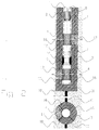
- FIG. 3 shows a further advantageous design of the Hydro valve 1 according to the invention shown.
- the hydro valve 1 is in this case a so-called hydraulic control valve 15 designed.
- Bore 10 made in the one with four chamber wings 3rd equipped pipe 2 with superimposed, spatially separate filter sections 4 and intermediate full pipe 12, in which the float valve 13 is installed becomes.
- the effect of the float valve 13 is based on the Principle of buoyancy.
- the float valve 13 remains as long closed and seals against the seal 14 of the Valve seat 9 from as long as the sum of its own weight plus the pressure from above Float valve 13 is greater than the pressure force plus dynamic flow force from below.
- the invention in both vertical as well as in an oblique hole can. Oblique holes are used when the Accessibility of the sealing element from above no longer is guaranteed.
- the sealing element to be treated (Bulkhead 11, inner or outer wall) in a certain Pierce depth and here the hydraulic valve 1 or that Hydraulic control valve 15 installed.
- the invention can continue used to be formerly waterproof Construction pit enclosures after the requirement ceases to exist To make water flow through again (e.g. at Wall-sole systems with, for example, a deep one Nozzle jet soles).
- the filter chambers 17 filled with a reactive material e.g.
Landscapes
- Engineering & Computer Science (AREA)
- Life Sciences & Earth Sciences (AREA)
- Environmental & Geological Engineering (AREA)
- Hydrology & Water Resources (AREA)
- General Engineering & Computer Science (AREA)
- Mining & Mineral Resources (AREA)
- Paleontology (AREA)
- Civil Engineering (AREA)
- General Life Sciences & Earth Sciences (AREA)
- Structural Engineering (AREA)
- Soil Sciences (AREA)
- Water Supply & Treatment (AREA)
- Details Of Valves (AREA)
- Electrical Discharge Machining, Electrochemical Machining, And Combined Machining (AREA)
- Physical Deposition Of Substances That Are Components Of Semiconductor Devices (AREA)
- Glass Compositions (AREA)
- Prostheses (AREA)
- Fluid-Pressure Circuits (AREA)
- Valve-Gear Or Valve Arrangements (AREA)
Abstract
Description
- 1
- Hydroventil
- 2
- Rohr
- 3
- Kammerflügel
- 4
- Filterstrecke
- 5
- Packer
- 6
- Gestänge
- 7
- Verschlußkonus
- 8
- Zugmittel
- 9
- Ventilsitz
- 10
- Bohrung
- 11
- Querschott
- 12
- Vollrohr
- 13
- Schwimmerventil
- 14
- Dichtung
- 15
- Hydroregelventil
- 16
- Dichtkammer
- 17
- Filterkammer
- 18
- Baugrund
Claims (20)
- Verfahren zur Herstellung einer hydraulischen Verbindung von Dichtwandkammern eines Dichtwandkammersystems bestehend aus parallel zueinander verlaufenden Dichtwänden und Querschotts (11), die in Abständen zwischen den Dichtwänden angeordnet sind,
dadurch gekennzeichnet, daß
zunächst eine Bohrung (10) in das Querschott (11) abgeteuft wird und danach ein Hydroventil (1) in die Bohrung (10) eingebaut wird. - Verfahren zur Steuerung des Wasserspiegels in einem Dichtwandkammersystem bestehend aus parallel zueinander verlaufenden Dichtwänden und Querschotts (11), die in Abständen zwischen den Dichtwänden angeordnet sind,
dadurch gekennzeichnet, daß
zunächst eine Bohrung (10) in eine der Dichtwände des Kammersystems abgeteuft wird und danach ein Hydroregelventil (15) in die Bohrung (10) eingebaut wird. - Verfahren zur Herstellung eines Hydroventils (1) nach einem der Ansprüche 1 oder 2, dadurch gekennzeichnet, daß eine Bohrung (10) hergestellt wird, in die ein mit angeschweißten Kammerflügeln (3) ausgestattetes Rohr (2) eingebaut wird.
- Verfahren zur Herstellung eines Hydroventils (1) nach einem der Ansprüche 1 bis 3, dadurch gekennzeichnet, daß das Rohr (2) mit einer oder mehreren übereinanderliegenden, räumlich getrennten Filterstrecken (4) versehen ist.
- Verfahren zur Herstellung eines Hydroventils (1) nach einem der Ansprüche 1 bis 4, dadurch gekennzeichnet, daß das Rohr (2) aus Edelstahl besteht.
- Verfahren zur Herstellung eines Hydroventils (1) nach einem der Ansprüche 1 bis 4, dadurch gekennzeichnet, daß das Rohr (2) aus Polyethylen besteht.
- Verfahren zur Herstellung eines Hydroventils (1) nach einem der Ansprüche 1 bis 6, dadurch gekennzeichnet, daß das Rohr (2) im Bereich der Filterstrecken (4) mit Hilfe eines aufblasbaren Packers (5) verschlossen wird.
- Verfahren zur Herstellung eines Hydroventils (1) nach einem der Ansprüche 1 bis 6, dadurch gekennzeichnet, daß das Vollrohr (12) zwischen den Filterstrecken (4) mit einem Verschlußkonus (7) verschlossen wird.
- Verfahren zur Herstellung eines Hydroventils (1) nach einem der Ansprüche 1 bis 6, dadurch gekennzeichnet, daß der Verschlußkonus (7) an einem Zugmittel (8) befestigt ist.
- Verfahren zur Herstellung eines Hydroventils (1) nach einem der Ansprüche 1 bis 6, dadurch gekennzeichnet, daß das Vollrohr (12) zwischen den Filterstrecken (4) mit einem regelbaren oder einem selbstregelnden Schwimmerventil (13) verschlossen wird.
- Verfahren zur Herstellung eines Hydroventils (1) nach einem der Ansprüche 1 bis 10, dadurch gekennzeichnet, daß zur Herstellung, zum Einbau und zur Positionierung des Hydroventils eine senkrechte Bohrung verwendet wird.
- Verfahren zur Herstellung eines Hydroventils (1) nach einem der Ansprüche 1 bis 10, dadurch gekennzeichnet, daß zur Herstellung, zum Einbau und zur Positionierung des Hydroventils eine Schrägbohrung unter beliebigem Winkel verwendet wird.
- Verfahren zur Herstellung eines Hydroventils (1) nach einem der Ansprüche 1 bis 12, dadurch gekennzeichnet, daß in die Filterkammern (17) ein flüssigkeits- und gasdurchlässiges Material eingefüllt wird.
- Verfahren zur Herstellung eines Hydroventils (1) nach einem der Ansprüche 1 bis 12, dadurch gekennzeichnet, daß in die Dichtkammern (16) ein gegen die anschließende Dichtwand, wie z. B. das Querschott (11) oder die Innen- oder Außenwand des Dichtwandkammersystems, abdichtendes, zumindest weitgehend wasserundurchlässiges Material eingefüllt wird.
- Verfahren zur Herstellung eines Hydroventils (1) nach einem der Ansprüche 1 bis 14, dadurch gekennzeichnet, daß in das aus Filterstrecke (4), Rohr (2) und Vollrohr (12) bestehende mittige Rohrelement ein mit reaktivem Material gefülltes Behältnis eingebaut wird, welches zum Austausch des reaktiven Materials beliebig oft herausgenommen und wieder hinabgeführt werden kann.
- Verfahren zur Herstellung eines Hydroventils (1) nach einem der Ansprüche 1 bis 14, dadurch gekennzeichnet, daß das reaktive Material in die Filterkammern (17) eingebaut wird.
- Verfahren zur Herstellung eines Hydroventils (1) nach einem der Ansprüche 1 bis 16, dadurch gekennzeichnet, daß einen Einbau des Hydroventils mit bereits gefüllten Filter- (17) und Dichtkammern (16), deren Füllungen mit einem durchlässigen, gitter- oder netzförmigen, die jeweiligen Kammern umspannenden, flächenhaften Bauteil in ihrer Lage gehalten wird, möglich ist.
- Verfahren zur Herstellung eines Hydroventils (1) nach einem der Ansprüche 1 bis 16, dadurch gekennzeichnet, daß beim Einbau des Hydroventils zunächst keine Füllung der Filter- (17) und Dichtkammern (16) vorgesehen ist, und diese Füllung nach dem Einbau in die Bohrung (10) mit Hilfe von Schüttrohren von der Geländeoberfläche aus stattfindet.
- Verfahren zur Herstellung eines Hydroventils (1) nach einem der Ansprüche 1 bis 18, dadurch gekennzeichnet, daß die Kammerflügel (3) sich nur im Bereich der Filterstrecken (4) befinden und aufgrund von Herstellungsungenauigkeit auf ein Länge von bis zu 2 m oberhalb und unterhalb der Filterstrecken erweitert werden.
- Verfahren zur Herstellung eines Hydroventils (1) nach einem der Ansprüche 1 bis 18, dadurch gekennzeichnet, daß die Kammerflügel (3) sich über die komplette Länge des Hydroventils erstrecken.
Applications Claiming Priority (2)
| Application Number | Priority Date | Filing Date | Title |
|---|---|---|---|
| DE19836028 | 1998-08-10 | ||
| DE19836028A DE19836028A1 (de) | 1998-08-10 | 1998-08-10 | Verfahren zur Herstellung einer hydraulischen Verbindung von Dichtwandkammern |
Publications (2)
| Publication Number | Publication Date |
|---|---|
| EP0979900A1 true EP0979900A1 (de) | 2000-02-16 |
| EP0979900B1 EP0979900B1 (de) | 2005-10-26 |
Family
ID=7876973
Family Applications (1)
| Application Number | Title | Priority Date | Filing Date |
|---|---|---|---|
| EP99115564A Expired - Lifetime EP0979900B1 (de) | 1998-08-10 | 1999-08-06 | Dichtwandkammersystem |
Country Status (3)
| Country | Link |
|---|---|
| EP (1) | EP0979900B1 (de) |
| AT (1) | ATE307928T1 (de) |
| DE (2) | DE19836028A1 (de) |
Families Citing this family (2)
| Publication number | Priority date | Publication date | Assignee | Title |
|---|---|---|---|---|
| DE102008062412B3 (de) * | 2008-12-17 | 2010-05-12 | Bilfinger Berger Ag | Hydroventil |
| DE102008063877B3 (de) * | 2008-12-19 | 2010-04-08 | Bilfinger Berger Ag | Hydroventil |
Citations (5)
| Publication number | Priority date | Publication date | Assignee | Title |
|---|---|---|---|---|
| JPH07145614A (ja) * | 1993-11-22 | 1995-06-06 | Taisei Corp | 連続地中壁の構造 |
| DE29706593U1 (de) * | 1997-04-12 | 1997-07-10 | SAX + KLEE GmbH, 68159 Mannheim | Wasserdurchlässige Filterwand |
| EP0843049A1 (de) * | 1996-11-18 | 1998-05-20 | Soletanche Bachy France | Einrichtung und Verfahren zur Durchlässigkeitserzeugung in einer Schlitzwand |
| EP0844031A1 (de) * | 1996-11-26 | 1998-05-27 | Soletanche Bachy France | System zur Behandlung und Abführung von Grundwasser aus einem verunreinigten und von der Umgebung durch eine Dichtwand im Boden isolierten Standort |
| US5758991A (en) * | 1995-11-17 | 1998-06-02 | Environmental Assessment Center Co., Ltd | Underground dam |
Family Cites Families (1)
| Publication number | Priority date | Publication date | Assignee | Title |
|---|---|---|---|---|
| DE3708003A1 (de) * | 1987-03-12 | 1988-09-22 | Bilfinger Berger Bau | Verfahren zur schadstoffdichten umschliessung von muelldeponien und/oder kontaminierter bodenbereiche |
-
1998
- 1998-08-10 DE DE19836028A patent/DE19836028A1/de not_active Withdrawn
-
1999
- 1999-08-06 AT AT99115564T patent/ATE307928T1/de active
- 1999-08-06 DE DE59912700T patent/DE59912700D1/de not_active Expired - Lifetime
- 1999-08-06 EP EP99115564A patent/EP0979900B1/de not_active Expired - Lifetime
Patent Citations (5)
| Publication number | Priority date | Publication date | Assignee | Title |
|---|---|---|---|---|
| JPH07145614A (ja) * | 1993-11-22 | 1995-06-06 | Taisei Corp | 連続地中壁の構造 |
| US5758991A (en) * | 1995-11-17 | 1998-06-02 | Environmental Assessment Center Co., Ltd | Underground dam |
| EP0843049A1 (de) * | 1996-11-18 | 1998-05-20 | Soletanche Bachy France | Einrichtung und Verfahren zur Durchlässigkeitserzeugung in einer Schlitzwand |
| EP0844031A1 (de) * | 1996-11-26 | 1998-05-27 | Soletanche Bachy France | System zur Behandlung und Abführung von Grundwasser aus einem verunreinigten und von der Umgebung durch eine Dichtwand im Boden isolierten Standort |
| DE29706593U1 (de) * | 1997-04-12 | 1997-07-10 | SAX + KLEE GmbH, 68159 Mannheim | Wasserdurchlässige Filterwand |
Non-Patent Citations (1)
| Title |
|---|
| PATENT ABSTRACTS OF JAPAN vol. 1995, no. 09 31 October 1995 (1995-10-31) * |
Also Published As
| Publication number | Publication date |
|---|---|
| DE19836028A1 (de) | 2000-02-17 |
| ATE307928T1 (de) | 2005-11-15 |
| DE59912700D1 (de) | 2005-12-01 |
| EP0979900B1 (de) | 2005-10-26 |
Similar Documents
| Publication | Publication Date | Title |
|---|---|---|
| DE69304048T2 (de) | Anordnung zur behandlung von verunreinigtem grundwasser | |
| EP2304018B1 (de) | Erdbeckenfermenter | |
| DE1112592B (de) | Verfahren zur unterirdischen Beseitigung radioaktiver Abfallfluessigkeiten durch Einpumpen in tiefe Schaechte | |
| EP0017783B1 (de) | Vorrichtung zur Nutzung der Erdwärme und Verfahren zur Herstellung dieser Vorrichtung | |
| EP2702209B1 (de) | Gründungspfahl | |
| DE1953733A1 (de) | Verfahren zur Herstellung von Unterwasserbohrungen | |
| DE69101738T2 (de) | Sicherheitshülse und Vorrichtung für Bohrlöcher, insbesondere für ein unterirdischen unter Druck stehenden Flüssigkeitsbehälter. | |
| DE3122994A1 (de) | Ablandige oelspeichervorrichtung | |
| DE19622159A1 (de) | Vorrichtung zur Boden- und Grundwassersanierung und Verfahren zum Erstellen und Betreiben einer solchen Vorrichtung | |
| DE102018117388A1 (de) | Pumpspeicherkraftwerk und Verfahren zum Aufbau eines Pumpspeicherkraftwerks | |
| WO2008009483A1 (de) | Erdtank | |
| EP0979900B1 (de) | Dichtwandkammersystem | |
| EP1328687B1 (de) | Vorrichtung und Verfahren zur Erzeugung von Materialsäulen im Boden von Gewässern | |
| DE2651149C3 (de) | Abdichtverfahren beim Herstellen von Tunneltoren mittels Schildvortriebsvorrichtungen und Vorrichtung zur Durchführung des Verfahrens | |
| DE19715038B4 (de) | Wasserdurchlässige Filterwand und Verfahren zur Herstellung der Filterwand | |
| DE202019001000U1 (de) | Autarkes Land und Ufern Schutz-System gegen Tsunami und Sturm-Überflutung; als Vorrichtung mit flexiblen Höhen - Einstellung des Schutz-System um das Land- und Menschen gegen Sturm-Fluten, sowie dadurch verursachten Schäden am Land und sehr starke Ufern Erosion zu minimieren / vermeiden | |
| DE2757704C3 (de) | Gewässersperre, insbesondere Hochwassersperre | |
| WO2012004235A2 (de) | Verfahren zum verhindern des austritts von umweltschädlichen stoffen bei unterwasserbohrungen und rohrstrang hierfür | |
| DE2522534B2 (de) | Verfahren zur Herstellung eines Bauwerks im Wasser, einer künstlichen Insel o.dgl | |
| DE102009022126B4 (de) | Wellenkammer für ein Wellenkraftwerk und Verfahren für deren Erstellung | |
| WO2012140076A2 (de) | Verfahren und vorrichtung zum einschliessen eines bohrlochs | |
| DE2318102C3 (de) | Brunnen zum Umschichten von Grundwasser aus einem Grundwasserhorizont in einen durch eine undurchlässige Sperrschicht davon getrennten zweiten Grundwasserhorizont | |
| DE2028531C (de) | Schutzvorrichtung fur einen Unterwas ser Bohrlochkopf und Reparaturgerat dafür | |
| AT409983B (de) | Unterfangung und/oder abdichtung von im grundwasser stehenden behältern | |
| DE102015011481A1 (de) | Behälter aus Kunststoff mit mindestens einem Hohlkörper |
Legal Events
| Date | Code | Title | Description |
|---|---|---|---|
| PUAI | Public reference made under article 153(3) epc to a published international application that has entered the european phase |
Free format text: ORIGINAL CODE: 0009012 |
|
| AK | Designated contracting states |
Kind code of ref document: A1 Designated state(s): AT DE |
|
| AX | Request for extension of the european patent |
Free format text: AL;LT;LV;MK;RO;SI |
|
| 17P | Request for examination filed |
Effective date: 20000809 |
|
| AKX | Designation fees paid |
Free format text: AT DE |
|
| RAP1 | Party data changed (applicant data changed or rights of an application transferred) |
Owner name: BILFINGER BERGER AG |
|
| 17Q | First examination report despatched |
Effective date: 20040402 |
|
| GRAP | Despatch of communication of intention to grant a patent |
Free format text: ORIGINAL CODE: EPIDOSNIGR1 |
|
| GRAS | Grant fee paid |
Free format text: ORIGINAL CODE: EPIDOSNIGR3 |
|
| GRAA | (expected) grant |
Free format text: ORIGINAL CODE: 0009210 |
|
| AK | Designated contracting states |
Kind code of ref document: B1 Designated state(s): AT DE |
|
| REF | Corresponds to: |
Ref document number: 59912700 Country of ref document: DE Date of ref document: 20051201 Kind code of ref document: P |
|
| PLBE | No opposition filed within time limit |
Free format text: ORIGINAL CODE: 0009261 |
|
| STAA | Information on the status of an ep patent application or granted ep patent |
Free format text: STATUS: NO OPPOSITION FILED WITHIN TIME LIMIT |
|
| 26N | No opposition filed |
Effective date: 20060727 |
|
| REG | Reference to a national code |
Ref country code: DE Ref legal event code: R081 Ref document number: 59912700 Country of ref document: DE Owner name: BILFINGER SE, DE Free format text: FORMER OWNER: BILFINGER BERGER AG, 68165 MANNHEIM, DE Effective date: 20120229 |
|
| REG | Reference to a national code |
Ref country code: DE Ref legal event code: R081 Ref document number: 59912700 Country of ref document: DE Owner name: BILFINGER SE, DE Free format text: FORMER OWNER: BILFINGER BERGER SE, 68165 MANNHEIM, DE Effective date: 20121115 |
|
| PGFP | Annual fee paid to national office [announced via postgrant information from national office to epo] |
Ref country code: DE Payment date: 20130831 Year of fee payment: 15 Ref country code: AT Payment date: 20130806 Year of fee payment: 15 |
|
| REG | Reference to a national code |
Ref country code: DE Ref legal event code: R119 Ref document number: 59912700 Country of ref document: DE |
|
| REG | Reference to a national code |
Ref country code: AT Ref legal event code: MM01 Ref document number: 307928 Country of ref document: AT Kind code of ref document: T Effective date: 20140806 |
|
| PG25 | Lapsed in a contracting state [announced via postgrant information from national office to epo] |
Ref country code: AT Free format text: LAPSE BECAUSE OF NON-PAYMENT OF DUE FEES Effective date: 20140806 |
|
| PG25 | Lapsed in a contracting state [announced via postgrant information from national office to epo] |
Ref country code: DE Free format text: LAPSE BECAUSE OF NON-PAYMENT OF DUE FEES Effective date: 20150303 |