EP0980606B1 - Surveillance de l'etat des lignes en mode de transmission de donnees - Google Patents
Surveillance de l'etat des lignes en mode de transmission de donnees Download PDFInfo
- Publication number
- EP0980606B1 EP0980606B1 EP98922123A EP98922123A EP0980606B1 EP 0980606 B1 EP0980606 B1 EP 0980606B1 EP 98922123 A EP98922123 A EP 98922123A EP 98922123 A EP98922123 A EP 98922123A EP 0980606 B1 EP0980606 B1 EP 0980606B1
- Authority
- EP
- European Patent Office
- Prior art keywords
- modem
- signal
- test signal
- data
- network
- Prior art date
- Legal status (The legal status is an assumption and is not a legal conclusion. Google has not performed a legal analysis and makes no representation as to the accuracy of the status listed.)
- Expired - Lifetime
Links
- 230000005540 biological transmission Effects 0.000 title description 13
- 238000012544 monitoring process Methods 0.000 title description 8
- 238000012360 testing method Methods 0.000 claims description 83
- 238000000034 method Methods 0.000 claims description 32
- 230000004044 response Effects 0.000 claims description 5
- 230000001143 conditioned effect Effects 0.000 claims description 2
- 238000012549 training Methods 0.000 description 15
- 239000000872 buffer Substances 0.000 description 11
- 238000010586 diagram Methods 0.000 description 11
- 230000000977 initiatory effect Effects 0.000 description 6
- 238000012546 transfer Methods 0.000 description 6
- 238000009432 framing Methods 0.000 description 3
- 230000008859 change Effects 0.000 description 2
- 230000006870 function Effects 0.000 description 2
- 230000036039 immunity Effects 0.000 description 2
- 230000037431 insertion Effects 0.000 description 2
- 230000008520 organization Effects 0.000 description 2
- 230000008569 process Effects 0.000 description 2
- 238000012935 Averaging Methods 0.000 description 1
- 108010076504 Protein Sorting Signals Proteins 0.000 description 1
- 238000013459 approach Methods 0.000 description 1
- 238000012937 correction Methods 0.000 description 1
- 239000006185 dispersion Substances 0.000 description 1
- 230000000694 effects Effects 0.000 description 1
- 239000000835 fiber Substances 0.000 description 1
- 238000003780 insertion Methods 0.000 description 1
- 230000002250 progressing effect Effects 0.000 description 1
- 230000011664 signaling Effects 0.000 description 1
Images


Classifications
-
- H—ELECTRICITY
- H04—ELECTRIC COMMUNICATION TECHNIQUE
- H04L—TRANSMISSION OF DIGITAL INFORMATION, e.g. TELEGRAPHIC COMMUNICATION
- H04L1/00—Arrangements for detecting or preventing errors in the information received
- H04L1/24—Testing correct operation
- H04L1/242—Testing correct operation by comparing a transmitted test signal with a locally generated replica
-
- H—ELECTRICITY
- H04—ELECTRIC COMMUNICATION TECHNIQUE
- H04L—TRANSMISSION OF DIGITAL INFORMATION, e.g. TELEGRAPHIC COMMUNICATION
- H04L1/00—Arrangements for detecting or preventing errors in the information received
- H04L1/24—Testing correct operation
- H04L1/241—Testing correct operation using pseudo-errors
Definitions
- the present invention relates to a modem, and more particularly, to a method and apparatus for monitoring the line conditions between modems transmitting data in the data mode.
- a modem is a signal converting device that allows a computer system to communicate with other computer systems or other electronic systems over a network such as a telephone network. Because telephone systems were originally designed to carry modulated analog voice signals, today's telephone networks do not allow direct digital current signals to pass between computer systems. Thus, a modem can be used to convert the direct current pulses of the digital code from the computer system to an analog signal that is capable of being transmitted over a telephone network.
- Uniform modem operating standards allow computer systems to communicate with each other over a world-wide telephone network.
- ITU-T International Telecommunications Union Telecommunications Standards Sector
- CITT ComInstituttatif International Circuitique et Téléphonique
- V.22 An earlier ITU-T standard, V.22, allows a transfer rate of 1200 bits per second (bps).
- the V.32 standard allows a data transfer rate of up to 9600 bps.
- the V.32bis standard extends the V.32 standard to 14,400 bps. Under the V.34 standard, modems can transfer data at rates as high as 28,800 bps.
- a connection between two modems over a computer network is established by a call progressing protocol or startup procedure.
- the calling modem After dialing the answering modem and receiving a ringing tone, the calling modem assumes that a connection is made with the answering modem if no busy signal is received from the answering modem.
- the calling modem then sends out various tones at different frequencies and adjusting signals to the answering modem.
- the answering modem analyzes the received tones and signals to determine the conditions of the line. Similarly, the answering modem sends out the same type of tones and signals as well.
- both modems adjust their channel compensation modules to compensate for or adjust to the conditions of the telephone network. When the channel compensation modules are well trained, or set for the maximum amount of data transfer, the modems then proceed into the data mode where data from the computer systems can be transferred between the modems over the telephone network.
- the channel compensation modules need to be reset or retrained.
- Retraining is invoked when one of the modems detects an unsatisfactory signal reception or detects a certain tone signal from the other modem.
- the approach of waiting until line conditions become unsatisfactory can delay entering the retraining mode. During such a delay, the line conditions may change so rapidly as to cause a disconnection between the two modems.
- a disconnection requires a computer system to redial the other modem and reestablish a connection.
- some computer network providers charge a fee for the initiation of a new call.
- reestablishing a connection may take several minutes if not hours.
- Some past methods for detecting unsatisfactory signal reception include implementing CRC error correction which requires that the modems be compatible with the V.42 standard and monitoring the average noise of a connection for a given period of time which requires additional hardware in the modem.
- US-A-5,408,475 discloses a method and modem which monitor the line conditions by means of a frame code word (FCW) which is inserted periodically into the data stream.
- FCW frame code word
- the FCW is demultiplexed and compared against the known transmitted FCW, so that if a certain number of consecutive erroneous FCWs are received, retraining is started.
- FCW frame code word
- a method for transmitting data over a network wherein: data is transmitted over the network by a first modem, the data including a test signal; the test signal is received from the network by a second modem; the test signal received by the second modem is compared to a standard test signal; and retraining is selectively initiated in response to the comparison; characterised in that: an information signal is transmitted over the network by the first modem, the information signal indicating that the first modem is capable of transmitting a test signal; the information signal is received from the network by the second modem; and a second information signal is transmitted over the network by the second modem, the second information signal indicating that the second modem is capable of comparing the test signal with a standard test signal.
- the second information signal is received from the network by the first modem, the first modem being conditioned to transmit the test signal with the data over the network in response to the second information signal.
- the first modem does not transmit the test signal if it does not receive the second information signal.
- a modem comprising: a receiver for receiving signals from a network wherein, in a first mode, the signals contain a first plurality of data originating from a computer system coupled to the network, the signals also including a first test signal within the first plurality of data; the receiver further including: a channel compensation module adapted to alter the signals received from the network to adjust for at least one condition of the network, the channel compensation module being adapted to alter the signals as per a set of parameters; the set of parameters being reset as determined by a result of the receiver comparing the first test signal to a standard test signal; a framer for receiving a second plurality of data from a second computer system, the framer being adapted to insert a second test signal into a second plurality of data; characterised in that the modem is adapted to send an information signal over the network indicating that the modem is capable of inserting the second test signal into the second plurality of data.
- Transmitting and monitoring a test signal in the data mode advantageously provides a way for the modem to monitor changing line conditions in the data mode that is simple, transparent and independent. Changing line conditions can be monitored without noise averaging equipment or without the modems being compatible with the V.42 standard.
- Figure 1 shows a block diagram of two computers exchanging information over a telephone network via two modems.
- Calling computer system 101 is connected to a calling modem 110.
- Answering computer system 105 is connected to an answering modem 120.
- the answering modem 120 may also be capable of calling the calling modem 110.
- the modems 110 and 120 are connected through a telephone network 130.
- Telephone network 130 includes several links and switches in between the two modems. The differences in transmission characteristics of the individual links can cause problems in transferring data between computer system 101 and computer system 105.
- the telephone network may include single pair cable.
- some of links in the telephone network 130 may include fiber optic cable. These links have different transmission characteristics which may change during a telephone connection between the calling modem 110 and the answering modem 120.
- the calling computer system instructs the calling modem 110 to dial the answering modem 120 via the telephone network 130.
- Figure 2 shows a block diagram of one embodiment of the calling modem 110.
- the modem includes a modem controller 285 with attached memory 287.
- the modem controller 285 controls the operation of the modem 110.
- the program used to control the modem is stored in memory 287.
- the program is written in the C++ computer language. In other embodiments, the program is implemented using a digital signal processor.
- the calling modem 110 has a parallel port 215 for receiving data from the computer system 101.
- the parallel port is 32 lines wide. In other embodiments, the width of the data lines may vary.
- the modem 110 may receive data from the computer system 101 through a serial line.
- the framer 218 is connected to the parallel port 215 via a 32 bit wide data line.
- framer 218 is an I/O register that is controlled by the modem controller 285 and receives the data in parallel from the computer system 101.
- the modem controller 285 reads the I/O registers of the framer 218 and runs a routine to pack the data bits into frames of data. Framing bits are also added to each frame. In the embodiment shown, the frames consist of 72 bits of data from computer system 101. However, the number of bits per frame may vary.
- the framed data is then written into a frame buffer 222 where afterwards it is encoded into signals by the encoder 230 and modulated over the telephone network 130.
- the modem controller 285 also runs a test signal insertion program where a test signal is inserted into a data frame by the framer 218.
- This test signal is used by the answering modem 120 to monitor network line conditions in the data mode.
- the test signal is a sequence of 8 bits represented by 01010101. These bits are inserted periodically into the last 8 bits of every Nth number of data frames. For a data rate of 28.8 kilobits per second (kbps), the test sequence is inserted into the last eight bits of every 400th frame.
- a maximum length, pseudo random sequence can be used as the test signal.
- frame counting is performed by a separate frame counter 220.
- the framer 218 includes a separate controller (not shown) for controlling the operations of the framer 218.
- the encoder 230 is a V.34 encoder that encodes the signals according to the V.34 algorithm.
- Encoder 230 includes several modules such as a mapper 232, a constellation shaper 234, a pre-equalizer 238 with an associated buffer 236 for holding the coefficients of the pre-equalizer, a non linear encoder 240, and a pulse shaper (preemphasis filter) 241.
- the mapper 232 maps the data bits to signal points in a multi-dimensional signal constellation.
- a constellation shaper 234 performs a method for improving noise immunity by introducing a non-uniform, two dimensional probability distribution for transmitted signal points.
- the pre-equalizer 238 shapes the signal to be transmitted to compensate for amplitude distortion caused by the telephone network.
- the buffer 236 contains the coefficients used in the pre-equalization process.
- the non linear encoder 240 improves distortion immunity near the perimeter of a signal constellation by introducing a non-uniform, two-dimensional signal point spacing.
- the pulse shaper 241 improves dispersion or distortion by introducing a non uniform probability distribution for transmitting signal points.
- a bit scrambler (not shown) may also be included in the V.34 encoder.
- the functions of the encoder 230 may be performed by various hardware or may be performed partially by the controller 285. The parameters or coefficients used by these modules may be adjusted or reset during retraining.
- the data is then modulated at a carrier frequency by the modulator 245 and transmitted over the telephone network 130.
- the calling modem 110 includes a receiver 210 for receiving computer data from computer system 105 via the telephone network 130.
- the received signal is first digitized by the analog to digital converter 251. Afterwards, the digital signal is sent to the echo canceller 254.
- the echo canceller 254 is a compensation module that includes input buffer 257 and a coefficient buffer 260. The purpose of the echo canceller 254 is to remove the component of the received signal that is due to the echo of the signal sent by the transmitter 205 of modem 110. One of the primary causes of the echo is impedance mismatches in the telephone network 130.
- the echo canceller 254 removes the portion of the received signal according to the coefficients stored in buffer 260.
- the coefficients for a given network connection are determined during the training of the echo canceller that occurs in the startup procedure (See figure 3).
- a test signal is sent out by the transmitter 205. By use of this test signal, the echo patterns of the network connection are determined.
- the equalizer 263 compensates for the dispersive effects of the telephone network 130.
- the equalizer 263 includes a buffer 266 for holding the coefficients used in the equalization process. These coefficients control the amount of adjustment made to the received signal input samples held in buffer 268 by the equalizer 263. These coefficients are determined during the training of the equalizer 263 which occurs during the startup sequence as shown in Figure 3. In equalizer training, signals are sent by each modem 110 and 112. Those signals are received by the corresponding modem and are used to determine the coefficients for optimum transmission.
- Decoder 271 converts the signals from the telephone network that have been digitized and altered by the echo canceller 254 and equalizer 263 and converts those signals into frames of data. Afterwards, the frames are sent to a frame buffer 274 which stores the frames until they are sent to the deframer 277.
- the decoder 271 is a Viterbi decoder which decodes the received signals according to the V.34 algorithm.
- decoder 271 includes three different individual decoders. Any one of the three can be used at one time in the receiving of data. Which of the three decoders to be used during the transmission of data is determined in the training phases.
- the deframer 277 receives the data frames from the frame buffer 274 and enables the frames to be unpacked where the framing bits and the test sequence bits are removed from the computer data. The resulting data is sent to the serial to parallel converter 281. The output of the converter 281 is sent to the computer system 101 via parallel port 215.
- deframer 277 is an I/O register controlled by the modem controller 285.
- the controller 285 runs a program that removes the framing bits and test sequence bits from the data frames.
- the controller 285 also runs a program that uses the test signal to determine if the modem needs to be retrained due to varying network conditions.
- the modem counts the number of frames received by the deframer 277. Upon counting the Nth number of frames (or 400th frame for a data rate of 28.8 kbps), the controller 285 reads the last 8 bits of that frame and compares them to a standard 8 bit test sequence located in the controller memory 287 or alternatively, located in a register (not shown). If the 8 bits received do not match the standard 8 bit sequence in memory 287, controller 285 initiates modem retraining (See figure 3).
- the comparing of the test signal to the standard test signal may be performed by other hardware.
- the deframer 277 includes a counter 278 that counts the number of frames being unpacked. When the counter reaches the Nth frame, the last 8 bits of a frame are latched in a register. The 8 latched bits are then compared with the standard 8 bit sequence located in another register to determine it the modem needs to be retrained.
- FIG. 3 is a flow diagram for a data transmission session between two modems.
- the modems transmit data according to the V.34, full duplex standard.
- the signals transmitted during the startup procedure are more fully described in the V.34 standard.
- the illustrative monitoring technique may be employed with other standards for data transmission over a telephone network.
- the calling modem 110 initiates the session by dialing the receiving modem 120 through the telephone network 130.
- the modems 110 and 120 transmit and receive initial signals.
- probing and ranging are performed (see figure 4).
- the calling modem 110 and the answering modem 120 perform echo canceller and equalizer training (See figure 5).
- phase four step 340 final training of the modems is performed along with an exchange of modulation parameter (MP) signals (See figure 5).
- MP modulation parameter
- the modems 110 and 120 enter the data mode 350 where the modems exchange data from the computer systems 101 and 105.
- a test signal is sent with the computer data. If one of the modems does not receive the test signal, that modem assumes that the line conditions have changed enough that the echo canceller 254, the equalizer 263, and other channel compensation modules require retraining. The modem which does not receive the test signal then initiates retraining. To retrain, the modems cease transmitting data and return to an earlier phase of the startup procedure.
- the modems return to phase two 320 (See figure 4) for full retraining where parameters or coefficients used by the modules of encoder 230 are reset or readjusted as well as the parameters or coefficients of the echo canceller 254 and equalizer 263.
- the modems return to phase three where the echo canceller 254 and equalizer 263 parameters or coefficients are reset or readjusted.
- the modems upon determining that the line conditions have changed, the modems return to phase three and proceed via phase four 340 to transmit data in the data mode in operation 350. If the modems do not receive the test signal at this point, then the modems will proceed to phase two 320 for full retraining.
- the calling modem 110 sends a function indicator signal or call indicator signal (CI) to the answering modem 120.
- the CI signal indicates to the answering modem 120 that the calling modem 110 wishes to establish an exchange of data between the two modems.
- the calling modem 110 conditions its receiver to detect either answer tone signals ANS or ANSam.
- the answering modem 120 is silent for a momentary period.
- the answering modem 120 After receiving the CI signal from the calling modem 110, the answering modem 120, in the embodiment shown, sends an answer tone (ANS) signal to the calling modem 110.
- ANS answer tone
- the calling modem 110 conditions its receiver 210 to detect a joint menu (JM) signal from the answering modem 120.
- JM joint menu
- the calling modem 110 sends a call menu (CM) signal to the answering modem 120 with the appropriate modulation mode bits set to indicate that the V.34 standard is desired to be used.
- the answering modem 120 Upon receiving the minimum of the two CM signal sequences where modulation mode bits indicate V.34 standard of data transmission is desired, the answering modem 120 sends the JM signal and conditions its receiver to detect a CM terminator (CJ) signal. After a minimum of two identical JM signals have been received from the answering modem 120, the calling modem 110 completes the CM octet and sends a CJ signal, followed by a transmission of silence for a predetermined period of time. The calling modem 110 then proceeds to phase two 310. After receiving all of the octets of the CJ signal, the answering modem 120 transmits silence for a predetermined period and proceeds to phase two.
- CJ CM terminator
- step 320 network channel probing and ranging are performed.
- the modems exchange capabilities information and modulation parameters in signals called INFO sequences.
- the calling modem 110 sends a first information sequence (INFOc0).
- the answering modem 120 then sends a first information sequence (INFOa0).
- the calling modem 110 and answering modem 120 then exchange tones for predetermined periods of time to determine the time needed to transmit between the two modems.
- the calling modem 110 sends a tone at 1200 Hz (tone B) and then the answering modem 120 responds with tone at 2400 Hz (tone A).
- tone A Upon receipt of the tone A and a predetermined delay, the calling modem 110 transmits a 180 degree phase reversal of tone B (B*). After receiving the tone B* and waiting for a predetermined delay, the answering modem 120 transmits tone A.
- the modems also exchange line probing signals L1 and L2. These probing signals are used to analyze the characteristics of the channel.
- the answering modem 120 sends the L1 signal for a predetermined period followed by the L2.
- the calling modem 110 transmits silence.
- the calling modem 110 then sends the L1 and L2 signals to the answering modem 120.
- the answering modem 120 transmits silence.
- the calling modem 110 detects the tone A signal
- the calling modem 110 sends a second information sequence (INFOc1).
- the answering modem 120 After receiving INFOc1, the answering modem 120 sends its second information sequence (INFOa1). After a period of silence, both modems proceed to phase three. It is understood, that if problems develop in the signal exchange during phase two or any other phase during the startup procedure, the V.34 standard includes procedures for handling those conditions.
- equalizer and echo canceller training are performed by both the calling modem 110 and the answering modem 120.
- the answering modem 120 sends an S signal for a predetermined period of time and then sends an S* signal. Signals S and S* are alternating signals of a point on a super constellation.
- the answering modem 120 then sends a Manufacturer-Defined (MD) signal to the calling modem 120.
- MD Manufacturer-Defined
- the MD signal is an optional signal used by a transmitting modem to train its echo canceller if training can not be accomplished by the TRN signal in phase three.
- the specific bits in the MD signal inform the answering modem 120 that the calling modem 110 has the ability to implement the monitoring technique and that the calling modem 110 will be sending a test signal during every Nth number of frames in the data mode.
- the length of the MD signal is indicated in the answering modem's 120 second INFOa1 sequence in phase two.
- the modems may signal to each other the ability to implement the monitoring technique with other signals such as the first and second INFO sequences. After sending the MD signal the answering modem 120 transmits the S and S* signals again.
- the answering modem 120 After the second transmission of the S and S* signals, the answering modem 120 sends a PP tone signal which consists of six periods of a 48-symbol sequence and is used by the calling modem 110 for training its equalizer 263 and used by the answering modem 120 for training its echo canceller.
- the calling modem 110 receives the PP signal and, in response, determines coefficients for its equalizer 263.
- the answering modem 120 After sending the PP signal, the answering modem 120 sends a TRN signal for a predetermined period of time.
- the TRN signal is a sequence of symbols generated by applying binary ones to the input of a scrambler (not shown).
- the calling modem 110 uses the TRN signal to further train the equalizer 263.
- the answering modem 120 After sending the TRN signal, the answering modem 120 sends a J signal which indicates the constellation size (number of symbols) used by the calling modem 110 for transmitting the TRN signal, the modulation parameters signal (MP), the modulation parameters MP' signal, and the E signal during phase four 350.
- a J signal which indicates the constellation size (number of symbols) used by the calling modem 110 for transmitting the TRN signal, the modulation parameters signal (MP), the modulation parameters MP' signal, and the E signal during phase four 350.
- the calling modem 110 After receiving the J signal, the calling modem 110 waits for a predetermined period of time and then transmits the S and S* signals to be received and used by the answering modem 120 in training its equalizer. The calling modem 110 then transmits the MD signal informing the answering modem 120 of the calling modem's capability to send a test signal in the data mode and that it will be implementing this feature. Upon receipt of the MD signal from the calling modem 110, the answering modem 120 will also condition itself to use the test signal feature. To implement the test signal feature, both modems 110 and 120 enable their framers 218 to insert the test signal in the data to be transmitted and enable their deframers 277 to detect the test signal in the received data.
- the calling modem 110 After sending the S and S* signals for a second time, the calling modem 110 sends a PP followed by a TRN signal which is used by the answering modem 120 in training the equalizer and setting equalizer coefficients and used by the calling modem 110 in training its echo canceller 254. After sending the TRN signal, the calling modem 110 sends the J signal and conditions its receiver 205 to detect the S signal.
- the answering modem 120 Upon receiving the J signal and waiting a predetermined amount of time, the answering modem 120 sends the S signal again and proceeds to the final training in phase four (step 340). Upon receipt of the S signal, the calling modem 110 proceeds to phase four.
- the modems exchange the final data mode modulation parameters (MP). After detecting the S signal and following S* signal, the calling modem 110 ceases to send the J signal. The calling modem 110 conditions its receiver to detect the TRN signal and then transmits one J' signal and a TRN signal. After transmitting the TRN signal for a predetermined period of time, the calling modem 110 conditions its receiver to detect the MP signal and continues to send the TRN signal. Afterwards, the calling modem 110 sends an MP signal.
- MP final data mode modulation parameters
- the MP signal is used by the calling and answering modems to exchange modulation parameters including data rates to be used for data mode transmissions.
- the modems determine the interval number of frames in which the test signal is to be inserted based on the information sent in the MP signals.
- the answering modem 120 After sending the S signal for a predetermined period of time, the answering modem 120 sends the S* signal followed by the TRN signal. After receiving the TRN signal from the calling modem 110, the answering modem 120 conditions its receiver to receive the MP signal. After sending the TRN signal, the answering modem 120 then sends a MP signal to the calling modem 110.
- the calling and answering modems continue to send MP signals until they receive an MP signal from the other modem.
- the transmitting modem Upon receiving the MP signal from the other modem, the transmitting modem sends an MP' signal.
- the MP' signal is an MP signal with the acknowledge bit sent to one.
- Each transmitting modem continues to send the MP' signals unit it receives an MP' signal from the corresponding modem. Afterwards, both modems send an E signal or sequence. After receiving each other's E signal, each modem knows the data signaling rates in both directions.
- each modem After sending the E signal, each modem conditions its receiver to receive a B1 signal from the corresponding modem and then sends its own B1 signal.
- the B1 signal includes a single data frame of scrambled ones encoded at the selected data mode modulation parameters.
- the B1 signal is used for synchronization.
- the B1 signal does not include the test signal.
- the B1 includes the test signal.
- the B1 signal serves as the beginning frame to start counting the number of frames between the insertion of the test signals.
- each modem has the option of sending the test signal in the B1 signal. If one of the modems has not received the test signal in the B1 signal from the other modem, then neither modem will implement the test signal feature during data transmission.
- each modem After receiving the B1 signal from the corresponding modem, each modem begins transmitting computer data in the data mode.
- the test signal is included in the last 8 bits of every Nth data frame.
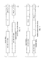
- FIG. 6 shows the timing diagram where the calling modem 110 has initiated retraining.
- the calling modem 110 stops sending data after failing to detect the test signal from the answering modem 120 in the Nth frame.
- the calling modem 110 transmits the tone B signal and conditions its receiver 205 to receive the INFOa0 signal.
- the answering modem 120 stops transmitting data and transmits the INFOa0 signal.
- the answering modem 120 transmits the A and A* signals. After transmitting the INFOc0 signal, the calling modem transmits the tone B signal. At this point 610, the retraining procedure continues accordingly from time 410 of phase two of the startup procedure as shown in figure 4.
- Figure 7 shows the answering modem 120 initiating the retraining of the modems.
- the answering modem 120 After failing to detect a test signal from the calling modem 110 in the Nth frame, the answering modem 120 transmits silence and waits for the second test signal.
- the answering modem 120 Upon failing to receive a second test signal, the answering modem 120 initiates retraining by transmitting the tone A signal and conditions its receiver to receive the INFOc0 signal.
- the calling modem 110 transmits the INFOc0 signal.
- the answering modem 120 Upon receiving the INFOc0 signal, the answering modem 120 then transmits the INFOa0 signal.
- the calling modem 110 After transmitting the INFOc0 signal, the calling modem 110 transmits the tone B signal.
- the answering modem 120 After receiving the tone B signal, the answering modem 120 transmits the tone A signal followed by the tone A* signal.
- the retraining procedure continues accordingly from time 410 of phase two of the startup procedure as shown in figure 4.
- the INFOa0 and INFOc0 are not transmitted during retraining.
- the modems proceed again through phases two, three, and four (see figures 4 and 5).
- the parameters or coefficients in the channel compensation modules established or set during the start up procedure are cleared, and new parameters or coefficients are determined and stored in the appropriate buffers.
- either modem upon a failure to detect the test signal, can initiate retraining by returning to phase three (See figure 5) where the echo canceller and equalizer are retrained.
- the initiating modem transmits the S signal followed by an S* signal (See Figure 5). If after proceeding through retraining initiated from phase three, one of the modems still does not receive the test signal, then that modem will initiate retraining and return to phase two by transmitting the A or B signal depending on which modem is initiating retraining.
- either modem may terminate the call by transferring an end command transfer signal in step 370.
- the present invention is describe as being implemented in a full duplex, V.34 standard, the present invention can also be implemented in other data transferring standards and algorithms that transmit data in a frame structure.
- the present invention may also be implemented in networks or data transferring systems, other than telephone networks, where data can be transferred in a frame structure.
Landscapes
- Engineering & Computer Science (AREA)
- Computer Networks & Wireless Communication (AREA)
- Signal Processing (AREA)
- Telephonic Communication Services (AREA)
- Communication Control (AREA)
Claims (10)
- Procédé pour transmettre des données sur un réseau (130) dans lequel :caractérisé en ce queles données sont transmises sur le réseau par un premier modem (110), les données incluant un signal de test ;le signal de test est reçu, venant du réseau par un second modem (120) ;le signal de test reçu par le second modem est comparé à un signal de test standard ; et une réorganisation est initiée sélectivement en réponse à la comparaison ;
un signal d'information est transmis sur le réseau par le premier modem, le signal d'information indiquant que le premier modem est capable de transmettre un signal de test ;
le signal d'information est reçu, venant du réseau, par le second modem, et un second signal d'information est transmis sur le réseau par le second modem, le second signal d'information indiquant que le second modem est capable de comparer le signal de test avec un signal de test standard. - Procédé selon la revendication 1 dans lequel :le second signal d'information est reçu, venant du réseau, par le premier modem ;le premier modem étant conditionné pour transmettre le signal de test avec les données sur le réseau en réponse au second signal d'information reçu par le premier modem indiquant que le second modem est capable de comparer le signal de test avec le signal de test standard.
- Procédé selon la revendication 1 ou la revendication 2 dans lequel les signaux d'information sont transmis sur le réseau pendant une procédure de démarrage.
- Procédé selon l'une quelconque des revendications précédentes, dans lequel le premier modem transmet le signal de test suivant des intervalles prédéterminés pendant la transmission des données.
- Procédé selon l'une quelconque des revendications précédentes dans lequel :les données sont transmises sur le réseau par le second modem, les données comportant un second signal de test ;le second signal de test est reçu, venant du réseau, par le premier modem ;le second signal de test reçu par le premier modem est comparé à un second signal de test standard ; etla réorganisation est initiée sélectivement comme cela est déterminé par la comparaison.
- Procédé selon l'une quelconque des revendications précédentes dans lequel :les données sont groupées en trames par le premier modem ;le nombre de trames est compté ; etla comparaison dépend du résultat du comptage.
- Modem (110) comprenant :caractérisé en ce que le modem est adapté pour transmettre un signal d'information sur le réseau indiquant que le modem est capable d'insérer le second signal de test dans la seconde pluralité de données.un récepteur (210) pour recevoir des signaux issus d'un réseau (130) dans lequel, dans un premier mode, les signaux contiennent une première pluralité de données provenant d'un système d'ordinateur (105) couplé au réseau, les signaux incluant également un premier signal de test contenu dans la première pluralité de données ; le récepteur comportant, de plus :l'ensemble de paramètres étant réinitialisé comme déterminé par un résultat du récepteur comparant le premier signal de test à un signal de test standard ;un module de compensation de canal (254, 263) adapté pour modifier les signaux reçus à partir du réseau, pour s'ajuster à au moins un état du réseau, le module de compensation de canal étant adapté pour modifier les signaux par l'intermédiaire d'un ensemble de paramètres ;un organisateur de trame (218) pour recevoir une seconde pluralité de données provenant d'un second système d'ordinateur (101), l'organisateur de trames étant adapté pour insérer un second signal de test dans une seconde pluralité de données ;
- Modem selon la revendication 7 dans lequel le signal d'information indique, de plus, la fréquence à laquelle l'organisateur de trame insère le second signal de test dans la seconde pluralité de données.
- Modem selon la revendication 7 dans lequel l'organisateur de trames est adapté pour insérer le second signal de test dans la seconde pluralité de données à intervalles prédéterminés.
- Modem (110) comprenant :caractérisé en ce que les signaux à un moment spécifié contiennent un signal d'information, le moment spécifié se produisant lorsque le modem ne se trouve pas dans le premier mode, le signal d'information indiquant que les signaux contiendront le premier signal de test avec la première pluralité de données.un récepteur (210) pour recevoir des signaux provenant d'un réseau (130), dans lequel suivant un premier mode, les signaux contiennent une première pluralité de données provenant d'un système d'ordinateur (105) couplé au réseau, les signaux incluant également un premier signal de test contenu dans la première pluralité de données ;le récepteur comprenant, de plus :un module de compensation de canal (254, 263) adapté pour modifier les signaux reçus à partir du réseau pour s'ajuster à au moins un état du réseau, le module de compensation de canal étant adapté pour modifier les signaux par l'intermédiaire d'un ensemble de paramètres ;l'ensemble de paramètres étant réinitialisé comme déterminé par un résultat du récepteur comparant le premier signal de test à un signal de test standard ;
Applications Claiming Priority (3)
| Application Number | Priority Date | Filing Date | Title |
|---|---|---|---|
| US08/853,300 US6374375B1 (en) | 1997-05-09 | 1997-05-09 | Monitoring line conditions in the data transmission mode |
| US853300 | 1997-05-09 | ||
| PCT/US1998/009305 WO1998051031A1 (fr) | 1997-05-09 | 1998-05-06 | Surveillance de l'etat des lignes en mode de transmission de donnees |
Publications (2)
| Publication Number | Publication Date |
|---|---|
| EP0980606A1 EP0980606A1 (fr) | 2000-02-23 |
| EP0980606B1 true EP0980606B1 (fr) | 2004-11-17 |
Family
ID=25315660
Family Applications (1)
| Application Number | Title | Priority Date | Filing Date |
|---|---|---|---|
| EP98922123A Expired - Lifetime EP0980606B1 (fr) | 1997-05-09 | 1998-05-06 | Surveillance de l'etat des lignes en mode de transmission de donnees |
Country Status (4)
| Country | Link |
|---|---|
| US (1) | US6374375B1 (fr) |
| EP (1) | EP0980606B1 (fr) |
| DE (1) | DE69827620T2 (fr) |
| WO (1) | WO1998051031A1 (fr) |
Families Citing this family (18)
| Publication number | Priority date | Publication date | Assignee | Title |
|---|---|---|---|---|
| KR100263478B1 (ko) * | 1998-02-04 | 2000-08-01 | 김영환 | 모뎀의 접속 방법 |
| KR100264787B1 (ko) | 1998-06-15 | 2000-09-01 | 김영환 | 이동통신 시스템의 핸드오프 제어방법 |
| US6650698B1 (en) * | 1999-09-29 | 2003-11-18 | Conexant Systems, Inc. | Non-linear equalization for the upstream data connection of 56K PCM modems |
| US6546045B1 (en) * | 1999-11-16 | 2003-04-08 | United States Of America | Method for communication using adaptive modem |
| US7106788B1 (en) * | 1999-11-19 | 2006-09-12 | 3Com Corporation | Method and system for analytically computing and using an ANSpcm signal |
| US6687232B1 (en) * | 2000-01-14 | 2004-02-03 | Adtran, Inc. | Subscriber loop terminal equipment-resident mechanism for determining bit rate of high-level data link control communication channel |
| EP1250766B1 (fr) * | 2000-01-25 | 2008-09-17 | Aware, Inc. | Systeme et procede d'application d'une methode des moindres carres pour actualiser un annuleur d'echo dans un modem lnpa |
| US7013257B1 (en) * | 2000-07-21 | 2006-03-14 | Interdigital Technology Corporation | Communication transmission impairment emulator |
| US7076556B1 (en) * | 2000-07-31 | 2006-07-11 | Cisco Technology, Inc. | Method and apparatus for storage and retrieval of connection data in a communications system |
| US6693992B2 (en) * | 2001-01-16 | 2004-02-17 | Mindspeed Technologies | Line probe signal and method of use |
| US20030068024A1 (en) * | 2001-10-05 | 2003-04-10 | Jones William W. | Communication system activation |
| US7400670B2 (en) | 2004-01-28 | 2008-07-15 | Rambus, Inc. | Periodic calibration for communication channels by drift tracking |
| US8422568B2 (en) | 2004-01-28 | 2013-04-16 | Rambus Inc. | Communication channel calibration for drift conditions |
| US7095789B2 (en) | 2004-01-28 | 2006-08-22 | Rambus, Inc. | Communication channel calibration for drift conditions |
| US6961862B2 (en) | 2004-03-17 | 2005-11-01 | Rambus, Inc. | Drift tracking feedback for communication channels |
| US20080155159A1 (en) * | 2006-12-22 | 2008-06-26 | Rivas Mario A | Integrated communication and information processing system |
| US10476599B2 (en) * | 2016-04-18 | 2019-11-12 | Nec Corporation | Joint source and LDPC coding based coding modulation for ultra-high-speed optical transport |
| CN116366415A (zh) * | 2021-12-27 | 2023-06-30 | 华为技术有限公司 | 调制方法、解调方法以及相关装置 |
Family Cites Families (5)
| Publication number | Priority date | Publication date | Assignee | Title |
|---|---|---|---|---|
| JPH0773240B2 (ja) | 1985-12-13 | 1995-08-02 | 日本電気株式会社 | 自動再トレ−ニング方式 |
| GB8800740D0 (en) * | 1988-01-13 | 1988-02-10 | Ncr Co | Data modem receiver |
| US4956851A (en) * | 1988-05-25 | 1990-09-11 | Case Communications Inc. | Modem with remote speed-change capability |
| US5408475A (en) | 1990-06-14 | 1995-04-18 | Motorola, Inc. | Modem with transient impairment detector |
| US5214637A (en) * | 1991-04-15 | 1993-05-25 | Codex Corporation | High speed two wire modem |
-
1997
- 1997-05-09 US US08/853,300 patent/US6374375B1/en not_active Expired - Lifetime
-
1998
- 1998-05-06 EP EP98922123A patent/EP0980606B1/fr not_active Expired - Lifetime
- 1998-05-06 WO PCT/US1998/009305 patent/WO1998051031A1/fr not_active Ceased
- 1998-05-06 DE DE69827620T patent/DE69827620T2/de not_active Expired - Lifetime
Also Published As
| Publication number | Publication date |
|---|---|
| DE69827620T2 (de) | 2005-12-01 |
| US6374375B1 (en) | 2002-04-16 |
| WO1998051031A1 (fr) | 1998-11-12 |
| EP0980606A1 (fr) | 2000-02-23 |
| DE69827620D1 (de) | 2004-12-23 |
Similar Documents
| Publication | Publication Date | Title |
|---|---|---|
| EP0980606B1 (fr) | Surveillance de l'etat des lignes en mode de transmission de donnees | |
| EP0292691B1 (fr) | Protocole rapide pour le changement de la direction du trafic pour un modem semi-duplex à grande vitesse | |
| US5025469A (en) | Method and apparatus for reducing the turn-around time in facsimile transmission | |
| US6704399B1 (en) | Quick connect parameter exchange | |
| US5793809A (en) | Transparent technique for Mu-law modems to detect an all-digital circuit connection | |
| US5054020A (en) | Apparatus for high speed data communication with asynchronous/synchronous and synchronous/asynchronous data conversion | |
| JPH0211057A (ja) | データ通信方法と通信ネットワーク | |
| US6574280B1 (en) | Method and apparatus for detecting and determining characteristics of a digital channel in a data communication system | |
| US5394392A (en) | Method for transferring information using modems | |
| US20030123487A1 (en) | SHDSL over POTS | |
| Inoue et al. | Time-shared two-wire digital subscriber transmission system and its application to the digital telephone set | |
| WO1999027702A1 (fr) | Mise en communication d'equipements terminaux | |
| CA2257769A1 (fr) | Methode d'amelioration de donnees en frequences vocales | |
| US6414989B1 (en) | Upstream PCM transmission for a modem system | |
| US6501790B1 (en) | Method and apparatus for providing high speed modem replay using locally connecting modems | |
| US6452963B1 (en) | Method for connecting modems | |
| US6600780B1 (en) | Apparatus and method for adapting a filter of an analog modem | |
| KR20030012842A (ko) | Pcm을 이용하는 디지털 및 아날로그 모뎀들을 위한시동 절차 방법 및 장치 | |
| US6266382B1 (en) | Technique for detecting and treating robbed bit signaling in data communications | |
| EP1201077B1 (fr) | Echange de parametres rapide | |
| US6081556A (en) | Transparent technique for Mu-law modems to detect an all-digital circuit connection | |
| US11736621B2 (en) | Method of quick connection of PSTN modems and PSTN modem with fast connection according to such method | |
| EP0478205B1 (fr) | Appareil pour la transmission numérique d'appels fac-similés utilisant détection et regénération de tonalité de protection contre l'écho | |
| EP1709507A2 (fr) | Solution d'intercommunication entre modems pour passerelles telephoniques | |
| CA1254314A (fr) | Systeme telephonique et methode de transmission de donnees numeriques |
Legal Events
| Date | Code | Title | Description |
|---|---|---|---|
| PUAI | Public reference made under article 153(3) epc to a published international application that has entered the european phase |
Free format text: ORIGINAL CODE: 0009012 |
|
| 17P | Request for examination filed |
Effective date: 19990930 |
|
| AK | Designated contracting states |
Kind code of ref document: A1 Designated state(s): DE GB |
|
| GRAP | Despatch of communication of intention to grant a patent |
Free format text: ORIGINAL CODE: EPIDOSNIGR1 |
|
| GRAS | Grant fee paid |
Free format text: ORIGINAL CODE: EPIDOSNIGR3 |
|
| RAP1 | Party data changed (applicant data changed or rights of an application transferred) |
Owner name: LEGERITY, INC. |
|
| GRAA | (expected) grant |
Free format text: ORIGINAL CODE: 0009210 |
|
| AK | Designated contracting states |
Kind code of ref document: B1 Designated state(s): DE GB |
|
| REG | Reference to a national code |
Ref country code: GB Ref legal event code: FG4D |
|
| REF | Corresponds to: |
Ref document number: 69827620 Country of ref document: DE Date of ref document: 20041223 Kind code of ref document: P |
|
| PLBE | No opposition filed within time limit |
Free format text: ORIGINAL CODE: 0009261 |
|
| STAA | Information on the status of an ep patent application or granted ep patent |
Free format text: STATUS: NO OPPOSITION FILED WITHIN TIME LIMIT |
|
| 26N | No opposition filed |
Effective date: 20050818 |
|
| PGFP | Annual fee paid to national office [announced via postgrant information from national office to epo] |
Ref country code: GB Payment date: 20110421 Year of fee payment: 14 |
|
| PGFP | Annual fee paid to national office [announced via postgrant information from national office to epo] |
Ref country code: DE Payment date: 20110531 Year of fee payment: 14 |
|
| GBPC | Gb: european patent ceased through non-payment of renewal fee |
Effective date: 20120506 |
|
| REG | Reference to a national code |
Ref country code: DE Ref legal event code: R119 Ref document number: 69827620 Country of ref document: DE Effective date: 20121201 |
|
| PG25 | Lapsed in a contracting state [announced via postgrant information from national office to epo] |
Ref country code: GB Free format text: LAPSE BECAUSE OF NON-PAYMENT OF DUE FEES Effective date: 20120506 |
|
| PG25 | Lapsed in a contracting state [announced via postgrant information from national office to epo] |
Ref country code: DE Free format text: LAPSE BECAUSE OF NON-PAYMENT OF DUE FEES Effective date: 20121201 |