BACKGROUND OF THE INVENTION
FIELD OF THE INVENTION:
The present invention relates to a road sign
sensing system and more particularly, to a road sign
sensing system which can detect a road sign digitally
displayed on a road with use of a vehicle sensor.
DESCRIPTION OF THE RELATED ART:
Conventional road signs are displayed on poles at
road sides or on road surfaces in the form of character or
symbol signs including, e.g., a "speed limit" sign, a
"stop" sign, a "pedestrian crossing" sign and a "coming
crossing notice" sign. A vehicle driver, after visually
confirming such a road sign, slows down or stops his or her
car. In this way, the sign reflects on his or her driving
by such car control.
In a conventional road sign sensing system, road
conditions varying with time are guided by means of a light
sign board or the like. Further, it is suggested to
audibly or visually inform drivers of traffic information
or to control vehicles by means of an electromagnetic wave
or optical signal.
However, such conventional road signs have a
problem that, since the driver visually reads such a sign,
the car control can be realized only by the driver and the
road sign information cannot be directly used as vehicle
drive control data. The conventional road sign sensing
system has another problem that, since the system requires
provision of means for directly informing the vehicle of
road information by means of radio communication, it will
involve high costs and a new system in the upgrading of
road infrastructure, which impractically involves a lot of
time and cost.
It is obvious that the degree of safety can be
improved by the fact that a driver can reliably know the
conditions of a road on which driver's car is running and
its surrounding circumstances. Accordingly, in order to
safely drive the car, it is necessary for the driver to
reliably take information from road signs. It is however
highly difficult for the driver to visually confirm all the
road signs during his car drive for his constant safe and
reliable drive. Further, in case that road signs are
written only in Japanese, the signs disadvantageously
becomes meaningless for non-Japanese drivers.
SUMMARY OF THE INVENTION
It is therefore an object of the present
invention to provide a road sign sensing method and system
which can directly read road signs and visually or audibly
inform a driver of information about the road signs to
thereby realize his enhanced safe driving.
In accordance with the present invention, the
above object is attained by providing on a road surface or
side wall of express highway and non-expressway roads such
a digital signal sign as to display to running cars
information about the road speed limit, presence or absence
of a pedestrian crossing or a curve, under-construction
section, road circumstances, etc. With such an arrangement,
it becomes possible for a running car to read
digitally displayed data about road signs via a sensor
mounted in the car and to inform the driver of the data on
a video monitor or by means of a sounding device both
mounted within the car. Even when the car is running at a
high speed, it is unnecessary for the driver to visually
read the road signs, whereby the driver can concentrate on
his driving alone. Further, since the digital signal signs
can be displayed with conventional white paint, it becomes
unnecessary to add a further facility for the road display.
BRIEF DESCRIPTION OF THE DRAWINGS
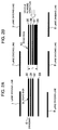
Figs. 1A to 1C show road sign display systems in
accordance with a first embodiment of the present
invention;
Figs. 2A and 2B show road sign display systems in
accordance with a second embodiment of the present
invention;
Fig. 3 shows a road sign display system in
accordance with a third embodiment of the present
invention;
Fig. 4 shows another road sign display system in
accordance with the third embodiment of the present
invention;
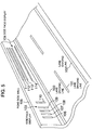
Fig. 5 shows a road sign display system in
accordance with a fourth embodiment of the present
invention;
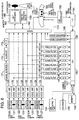
Fig. 6 shows a functional block diagram of a road
sign sensing system in accordance with a fifth embodiment
of the present invention;
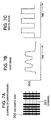
Figs. 7A to 7C are diagrams for explaining the
scanning operation of the road sign sensing system of the
fifth embodiment of the invention;
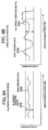
Figs. 8A and 8B are diagrams for explaining how
to detect a roll in the road sign sensing system of the
fifth embodiment of the invention; and
Figs. 9A and 9B are diagrams for explaining how
to detect a dirt in the road sign sensing system of the
fifth embodiment of the invention.
DETAILED DESCRIPTION OF THE EMBODIMENTS
The present invention will be detailed in connection
with embodiments of the invention with reference to
Figs. 1 to 9.
(First Embodiment)
In a road sign display system in accordance with
a first embodiment of the present invention, a sign of bars
in a direction perpendicular to running directions of
vehicles is drawn on a surface of a road to provide a
digital indication for the road sign.
Figs. 1A to 1C show road sign display systems in
accordance with the first embodiment of the present
invention. In Figs. 1A to 1C, a driveway 1 is a paved road
such as a highway road or a non-expressway or ordinary
road. Lane dividing lines 2 and 3 are white or yellow
lines for defining a lane on the driveway 1. A road sign 4
shown in Fig. 1A is a digital road sign which includes a
plurality of bars drawn in a middle area of the lane and a
difference in interval between the bars denotes "0" or "1".
A road sign 5 shown in Fig. 1B is a digital road sign which
includes a plurality of bars drawn in a middle area of the
lane and a difference in width of the bar denotes "0" or
"1". A road sign 41 shown in Fig. 1C is a digital road
sign which includes a plurality of bars drawn in a middle
area of the lane and a difference in width of the bar
denotes "0" or "1".
Explanation will be made in detail as to the road
sign display systems in accordance with the first embodiment
of the present invention, by referring to Figs. 1A to
1C.
In the road sign display system shown in Fig. 1A,
eight bars 11 to 18 each having an equal width are drawn in
the middle of the driveway 1 as extended in direction
perpendicular to the car moving direction like supports on
'geta' (wooden sandals). Digital data indicated by the
bars 11 to 18 are recognized by photographing the bars 11
to 18 with use of a cameras sensor mounted onto the car
during running of the car.
More specifically, when an interval between the
adjacent bars, e.g., between the bars 11 and 12 is small,
it is recognized as digital data of "0". When an interval
between the adjacent bars, e.g., between the bars 15 and 16
is large, it is recognized as digital data of "1". Accordingly,
the illustrated 8 bars 11 to 18 are recognized as
digital data of "0, 0, 0, 0, 1, 0, 0".
In this way, in the road sign display system,
when 5 bars are drawn, the bars can indicate 4-bit digital
data and therefore 16 road signs can be transmitted to the
car driver. Further, when 7 bars are drawn, the bars can
indicate 6-bit digital data and therefore 64 road signs can
be transmitted to the car driver.
In the road sign display system shown in Fig. 1B,
eight bars 19 to 26 having different widths are drawn in
the middle of the driveway lane 1 as extended in a
direction perpendicular to the car moving direction like
supports on 'geta' (wooden sandals). Digital data
indicated by the bars 19 to 26 are recognized by photographing
the bars 19 to 26 with use of a camera sensor
mounted onto the car during running of the car.
More specifically, when the bar width is small
like the bars 19 to 23, 25 and 26, it is recognized as
digital data of "0". When the bar width is large like the
bar 24, it is recognized as digital data of "1". Accordingly,
the illustrated 8 bars 19 to 26 are recognized as
digital data of "0, 0, 0, 0, 0, 1, 0, 0".
In this way, in this road sign display system,
when 4 bars are drawn, the bars can indicate 4-bit digital
data and therefore 16 road signs can be transmitted to the
car driver. Further, when 6 bars are drawn, the bars can
indicate 6-bit digital data and therefore 64 road signs can
be transmitted to the car driver.
In the road sign display system shown in Fig. 1C,
eight bars 19' to 25' having different widths are drawn as
substantially fully extended up to the side extremes of the
driveway lane 1 in direction perpendicular to the car
moving direction like supports on 'geta' (wooden sandals).
In other words, in this road sign display system, length L2
of the bars 19' to 25' is made longer than length L1 of the
bars 19 to 26 of Fig. 1B.
In the road sign display system of Fig. 1B,
length L1 of the bars 19 to 26 is set so that the tires of
the car will not come into contact with the bars 19 to 26
so long as the car is normally running within the lane.
When the car is unstably running to right or left side, on
the other hand, the car tires come into contact with the
bars 19 to 26 and thus its running sound becomes changed.
Thus, the car driver can know the fact that the car is not
running in the middle of the lane based on the car running
sound, which also can help driver's safety driving.
Meanwhile, in the road sign display system of Fig. 1C, the
bars 19' to 25' drawn as substantially fully extended up to
the extremes of the width of the lane can play a role of a
brake indication which informs the driver of necessity of
brake application for a coming long downhill slope, or a
role of a drowsiness preventing indication which informs
the driver of keeping him awake as on such a long straight
road as induce drowsiness.
In this connection, even when the bars 11 to 18
of Fig. 1A are drawn as fully extended up to the extremes
of the width of the driveway lane 1, the road sign display
system of Fig. 1A can have substantially the same effects
as the road sign display system of Fig. 1C.
Since road signs are important, it is necessary
to always inform the driver of data on these signs. To
this end, when the bars 11 to 26 and 19' to 25' may not be
read out by the camera sensor mounted on the car due to
snowfall, means for always causing flowing of water onto
the bars 11 to 26 and 19' to 25' may be provided in order
to avoid the bars from being covered with snow. Further,
in order to avoid snow from heap on the bars, heaters may
be provided under the bars 11 to 26 and 19' to 25'.
Furthermore, in order that the camera sensor can
sufficiently read the barsll to 26 and 19' to 25' at night,
the material of the bars 11 to 26 and 19' to 25' may
contain fluorescent substance. In addition, for the
purpose of giving the driver a clearer view of the bars 11
to 26 and 19' to 25', illuminating means may be provided
within the bars 11 to 26 and 19' to 25'. In this case,
when the road is covered with a glass material to allow
light of the illuminators within the bars 11 to 26 and 19'
to 25' to be transmitted through the glass, the driver can
clearly read the bars 11 to 26 and 19' to 25'.
As has been explained above, in the road sign
display systems in accordance with the first embodiment of
the present invention, when bar-shaped signs are drawn on
the lane as extended in the direction perpendicular to the
car running direction, the car driver can reliably get
information on the bar-shaped signs during car drive.
(Second Embodiment)
In a road sign display system in accordance with
a second embodiment of the present invention, a sign of
bars extended in a direction parallel to the car moving
direction is drawn on a road for its digital display.
Figs. 2A and 2B show road sign display systems in
accordance with the second embodiment of the present
invention. In Figs. 2A and 2B, a driveway 6 is a paved
road such as a highway road or a non-expressway or ordinary
road. Lane dividing lines 7 and 8 are white or yellow
lines for defining a lane on the driveway 6. A road sign 9
shown in Fig. 2A is a digital road sign which includes a
plurality of bars drawn in a middle area of the lane and a
difference in interval between the bars denotes "0" or "1".
A road sign 10 shown in Fig. 2B is a digital road sign
which includes a plurality of bars drawn in a middle area
of the lane and a difference in width of the bar denotes
"0" or "1".
Explanation will be made in detail as to the road
sign display systems in accordance with the second embodiment
of the present invention, by referring to Figs. 2A and
2B.
In the road sign display system shown in Fig. 2A,
4 bars 30 to 33 each having an equal width are drawn on the
lane in a direction parallel to the car moving direction.
When the bars 30 to 33 are drawn in the direction parallel
to the car moving direction, a detector (such as a camera
sensor) mounted on the car can detect digital data
indicated by the bars 30 to 33 for a long time, the driver
can confirm the digital data detected during the car
running.
More specifically, when an interval between the
adjacent bars, e.g., between the bars 30 and 31 is small,
it is recognized as digital data of "0". When an interval
between the adjacent bars, e.g., between the bars 32 and 33
is large, it is recognized as digital data of "1". Accordingly,
the illustrated 4 bars 30 to 33 are recognized as
digital data of "0, 0, 1".
In the road sign display system shown in Fig. 2B,
4 bars 35 to 38 having different widths are drawn as
extended in a direction parallel to the car moving
direction. When the bar width is small like the bars 35 to
37, it is recognized as digital data of "0". When the bar
width is large like the bar 38, it is recognized as digital
data of "1". Accordingly, the illustrated 4 bars 35 to 38
are recognized as digital data of "0, 0, 0, 1".
The 4 bars 30 to 33 shown in Fig. 2A as well as
the 4 bars 35 to 38 shown in Fig. 2B are drawn on the lane
to have such length L that the tires of the car will not
come into contact with the bars 30 to 33 and 35 to 38 so
long as the car is normally running. When the car is
unstably running to right or left side, on the other hand,
the car tires come into contact with the bars 30 to 33 and
35 to 38, and thus its running sound becomes changed.
Thus, the car driver can know the fact that the car is not
running in the middle of the lane based on the car running
sound, which also can help driver's safety driving.
As has been explained above, in the road sign
display systems in accordance with the second embodiment of
the present invention, when bar-shaped signs are drawn on
the lane as extended in the direction parallel to the car
running direction, the car driver can reliably get information
on the bar-shaped sign during car drive, because the
detector on the car can detect the bar-shaped sign for a
long time.
(Third Embodiment)
In a road sign display system in accordance with
a third embodiment of the present invention, lane dividing
lines are used for digital display of a road sign.
Figs. 3 and 4 show road sign display systems in
accordance with the third embodiment of the present
invention. In Fig. 3, a driveway 50 is a paved road such
as a highway road or a non-expressway or ordinary road.
Lane dividing lines 541 and 542 are white or yellow lines
for defining a lane on the driveway 50. A car 51 is a car
running on the lane of the driveway 50. Camera sensors 52
and 53 are mounted on front left and right sides of the car
51, respectively. In Fig. 4, a driveway 98 is a paved road
such as a highway road or a non-expressway or ordinary
road. Lane dividing lines 931 and 932 are white or yellow
lines for defining a lane on the driveway 98. A car 95 is
a car running on the lane of the driveway 98. Camera
sensors 96 and 97 are mounted on front left and right sides
of the car 51, respectively.
Explanation will be made in detail as to the road
sign display system of the third embodiment of the present
invention, by referring to Figs. 3 and 4.
In the road sign display system of Fig. 3, the
lane dividing lines 541 and 542 are made discontinuous into
bars having intervals 55 to 64 and 65 to 74 therebetween to
display a road sign (digital data) based on the bar
intervals. Digital data about the sign is read out into
the car by the camera sensors 52 and 53 provided on the
left and right sides of the car 51 which function to read
out the intervals 55 to 64 and 65 to 74. When the interval
between the adjacent bars of the discontinuous lane
dividing line 541 is small as the interval 55 between the
adjacent bars, it is recognized as digital data of "0".
When the interval between the adjacent bars of the lane
dividing line 541, on the other hand, is large as the
interval 61 between the adjacent bars, it is recognized as
digital data of "1". Accordingly, in the illustrated
example, digital data indicated by the intervals 55 to 64
of the adjacent bars of the lane dividing line 541 and by
the intervals 65 to 74 of the adjacent bars of the lane
dividing line 542 is recognized as digital data of "0, 0, 0,
0, 0, 0, 1, 0, 0, 0".
In this way, in this road sign display system,
since road sign information can be indicated along the car
running lane, road sign information of multiple bits such
as 8 bits or 16 bits also can be indicated. Further, when
an identical road sign (digital data) is displayed as
repeated, its road sign reading reliability can be
increased.
Further, when the same road sign is displayed
with use of the lane dividing lines 541 and 542 at the both
sides of the driveway 50, the road sign reading reliability
can be increased. Furthermore, when navigation information
(e.g., on lane destination) is set in one of the lane
dividing lines 541 and 542, the car 51 also can run on a
navigation basis.
In the road sign display system of Fig. 4, lane
dividing lines 931 and 932 are made discontinuous into bars
75 to 83 and 84 to 92 to display a road sign (digital data)
based on lengths of the bars. Digital data about the bars
are read out into the car 95 by the sensors 96 and 97
mounted on the left and right sides of the car 95 for
reading the lengths of the bars 75 to 83 and 84 to 92.
When the length of one of the divided bars of the lane
dividing line 931 is small like that of the bar 75, it is
recognized as digital data of "0". When the length of one
of the divided bars of the lane dividing line 931 is large
like that of the bar 81, it is recognized as digital data
of "1". Accordingly, in the illustrated example, digital
data indicated by the bars 75 to 83 of the lane dividing
line 931 and by the bars 84 to 92 of the lane dividing line
932 are recognized as digital data of "0, 0, 0, 0, 0, 0, 1,
0, 0".
In this way, this road sign display system can
have substantially the same effects as the road sign
display system of Fig. 3, since the system can display road
sign information along the car running lane. Even in this
road sign display system, like the road sign display system
of Fig. 3, the lane dividing lines 931 and 932 may be used
to display an identical road sign (digital data) or to
display different road signs. Further, when the lane
dividing lines 931 and 932 are used to display different
road sign (digital data), information about the position of
the car 95 and information about a next coming road at a
fork road of an expressway can be informed to the driver.
As has been explained in the foregoing, since the
road sign display system in accordance with the third
embodiment of the present invention is arranged to display
the bar-shaped sign with use of the lane dividing lines,
the system can display not only the road sign but also
information on navigation, car position and expressway fork
road.
(Fourth Embodiment)
In a road sign display system in accordance with
a fourth embodiment of the present invention, a bar-shaped
sign is drawn on a side wall of a road to digitally display
the sign.
Fig. 5 shows a road sign display system in
accordance with the fourth embodiment of the present
invention. In Fig. 5, lane dividing lines 100, 101 and 102
are lines for defining the lane. Side face displays 103
and 104 are signs of bars each including a plurality of
bars drawn on a median strip or side wall of a road. A
road side wall 105 is a median strip or a side wall of the
road. When a median strip for lane division or the road
side wall 105 is used to display a road sign (digital
data), the road sign can be always read out even in a
region where it often hard to see road faces at the time of
snowfall or rainfall.
The side face display 103 drawn on the road side
wall 105, like the road sign 4 shown in Fig. 1A, is a sign
of bars which shows a road sign (digital data) indicative
of a vehicle division or the like based on intervals of
bars 106 to 110 and which is drawn as extended in a
direction perpendicular to the car moving direction. In
this connection, the side face display 103, like the road
sign 5 shown in Fig. 1B, may be a sign of bars which shows
a road sign (digital data) indicative of a vehicle division
or the like based on widths of the bars 106 to 110 and
which is drawn as extended in a direction perpendicular to
the car moving direction. The side face display 104 drawn
on the road side wall 105, like the road sign 9 shown in
Fig. 2A, is a sign of bars which shows a road sign (digital
data) indicative of a vehicle division or the like based on
intervals of bars 111 to 114 and which is drawn as extended
in a direction parallel to the car moving direction. In
this connection, the road side wall 105, like the road sign
10 of Fig. 2B, may be a sign of bars which shows a road
sign (digital data) indicative of a vehicle division or the
like based on widths of 111 to 114 and which is drawn as
extended in a direction parallel to the car moving lane.
As has been explained above, in the road sign
display system of the fourth embodiment of the invention,
the road sign is digitally displayed in the form of the
bar-shaped sign drawn on the road side wall, so that, even
when it is hard for a car driver to clearly see the road
face at the time of snowfall or rainfall, the system can
always inform the driver of the road sign.
(Fifth Embodiment)
A road sign sensing system in accordance with a
fifth embodiment of the present invention reads a bar-shaped
sign with use of a camera sensor, converts the read
data to digital data, and informs a car driver of information
about the road sign.
Fig. 6 shows a road sign sensing system in
accordance with the fifth embodiment of the present
invention. In Fig. 6, a back camera 120, side cameras 122,
124 and a front camera 126 function as sensors for reading
a bar-shaped sign. Four microphones 121, 123, 125 and 127
receive external sound. Video amplification circuits 128,
131, 133 and 135 connected to the respective cameras 120,
122, 124 and 126 amplify video signals received from the
cameras 120, 122, 124 and 126. Voice amplification
circuits 130, 132, 134 and 136 connected to the respective
microphones 121, 123, 125 and 127 amplify voice signals
received from the microphones 121, 123, 125 and 127. Video
filters 138, 140, 142 and 144 connected to the respective
video amplification circuits 128, 131, 133 and 135 remove
unnecessary components in the amplified video signals.
Voice filters 137, 139, 141 and 143 connected to the
respective voice amplification circuits 130, 132, 134 and
136 remove unnecessary components in the amplified voice
signals. Analog/digital conversion (A/D) circuits 145 to
152 connected to the video amplification circuits 128, 131,
133 and 135 and voice amplification circuits 130, 132, 134
and 136 respectively convert the analog video signals and
analog voice signals to digital video signals and digital
voice signals.
A CPU 153 processes the digital video signals and
digital voice signals output from the A/D circuit 145 to
152 to control recording and display of the video and voice
signals. A CPU operating part 154 connected to the CPU 153
is input means such as a keyboard for operator's instruction
to the CPU 153 or processing selection. A recording
device 155 connected to the CPU 153 is a device which
records the video and voice signals. A memory 156
connected to the CPU 153 is a temporary memory for use in
processing of the CPU 153. The CPU operating part 154,
recording device 155 and memory 156 receives and sends
signal from and to the CPU 153 via a common interface 157.
A video conversion circuit 158 connected to the
CPU 153 converts such data as character data for display to
a video signal. A voice conversion circuit 159 connected
to the CPU 153 converts digital data to a voice signal. A
speed information signal 160 is a speed signal received
from a car speedometer. An interface (I/F) 161 is an
interface through which the speed information signal 160 is
input from a vehicle controller 162 to the CPU 153.
The vehicle controller 162 controls the respective
parts of the vehicle or collects output signals from
the sensors. A vehicle display unit 163 displays a vehicle
speed, traveled distance, position, etc. thereon. A
vehicle dashboard 164 accommodates the speedometer, etc.
therein. A mixing circuit 165 performs mixing operation of
video, voice and data. A character display 166 is a
message displayed on a monitor 167. The monitor 167 is a
display unit such as a cathode-ray tube (CRT) which
displays video data received from the CPU 153 thereon. A
loudspeaker 168 outputs voice information from the CPU 153.
A display operating device 169 is an input device by which
the operator issues an instruction to the mixing circuit
165 to instruct the circuit of a display type, method, etc.
A voice indication 170 is a voice message output from the
loudspeaker 168.
A level detection circuit 171 compares a level of
the video signal received from the camera with a predetermined
threshold value. An alarm circuit 172 connected to
the level detection circuit 171 outputs an alarm signal
when the level of the video signal exceeds the predetermined
threshold value. An analog/digital conversion (A/D)
circuit 173 connected to the alarm circuit 172 converts an
analog alarm signal to a digital alarm signal and outputs
the digital alarm signal to the CPU 153. Display data 174
output from the CPU 153 includes data about a position
which is to be displayed on the vehicle display unit 163.
Figs. 7A to 7C are diagrams for explaining how to
convert a bar-shaped sign to a digital signal in the road
sign sensing system in accordance with the fifth embodiment
of the present invention. In Fig. 7A, a bar-shaped sign
200 is an exemplary road sign drawn on a road face.
Scanning 201 is for explaining how to scan the sign with
use of the cameras 120, 122, 124 and 126. Figs. 8A and 8B
are diagrams for explaining how to detect a roll in the
road sign sensing system of the fifth embodiment of the
present invention. In Figs. 8A and 8B, allowable variation
widths 202 and 205 denote normal variation ranges in which
variations in video signals of ends of a road sign (bar-shaped
sign) are regarded as normal. Road sign end data
203 and 204 each denotes a video signal indicative of an
end of a road sign (bar-shaped sign) shot by a camera.
Figs. 9A and 9B are diagrams for explaining how to detect a
dirt on the cameras in the road sign sensing system of the
fifth embodiment of the present invention. A normal level
206 in Fig. 9B denotes the level of the video signals of
the cameras 120, 122, 124 and 126 when the cameras have no
dirt thereon.
The operation of the road sign sensing system of
the fifth embodiment of the present invention will be
explained by referring to Figs. 6 to 9.
The front camera 126 mounted on a front part of
the vehicle is used to capture an image of the bar-shaped
sign (road sign) 200 drawn on a road face. In order to
accurately convert the image of the bar-shaped sign 200 to
digital data, the front camera 126 is mounted on the
vehicle so that the scanning line of the front camera 126
is vertical to each bar-shaped sign 200. That is, as shown
by the scanning 201 in Fig. 7A, when white and black
signals are arranged to be alternately output for data on
one of lines in the image, it becomes easy to reproduce the
image data as digital data. Therefore, the front camera
126 is mounted on the vehicle so that the camera performs
such scanning 201 as shown in Fig. 7A over the bar-shaped
sign 200 to efficiently read the bar-shaped sign 200.
The interval and width of bars in the bar-shaped
sign 200 read by the front camera 126 will vary with a
vehicle speed at which the vehicle transverses the bars of
the bar-shaped sign 200. To avoid this, the CPU 153
acquires vehicle information such as the speed information
signal 160 from the vehicle controller 162 ,and corrects
the interval and width of the bars in the bar-shaped sign
200 read by the front camera 126. After such a correction,
when the bar-shaped sign 200 is recognized as digital data,
information indicative of the bar-shaped sign 200 can be
correctly captured as the digital data. In this case,
however, the bar-shaped sign 200 is drawn as extended in a
direction perpendicular to the car moving direction. For
this reason, when the car is stopped due to a traffic jam,
the information indicative of the bar-shaped sign 200
cannot be read by the car.
However, in the case of such a bar-shaped sign
indicated by bars parallel to the car moving direction as
the bar-shaped signs 9 and 10 of Figs. 2A and 2B, regardless
of the fact that the car is running at a high speed or
is stopped, the digital data obtained by the front camera
126 are the same in the both situations. Accordingly, in
this case, since the same digital data can be displayed for
a long time, a sign reading error as a digital signal can
be minimized.
The video signal thus obtained is as shown in
Fig. 7B. The video signal is amplified by the video
amplification circuit 135, removed in its unnecessary
components by the video filter 144, and then converted by
the A/D converter 152 to such a digital video signal as
shown in Fig. 7C. On the basis of the converted digital
video signal, an image of the bar-shaped sign 200 is
processed and converted to digital data.
In the case of such displays as the road sign 4
of Fig. 1A, the road sign 5 of Fig. 1B, the lane dividing
lines 541 and 542 of Fig. 3, the lane dividing lines 931 and
932 of Fig. 4 and the side face display 103 of Fig. 5; since
the vehicle transverses these sign displays in a short
time, start and end bits are inserted at the beginning and
end of the reading data. When the recognition of the
digital data is started with the reading of data about the
start bit by vehicle sensor (such as the front camera 126
or side cameras 122 and 124), the digital data can be
accurately recognized. How to indicate the start and end
bits is selected according to the system application
purpose.
The digital data obtained based on the digital
video signal from the A/D converter 152 is collated in the
CPU 153 with data previously registered in the memory 156
and converted to road sign information indicative of the
bar-shaped sign 200.
For example, digital data are made associated
with road sign information as given in Table below.
| Relationship Between Digital Data And Road Sign
Information |
| Digital Data | Road Sign Information |
| 000001 | 50km Speed Limit |
| 000010 | Sharp Curve Ahead |
| 000100 | Pedestrian Crossing Ahead |
| 001000 | 100km Speed Limit |
| 010000 | Reduce Speed |
| 100000 | Fork Road Ahead |
The road sign information is converted to
characters or an image by the video conversion circuit 158.
In this way, since information on the speed, pedestrian
crossing, road, destination, distance, etc. are displayed
on the monitor 167 within the car, these information can
help safety driving. Similarly, the road sign information
is converted to a voice signal by the voice conversion
circuit 159. Thereby, the car driver can know the road
information from the loudspeaker 168 by his ears. Data
from the CPU 153 can also be displayed even on the vehicle
display unit 163 of the vehicle dashboard 164. Further,
the data from the CPU 153 may also be indicated in the form
of a lamp or symbol mark at the location of the vehicle
dashboard 164 where the speedometer, etc. are mounted.
When the digital data is recorded in the recording
device 155 for predetermined time, the driver can later
know how the car ran on the road. Thus, in case of a
traffic accident, the data can be later taken out as the
driven record and the cause analysis of the accident can be
carried out. Further, various types of digital data can be
accumulated in the recording device 155 for predetermined
time. For example, when the recording device 155 is
arranged to record digital data relating to road information
from the CPU 153 on a time axis basis, the driver can
later know his car's past route. Furthermore, since the
driver can know a car history such as an accident, it can
contribute to accident analysis and future safety driving.
In addition, since the bar-shaped sign is read
out with use of both of the front camera 126 and back
camera 120, a reading accuracy can be increased.
Explanation will next be made as to how to detect
a roll with reference to Figs. 8A and 8B. Since the
cameras 120, 122, 124 and 126 always detect a road sign
(bar-shaped sign) as an image during the car running, when
ends of display of the road sign 4, 5, 9 or 10 are
previously detected, a car roll to left or right during the
car running operation can be sensed. Since the car is not
running as if it were on a rail, the road sign end data 203
is varying to left or right as shown in Fig. 8A. When a
car trouble or sleepy driving causes the car variation
width to go out of the range of the preset allowable
variation width 205 like road sign end data 204 in Fig. 8B,
the system informs the car driver of it visually or audibly
on the basis of the digital data received from the CPU 153.
For this reason, the road sign sensing system can be used
also as an auxiliary system for safe car operation.
Explanation will next be made as to how to detect
a dirt on the cameras by referring to Figs. 9A and 9B. It
is considered that mud splashed by a running car is
deposited on the cameras (camera sensors) 120, 122, 124 and
126 which form an important input part of the system and
especially on the front faces of the cameras, thus leading
to reduction in the sensitivities of the cameras 120, 122,
124 and 126. In such a case, as means for always monitoring
the sensitivities of the cameras 120, 122, 124 and 126,
the level detection circuit 171 is used to monitor such a
signal level as shown in Fig. 9A. When the signal level is
reduced by a predetermined level or more when compared with
the normal level 206 as shown in Fig. 9B, the alarm circuit
172 applies an alarm signal indicative of the abnormal
level to the CPU 153 via the A/D circuit 173. In this way,
the system can inform the driver of the camera dirt
visually or audibly through the video conversion circuit
158 or A/D circuit 173, and therefore the camera sensors
can be used always in their best conditions.
As has been explained in the foregoing, since the
road sign sensing system in accordance with the fifth
embodiment of the present invention is arranged to read the
bar-shaped road sign with use of the camera sensors,
convert it to digital data and inform the driver of
information on the road sign visually or audibly, the
driver can accurately get various types of information from
such road sign information for his safe car operation.
As will be obvious from the foregoing explanation,
in accordance with the present invention, since bar-shaped
signs displayed for running vehicles to indicate
information about road speed limit, presence or absence of
a crossing or curve, under-construction section, road
conditions, etc. are provided on road faces or side walls
of expressway or ordinary roads, the road sign data
digitally displayed can be read out by the sensors from the
running vehicle, be informed to the driver on the video
monitor or voice device provided within the vehicle, thus
advantageously realizing comfortable and safe driving.