EP0982964A2 - Pattern recognition-based geolocation - Google Patents
Pattern recognition-based geolocation Download PDFInfo
- Publication number
- EP0982964A2 EP0982964A2 EP99306468A EP99306468A EP0982964A2 EP 0982964 A2 EP0982964 A2 EP 0982964A2 EP 99306468 A EP99306468 A EP 99306468A EP 99306468 A EP99306468 A EP 99306468A EP 0982964 A2 EP0982964 A2 EP 0982964A2
- Authority
- EP
- European Patent Office
- Prior art keywords
- sub
- mobile terminal
- identifying
- cell
- cells
- Prior art date
- Legal status (The legal status is an assumption and is not a legal conclusion. Google has not performed a legal analysis and makes no representation as to the accuracy of the status listed.)
- Granted
Links
- 238000003909 pattern recognition Methods 0.000 title claims description 9
- 238000000034 method Methods 0.000 claims abstract description 23
- 238000004590 computer program Methods 0.000 claims description 3
- 230000007613 environmental effect Effects 0.000 claims description 2
- 230000001413 cellular effect Effects 0.000 description 7
- 238000005516 engineering process Methods 0.000 description 2
- 238000013179 statistical model Methods 0.000 description 2
- 238000010276 construction Methods 0.000 description 1
- 238000007796 conventional method Methods 0.000 description 1
- 238000005315 distribution function Methods 0.000 description 1
- 238000005562 fading Methods 0.000 description 1
- 238000004519 manufacturing process Methods 0.000 description 1
- 238000005259 measurement Methods 0.000 description 1
- 238000005192 partition Methods 0.000 description 1
- 230000010363 phase shift Effects 0.000 description 1
- 230000000644 propagated effect Effects 0.000 description 1
- 238000009827 uniform distribution Methods 0.000 description 1
Images


Classifications
-
- H—ELECTRICITY
- H04—ELECTRIC COMMUNICATION TECHNIQUE
- H04W—WIRELESS COMMUNICATION NETWORKS
- H04W64/00—Locating users or terminals or network equipment for network management purposes, e.g. mobility management
-
- G—PHYSICS
- G01—MEASURING; TESTING
- G01S—RADIO DIRECTION-FINDING; RADIO NAVIGATION; DETERMINING DISTANCE OR VELOCITY BY USE OF RADIO WAVES; LOCATING OR PRESENCE-DETECTING BY USE OF THE REFLECTION OR RERADIATION OF RADIO WAVES; ANALOGOUS ARRANGEMENTS USING OTHER WAVES
- G01S5/00—Position-fixing by co-ordinating two or more direction or position line determinations; Position-fixing by co-ordinating two or more distance determinations
- G01S5/02—Position-fixing by co-ordinating two or more direction or position line determinations; Position-fixing by co-ordinating two or more distance determinations using radio waves
- G01S5/0252—Radio frequency fingerprinting
- G01S5/02521—Radio frequency fingerprinting using a radio-map
Definitions
- the present invention relates to a technique for performing pattern recognition-based geolocation under various RF propagation conditions, and more particularly, to a technique for locating a mobile caller within a cellular service area under various RF propagation conditions.
- a cellular telephone system must be able to locate a mobile caller within a cellular service area under various RF propagation conditions.
- the present invention solves these problems by providing a method, apparatus, article of manufacture, and propagated signal which utilize pattern recognition-based geolocation to locate a mobile caller within a cellular service area under various RF propagation conditions.
- the present invention matches the observed RF characteristics associated with the signal transmitted by a mobile unit (or signal received and reported back to a base station by a mobile unit) to a known set of RF characteristics and other information of a particular location.
- the location of the mobile unit is determined or estimated when a closely match pattern is found.
- Pattern recognition technology is utilized to find the matched pattern.
- the pattern recognition technique is a Bayes formula for optimal estimation.
- Figure 1 shows a cellular (or PCS) service area 10 including a plurality of cells 12.
- Figure 1 also illustrates a plurality of base stations BS 1 ... BS N and at least one mobile switching center (MSC) 16.
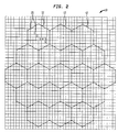
- Figure 2 shows the cells 12 of service area 10 divided into sub-cells 20 represented by the squares formed by the grid lines. The numbers shown represent the sub-cell C 1 , C 2 , C 4 , C 5 , and C 6 respectively.
- Figure 3 shows the hardware architecture for determining the location of a mobile unit 30 in one embodiment.
- Figure 3 illustrates a mobile phone 30, three base stations BS 1 , BS 2 , BS 3 , a mobile switching center 16, a geolocation server 32, and a data base 34.
- the cellular service area 10 is partitioned into cells 12 and then sub-cells C 1 ...C M .
- a set of detectable RF characteristics are defined for each sub-cell, which are referred to as the attributes/properties of the sub-cell.
- the mobile unit 30 measures the RF signals that are associated with the attributes/properties and reports the results to a primary base station BS1 which in turn, reports to the geolocation server 32 illustrated in Figure 3 via the MSC 16.
- the geolocation server 32 statistically compares the measured values with the known attribute values of all sub-cells in a predefined area.
- the sub-cell that has the best matched set of attribute values with the measured values is the one that the mobile unit 30 is repeated to be in.
- the known set of attribute values in database 34 for each sub-cell account statistically for weather conditions, time of day, and other environmental variations that could affect the RF characteristics.
- the comparison is periodically performed and the location of the mobile unit 30 can be determined at any given time. As a result, the problem of geolocation can be solved by pattern recognition.
- S is the area that the mobile unit 30 is known to be in.
- S may be a sector that can be determined by the existing technology where the mobile unit 30 is.
- a 1 is the PN code that identifies a particular base station BS x
- a 2 is the strength of the PN signal
- a 3 is the phase shift.
- a 1 ...A n are random variables.
- D i is the domain of A i which contains all possible values of A i and a j denotes a property which is defined such that the attribute A j has a certain value or a value set that can be used to characterize a sub-cell.
- P(a i ) is the probability of the occurrence of a i over all sub-cells
- C j ) is the probability of the occurrence of a I in C j
- P(C j ) the probability that the mobile unit 30 is in C j independent of properties
- a i ) is the probability the mobile unit 30 is in C j given an observed property of a i .
- the goal of the present invention is to find the highest P(C i
- A*), namely the highest probability that the mobile unit 30 is in C i given a set of measured or observed values A*, where A* ⁇ a 1 , a 2 , a 3 , . . ., a n ⁇ .
- A*) can be obtained using the following Bayes formula: P(C i
- A*) P(C i )P(A*
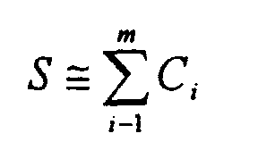
- P(C i ) can be assumed to be 1/m initially, a uniform distribution, since there is no a priori knowledge where the mobile unit 30 might be.
- C s ), S 1, . . ., m and
- C i ) can be obtained using: P (A*
- C i ) P(a 1
- the measurement is taken at time t+ ⁇ t, and P(C i ) is updated with P(C i
- the database 34 for the sub-cells is defined by a set of attributes.
- the database 34 can be implemented as an adjunct server at the MSC 16 or any base station BS 1 ...BS N running any commercially available database management system.
- the database 34 is organized by cells and by sectors to provide efficient searching methods.
- the attribute values may be obtained by a survey of the coverage area and the probability distribution function for A* can be constructed based on the survey results.
- the size of a sub-cell with 125m radius will result in a reasonable size for the database. For example, if the cell has a radius of 25km, the number of sub-cells will be approximately 40,000 in a cell. Hence, there will be 40,000 records per base station which is a relatively small database.
- One way is to use specially designed equipment to survey the service area 10 exhaustively.
- the equipment is used to gather RF characteristics for a location and record the data.
- the data records are then processed to create the database 34.
- This process is automated using a computer program to gather data and create the database 34. This method provides an accurate database.
- the database 34 can also be created by the construction of a statistical model.
- the statistical model is constructed by using an RF propagation formula.
- the parameters in the model are verified by a limited number of observations of the RF characteristics in sample locations in the service area 10. The probability of certain observation can then be calculated and stored in the database 34.
- Figure 4 shows an example of the database 34 that contains the statistical data for C 1 , C 2 , C 3 , C 4 , C 5 , and C6 as in the first column.
- the second column represents the attribute BS 1 and its values
- the third column is the probability denoted by p1 of a particular attribute value could be observed in a sub-cell.
- P(a 1 /C 1 ) has the value 1.
- the numbers 161/232/16 for example, separate by "/" represent the base station ID, the pilot ID, and the average pilot strength for the base station and pilot, respectively.
- the fourth column and fifth column represent the attribute values for BS 2 and their probabilities denoted by p2, and so on for BS 3 and p3.
- the four numbers separated by "/" in the latter cases represent the base station ID, the pilot ID, the chip offset, and the pilot strength, respectively.
- the present invention uses the ratio of the pilot strength stored in the database 34 to the observed pilot strength to define the measure of the closeness between the two values.
- the RF attributes are discrete attributes, such as average pilot strength, chip offset, or pilot strength.
- continuous attributes or features may be utilized, such as signature waveforms.
- the set of attributes may be either replaced or enhanced by the signatures of the measured signal waveforms.
- Other pattern recognition techniques such as fuzzy logic can then be applied to analyze the continuous attributes.
- Utilizing the pattern recognition-based technique or fuzzy logic technique described above may be performed utilizing only one base station or more than one base station.
Landscapes
- Engineering & Computer Science (AREA)
- Physics & Mathematics (AREA)
- General Physics & Mathematics (AREA)
- Radar, Positioning & Navigation (AREA)
- Remote Sensing (AREA)
- Computer Networks & Wireless Communication (AREA)
- Signal Processing (AREA)
- Mobile Radio Communication Systems (AREA)
Abstract
Description
Claims (15)
- A method of identifying a geographical location of a mobile terminal, comprising the steps of:comparing a set of RF characteristics from the mobile terminal with a set of RF attributes for each of a plurality of sub-cells; andidentifying a sub-cell of the plurality of sub-cells whose set of RF attributes most closely match the set of RF characteristics from the mobile terminal as the sub-cell in which the mobile terminal is located.
- A method of identifying a geographical location of a mobile terminal, comprising the steps of:comparing a waveform from the mobile terminal with at least one signature waveform for each of a plurality of sub-cells; andidentifying a sub-cell of the plurality of sub-cells whose at least one signature waveform most closely matches the waveform from the mobile terminal as the sub-cell in which the mobile terminal is located.
- A processor for identifying a geographical location of a mobile terminal, comprising:a comparing unit for comparing a set of RF characteristics from the mobile terminal with a set of RF attributes for each of a plurality of sub-cells; andan identifying unit for identifying a sub-cell of the plurality of sub-cells whose set of RF attributes most closely match the set of RF characteristics from the mobile terminal as the sub-cell in which the mobile terminal is located.
- A processor for identifying a geographical location of a mobile terminal, comprising:a comparing unit for comparing a waveform from the mobile terminal with at least one signature waveform for each of a plurality of sub-cells; andan identifying unit for identifying a sub-cell of the plurality of sub-cells whose at least one signature waveform most closely matches the waveform from the mobile terminal as the sub-cell in which the mobile terminal is located.
- A computer program embodied in a computer-readable medium for identifying a geographical location of a mobile terminal, comprising:a comparing source code segment for comparing a set of RF characteristics from the mobile terminal with a set of RF attributes for each of a plurality of sub-cells; andan identifying source code segment for identifying a sub-cell of the plurality of sub-cells whose set of RF attributes most closely match the set of RF characteristics from the mobile terminal as the sub-cell in which the mobile terminal is located.
- A computer program embodied in a computer-readable medium for identifying a geographical location of a mobile terminal, comprising:
a comparing source code segment for comparing a waveform from the mobile terminal with at least one signature waveform for each of a plurality of sub-cells; and an identifying source code segment for identifying a sub-cell of the plurality of sub-cells whose at least one signature waveform most closely matches the waveform from the mobile terminal as the sub-cell in which the mobile terminal is located. - A computer data signal for identifying a geographical location of a mobile terminal, comprising:
a comparing signal segment for comparing a set of RF characteristics from the mobile terminal with a set of RF attributes for each of a plurality of sub-cells, and an identifying signal segment for identifying a sub-cell of the plurality of sub-cells whose set of RF attributes most closely match the set of RF characteristics from the mobile terminal as the sub-cell in which the mobile terminal is located. - A computer data signal for identifying a geographical location of a mobile terminal, comprising:a comparing signal segment for comparing a waveform from the mobile terminal with at least one signature waveform for each of a plurality of sub-cells; andan identifying signal segment for identifying a sub-cell of the plurality of sub-cells whose at least one signature waveform most closely matches the waveform from the mobile terminal as the sub-cell in which the mobile terminal is located.
- The method of claim I or 2, or the processor of claim 3 or 4, or the embodied program of claim 5 or 6, or the signal of claim 7 or 8, wherein the set of RF attributes, or the at least one signature waveform, for each of the plurality of sub-cells is stored at a mobile system base station or at a mobile switching center.
- The method, or processor, embodied program, or signal of claim 9, wherein only one mobile system base station is required to identify the location of the mobile terminal.
- The method of claim 1 or 2, or the processor of claim 3 or 4, or the program of claim 5 or 6, or the signal of claim 7 or 8, wherein the comparing and identifying steps or units, or segments utilize pattern recognition, or fuzzy logic.
- The method of claim 1, the processor of claim 3, the program of claim 5 or the signal of claim 7, wherein the set of RF attributes for each of the plurality of sub-cells vary based on weather conditions, time of day, and environmental factors.
- The method of claim 1 or 2, or the processor of claim 3 or 4, or the program of claim 5 or 6, or the signal of claim 7 or 8, wherein said comparing and identifying steps or units, or segments repeatedly function over time as the mobile terminal moves.
- The method of claim 1, or the processor of claim 3, or the program of claim 5, or the signal of claim 7, wherein said comparing step or unit, or segment, further comparing the set of RF characteristics from the mobile terminal with the set of RF attributes for each of the plurality of sub-cells and a waveform from the mobile terminal with at least one signature waveform for each of the plurality of sub-cells;
said identifying step unit, or segment, identifying the sub-cell of the plurality of sub-cells whose set of RF attributes and at least one signature waveform most closely match the set of RF characteristics and the waveform from the mobile terminal as the sub-cell in which the mobile terminal is located. - The computer data signal of claim 7 or 8, wherein the computer data signal is embodied in a carrier wave.
Applications Claiming Priority (2)
| Application Number | Priority Date | Filing Date | Title |
|---|---|---|---|
| US139107 | 1998-08-25 | ||
| US09/139,107 US6496701B1 (en) | 1998-08-25 | 1998-08-25 | Pattern-recognition-based geolocation |
Publications (3)
| Publication Number | Publication Date |
|---|---|
| EP0982964A2 true EP0982964A2 (en) | 2000-03-01 |
| EP0982964A3 EP0982964A3 (en) | 2000-03-29 |
| EP0982964B1 EP0982964B1 (en) | 2005-11-16 |
Family
ID=22485163
Family Applications (1)
| Application Number | Title | Priority Date | Filing Date |
|---|---|---|---|
| EP99306468A Expired - Lifetime EP0982964B1 (en) | 1998-08-25 | 1999-08-17 | Pattern recognition-based geolocation |
Country Status (9)
| Country | Link |
|---|---|
| US (1) | US6496701B1 (en) |
| EP (1) | EP0982964B1 (en) |
| JP (1) | JP2000092556A (en) |
| KR (1) | KR100605781B1 (en) |
| CN (1) | CN1255812A (en) |
| AU (1) | AU4466899A (en) |
| BR (1) | BR9903778A (en) |
| CA (1) | CA2275911A1 (en) |
| DE (1) | DE69928333T2 (en) |
Cited By (20)
| Publication number | Priority date | Publication date | Assignee | Title |
|---|---|---|---|---|
| GB2352134A (en) * | 1999-07-01 | 2001-01-17 | Aircom Internat Ltd | Locating mobile telephones |
| WO2002043428A1 (en) * | 2000-11-24 | 2002-05-30 | Telecom Italia S.P.A. | System and method for identifying the position of mobile terminals |
| EP1302783A1 (en) * | 2001-10-10 | 2003-04-16 | Elisa Communications OYJ | Location of a mobile terminal |
| EP1273184A4 (en) * | 2000-03-22 | 2003-05-02 | Polaris Wireless Inc | Location determination using rf fingerprinting |
| WO2004017660A1 (en) * | 2002-07-16 | 2004-02-26 | Siemens Aktiengesellschaft | Method and arrangements for estimating the position of a mobile station in a cellular mobile radio network |
| EP1445970A1 (en) * | 2003-02-05 | 2004-08-11 | Cambridge Positioning Systems Limited | A method and system for locating a mobile radio receiver in a radio system with multiple tranmitters |
| WO2005011321A1 (en) * | 2003-07-19 | 2005-02-03 | Polaris Wireless, Inc. | Location estimation of wireless terminals through pattern matching of deduced and empirical signal-strength measurements |
| WO2006096923A1 (en) * | 2005-03-18 | 2006-09-21 | Seeker Wireless Pty Limited | Enhanced mobile location |
| WO2006096922A1 (en) * | 2005-03-18 | 2006-09-21 | Seeker Wireless Pty Limited | Enhanced mobile location method and system |
| US7176831B2 (en) | 2002-02-15 | 2007-02-13 | Selex Communications Limited | Emitter location system |
| WO2008029137A1 (en) * | 2006-09-07 | 2008-03-13 | Zone Tracker Limited | Location identification system and method for a mobile communications network |
| EP1865740A3 (en) * | 2006-06-09 | 2008-05-28 | Vodafone Holding GmbH | Determining the position of mobile terminals in a mobile telephone network and uses therefor |
| US8244236B2 (en) | 2010-04-29 | 2012-08-14 | Wavemarket, Inc. | System and method for aggregating and disseminating mobile device tag data |
| US8463285B2 (en) | 2005-04-08 | 2013-06-11 | Wavemarket, Inc. | Systems and methods for mobile terminal location determination using profiles of radio signal parameter measurements |
| US8504077B2 (en) | 2010-12-04 | 2013-08-06 | Wavemarket, Inc. | System and method for monitoring and disseminating mobile device location information |
| US8737985B2 (en) | 2007-11-26 | 2014-05-27 | Wavemarket, Inc. | Methods and systems for zone creation and adaption |
| US8787171B2 (en) | 2008-04-07 | 2014-07-22 | Wavemarket, Inc. | Efficient collection of wireless transmitter characteristics |
| US8798613B2 (en) | 2007-09-17 | 2014-08-05 | Wavemarket, Inc. | Systems and method for triggering location based voice and/or data communications to or from mobile ratio terminals |
| US9402155B2 (en) | 2014-03-03 | 2016-07-26 | Location Labs, Inc. | System and method for indicating a state of a geographic area based on mobile device sensor measurements |
| US9438685B2 (en) | 2013-03-15 | 2016-09-06 | Location Labs, Inc. | System and method for display of user relationships corresponding to network-enabled communications |
Families Citing this family (47)
| Publication number | Priority date | Publication date | Assignee | Title |
|---|---|---|---|---|
| US7899467B2 (en) * | 1998-09-22 | 2011-03-01 | Polaris Wireless, Inc. | Estimating the location of a wireless terminal based on the traits of the multipath components of a signal |
| US7257414B2 (en) * | 1998-09-22 | 2007-08-14 | Polaris Wireless, Inc. | Estimating the Location of a Wireless Terminal Based on Non-Uniform Probabilities of Movement |
| US7734298B2 (en) * | 1998-09-22 | 2010-06-08 | Polaris Wireless, Inc. | Estimating the location of a wireless terminal based on signal path impairment |
| EP1056306B1 (en) * | 1999-05-26 | 2006-10-11 | Sony Deutschland GmbH | Geolocation determination |
| US6889053B1 (en) * | 1999-07-26 | 2005-05-03 | Lucent Technologies Inc. | Likelihood-based geolocation prediction algorithms for CDMA systems using pilot strength measurements |
| JP2001103537A (en) * | 1999-07-29 | 2001-04-13 | Ntt Docomo Inc | Location information notification method and device |
| US7127260B1 (en) * | 1999-10-18 | 2006-10-24 | Samsung Electronics Co., Ltd. | Apparatus and method for determining paging alert mode in a mobile communication system |
| CN100544509C (en) | 2000-03-31 | 2009-09-23 | 株式会社Ntt都科摩 | position reporting method and related mobile communication terminal |
| US20020025822A1 (en) * | 2000-08-18 | 2002-02-28 | Hunzinger Jason F. | Resolving ambiguous sector-level location and determining mobile location |
| JP3648140B2 (en) * | 2000-08-21 | 2005-05-18 | 株式会社アドバンテスト | Radio wave monitoring method and apparatus |
| JP3587448B2 (en) * | 2000-09-27 | 2004-11-10 | 株式会社東芝 | Position detection system and position detection method |
| US7039418B2 (en) * | 2000-11-16 | 2006-05-02 | Qualcomm Incorporated | Position determination in a wireless communication system with detection and compensation for repeaters |
| US6871077B2 (en) * | 2001-10-09 | 2005-03-22 | Grayson Wireless | System and method for geolocating a wireless mobile unit from a single base station using repeatable ambiguous measurements |
| JP3972755B2 (en) * | 2002-07-11 | 2007-09-05 | 株式会社日立製作所 | Position measuring method, and terminal device and server used therefor |
| CN100461871C (en) * | 2002-08-16 | 2009-02-11 | 中兴通讯股份有限公司 | A mobile positioning method for improving the accuracy of determining the position of a mobile station |
| US9285453B2 (en) | 2002-08-19 | 2016-03-15 | Q-Track Corporation | Method of near-field electromagnetic ranging and location |
| US7298314B2 (en) | 2002-08-19 | 2007-11-20 | Q-Track Corporation | Near field electromagnetic positioning system and method |
| US8018383B1 (en) | 2010-06-08 | 2011-09-13 | Q-Track Corporation | Method and apparatus for determining location using signals-of-opportunity |
| US7538715B2 (en) * | 2004-10-04 | 2009-05-26 | Q-Track Corporation | Electromagnetic location and display system and method |
| US7414571B2 (en) | 2002-08-19 | 2008-08-19 | Q-Track Corporation | Low frequency asset tag tracking system and method |
| US7433695B2 (en) * | 2002-11-18 | 2008-10-07 | Polaris Wireless, Inc. | Computationally-efficient estimation of the location of a wireless terminal based on pattern matching |
| US7460505B2 (en) * | 2003-02-04 | 2008-12-02 | Polaris Wireless, Inc. | Location estimation of wireless terminals through pattern matching of signal-strength differentials |
| US7346359B2 (en) * | 2003-07-31 | 2008-03-18 | Pango Networks, Inc. | Method for RF fingerprinting |
| US7359718B2 (en) * | 2004-04-30 | 2008-04-15 | Hong Kong Applied Science And Technology Research Institute Co., Ltd. | Location determination and location tracking in wireless networks |
| US7298328B2 (en) * | 2004-12-13 | 2007-11-20 | Jackson Wang | Systems and methods for geographic positioning using radio spectrum signatures |
| US7881905B2 (en) * | 2004-11-17 | 2011-02-01 | Qualcomm Incorporated | Method for ambiguity resolution in location determination |
| US7796983B2 (en) * | 2005-04-27 | 2010-09-14 | The Regents Of The University Of California | Physics-based statistical model and simulation method of RF propagation in urban environments |
| EP1882374A4 (en) * | 2005-05-17 | 2008-05-21 | Andrew Corp | METHOD AND APPARATUS FOR DETERMINING A PROPAGATION WEAKENING |
| EP1941749A4 (en) | 2005-10-24 | 2012-04-18 | Wavemarket Inc D B A Location Labs | Mobile service maintenance management |
| WO2007051223A1 (en) * | 2005-11-04 | 2007-05-10 | Seeker Wireless Pty Limited | Profile based communications service |
| US7753278B2 (en) * | 2006-05-22 | 2010-07-13 | Polaris Wireless, Inc. | Estimating the location of a wireless terminal based on non-uniform locations |
| US8965393B2 (en) * | 2006-05-22 | 2015-02-24 | Polaris Wireless, Inc. | Estimating the location of a wireless terminal based on assisted GPS and pattern matching |
| JP2007316070A (en) * | 2006-05-22 | 2007-12-06 | Polaris Wireless Inc | Prediction method of whereabouts of wireless terminal |
| JP2007316068A (en) * | 2006-05-22 | 2007-12-06 | Polaris Wireless Inc | Method of estimating location of wireless terminal |
| KR100814762B1 (en) * | 2006-11-07 | 2008-03-19 | 에스케이 텔레콤주식회사 | Method and system for providing network based location positioning to mobile communication terminal using G-pCell database |
| US8311018B2 (en) | 2007-02-05 | 2012-11-13 | Andrew Llc | System and method for optimizing location estimate of mobile unit |
| WO2008109948A1 (en) * | 2007-03-13 | 2008-09-18 | Seeker Wireless Pty Limited | Enhanced zone determination |
| SG146461A1 (en) * | 2007-03-15 | 2008-10-30 | Agis Pte Ltd | Location determination using sequential pattern recognition |
| US8725727B2 (en) | 2008-09-24 | 2014-05-13 | Sony Corporation | System and method for determining website popularity by location |
| US9046591B1 (en) * | 2009-05-07 | 2015-06-02 | Sigtem Technology, Inc. | Coordinate-free measurement-domain navigation and guidance using location-dependent radio signal measurements |
| US20110255413A1 (en) * | 2010-04-15 | 2011-10-20 | Mediatek Inc. | Communication Apparatus and ID Packet Recognition Method Thereof |
| US8599011B2 (en) | 2010-07-30 | 2013-12-03 | Q-Track Corporation | Firefighter location and rescue equipment employing path comparison of mobile tags |
| US8514131B2 (en) * | 2010-09-03 | 2013-08-20 | Qualcomm Incorporated | Methods and apparatus for increasing the reliability of signal reference maps for use in position determination |
| KR101160766B1 (en) * | 2010-09-13 | 2012-06-28 | 인하대학교 산학협력단 | Fuzzy logic-based location prediction system using inference and method therefor |
| US8526968B2 (en) | 2011-02-14 | 2013-09-03 | Andrew Llc | System and method for mobile location by dynamic clustering |
| US9125067B2 (en) | 2012-02-03 | 2015-09-01 | Commscope Technologies Llc | System and method for mobile location using ranked parameter labels |
| CN107454565B (en) | 2016-05-31 | 2019-10-18 | 大唐移动通信设备有限公司 | A kind of localization method and device |
Family Cites Families (13)
| Publication number | Priority date | Publication date | Assignee | Title |
|---|---|---|---|---|
| GB9016277D0 (en) | 1990-07-25 | 1990-09-12 | British Telecomm | Location and handover in mobile radio systems |
| SE9302140L (en) | 1993-06-21 | 1994-08-29 | Televerket | Procedure for locating mobile stations in digital telecommunications networks |
| GB2291300B (en) | 1994-06-20 | 1997-12-17 | Motorola Ltd | Communications system |
| US5602903A (en) * | 1994-09-28 | 1997-02-11 | Us West Technologies, Inc. | Positioning system and method |
| JPH08107583A (en) * | 1994-10-05 | 1996-04-23 | Nippon Telegr & Teleph Corp <Ntt> | Mobile station position detecting method, system and device for mobile communication |
| US5950124A (en) * | 1995-09-06 | 1999-09-07 | Telxon Corporation | Cellular communication system with dynamically modified data transmission parameters |
| US5844522A (en) * | 1995-10-13 | 1998-12-01 | Trackmobile, Inc. | Mobile telephone location system and method |
| JP2776784B2 (en) * | 1995-12-27 | 1998-07-16 | 日本電気移動通信株式会社 | Moving object position detection system |
| US6064339A (en) * | 1997-01-08 | 2000-05-16 | Us Wireless Corporation | Subspace signature matching for location ambiguity resolution in wireless communication systems |
| US6026304A (en) * | 1997-01-08 | 2000-02-15 | U.S. Wireless Corporation | Radio transmitter location finding for wireless communication network services and management |
| US6108557A (en) * | 1997-01-08 | 2000-08-22 | Us Wireless Corporation | Signature matching for location determination in wireless communication systems |
| US6084546A (en) * | 1997-01-08 | 2000-07-04 | Us Wireless Corporation | Location determination in wireless communication systems using velocity information |
| US6104344A (en) * | 1999-03-24 | 2000-08-15 | Us Wireless Corporation | Efficient storage and fast matching of wireless spatial signatures |
-
1998
- 1998-08-25 US US09/139,107 patent/US6496701B1/en not_active Expired - Lifetime
-
1999
- 1999-06-22 CA CA002275911A patent/CA2275911A1/en not_active Abandoned
- 1999-08-17 DE DE69928333T patent/DE69928333T2/en not_active Expired - Lifetime
- 1999-08-17 EP EP99306468A patent/EP0982964B1/en not_active Expired - Lifetime
- 1999-08-17 BR BR9903778-5A patent/BR9903778A/en not_active Application Discontinuation
- 1999-08-23 AU AU44668/99A patent/AU4466899A/en not_active Abandoned
- 1999-08-24 CN CN99118134.4A patent/CN1255812A/en active Pending
- 1999-08-24 KR KR1019990035157A patent/KR100605781B1/en not_active Expired - Fee Related
- 1999-08-25 JP JP11237679A patent/JP2000092556A/en active Pending
Cited By (31)
| Publication number | Priority date | Publication date | Assignee | Title |
|---|---|---|---|---|
| US7167714B2 (en) | 1998-09-22 | 2007-01-23 | Polaris Wireless, Inc. | Location determination using RF fingerprints |
| US7725111B2 (en) | 1998-09-22 | 2010-05-25 | Polaris Wireless, Inc. | Location determination using RF fingerprinting |
| US6782265B2 (en) | 1998-09-22 | 2004-08-24 | Polaris Wireless, Inc. | Location determination using RF fingerprinting |
| US8068855B2 (en) | 1998-09-22 | 2011-11-29 | Polaris Wireless, Inc. | Location determination using RF fingerprinting |
| GB2352134A (en) * | 1999-07-01 | 2001-01-17 | Aircom Internat Ltd | Locating mobile telephones |
| EP1273184A4 (en) * | 2000-03-22 | 2003-05-02 | Polaris Wireless Inc | Location determination using rf fingerprinting |
| WO2002043428A1 (en) * | 2000-11-24 | 2002-05-30 | Telecom Italia S.P.A. | System and method for identifying the position of mobile terminals |
| US7333816B2 (en) | 2000-11-24 | 2008-02-19 | Telecom Italia S.P.A. | System and method for identifying the position of mobile terminals |
| EP1302783A1 (en) * | 2001-10-10 | 2003-04-16 | Elisa Communications OYJ | Location of a mobile terminal |
| US7176831B2 (en) | 2002-02-15 | 2007-02-13 | Selex Communications Limited | Emitter location system |
| WO2004017660A1 (en) * | 2002-07-16 | 2004-02-26 | Siemens Aktiengesellschaft | Method and arrangements for estimating the position of a mobile station in a cellular mobile radio network |
| WO2004071120A1 (en) * | 2003-02-05 | 2004-08-19 | Cambridge Positioning Systems Limited | A method and system for locating a mobile radio receiver in a radio system with multiple transmitters |
| US8630656B2 (en) | 2003-02-05 | 2014-01-14 | Cambridge Positioning Systems Limited | Method and system for locating a mobile radio receiver in a radio system with multiple transmitters |
| EP1445970A1 (en) * | 2003-02-05 | 2004-08-11 | Cambridge Positioning Systems Limited | A method and system for locating a mobile radio receiver in a radio system with multiple tranmitters |
| WO2005011321A1 (en) * | 2003-07-19 | 2005-02-03 | Polaris Wireless, Inc. | Location estimation of wireless terminals through pattern matching of deduced and empirical signal-strength measurements |
| WO2006096922A1 (en) * | 2005-03-18 | 2006-09-21 | Seeker Wireless Pty Limited | Enhanced mobile location method and system |
| US8355737B2 (en) | 2005-03-18 | 2013-01-15 | Wavemarket, Inc. | Enhanced mobile location |
| WO2006096923A1 (en) * | 2005-03-18 | 2006-09-21 | Seeker Wireless Pty Limited | Enhanced mobile location |
| US8463285B2 (en) | 2005-04-08 | 2013-06-11 | Wavemarket, Inc. | Systems and methods for mobile terminal location determination using profiles of radio signal parameter measurements |
| US8700069B2 (en) | 2005-04-08 | 2014-04-15 | Wavemarket, Inc. | Systems and methods for mobile terminal location determination using radio signal parameter measurements |
| EP1865740A3 (en) * | 2006-06-09 | 2008-05-28 | Vodafone Holding GmbH | Determining the position of mobile terminals in a mobile telephone network and uses therefor |
| EP2262331A3 (en) * | 2006-06-09 | 2011-03-09 | Vodafone Holding GmbH | Determining the position of mobile terminals in a mobile telephone network and uses therefor |
| WO2008029137A1 (en) * | 2006-09-07 | 2008-03-13 | Zone Tracker Limited | Location identification system and method for a mobile communications network |
| US8798613B2 (en) | 2007-09-17 | 2014-08-05 | Wavemarket, Inc. | Systems and method for triggering location based voice and/or data communications to or from mobile ratio terminals |
| US8737985B2 (en) | 2007-11-26 | 2014-05-27 | Wavemarket, Inc. | Methods and systems for zone creation and adaption |
| US8787171B2 (en) | 2008-04-07 | 2014-07-22 | Wavemarket, Inc. | Efficient collection of wireless transmitter characteristics |
| US8457626B2 (en) | 2010-04-29 | 2013-06-04 | Wavemarket, Inc. | System and method for aggregating and disseminating mobile device tag data |
| US8244236B2 (en) | 2010-04-29 | 2012-08-14 | Wavemarket, Inc. | System and method for aggregating and disseminating mobile device tag data |
| US8504077B2 (en) | 2010-12-04 | 2013-08-06 | Wavemarket, Inc. | System and method for monitoring and disseminating mobile device location information |
| US9438685B2 (en) | 2013-03-15 | 2016-09-06 | Location Labs, Inc. | System and method for display of user relationships corresponding to network-enabled communications |
| US9402155B2 (en) | 2014-03-03 | 2016-07-26 | Location Labs, Inc. | System and method for indicating a state of a geographic area based on mobile device sensor measurements |
Also Published As
| Publication number | Publication date |
|---|---|
| AU4466899A (en) | 2000-03-09 |
| CN1255812A (en) | 2000-06-07 |
| KR20000017489A (en) | 2000-03-25 |
| DE69928333D1 (en) | 2005-12-22 |
| JP2000092556A (en) | 2000-03-31 |
| US6496701B1 (en) | 2002-12-17 |
| BR9903778A (en) | 2000-09-05 |
| EP0982964A3 (en) | 2000-03-29 |
| CA2275911A1 (en) | 2000-02-25 |
| KR100605781B1 (en) | 2006-07-31 |
| DE69928333T2 (en) | 2006-06-29 |
| EP0982964B1 (en) | 2005-11-16 |
Similar Documents
| Publication | Publication Date | Title |
|---|---|---|
| US6496701B1 (en) | Pattern-recognition-based geolocation | |
| US6263208B1 (en) | Geolocation estimation method for CDMA terminals based on pilot strength measurements | |
| EP2118810B1 (en) | System and method for optimizing location estimate of mobile unit | |
| US8331953B2 (en) | System and method for estimating the location of a mobile device | |
| US6871077B2 (en) | System and method for geolocating a wireless mobile unit from a single base station using repeatable ambiguous measurements | |
| EP2580605B1 (en) | Methods of and systems for measuring beacon stability of wireless access points | |
| US9052378B2 (en) | Estimation of position using WLAN access point radio propagation characteristics in a WLAN positioning system | |
| EP1197114B1 (en) | Selection of location measurement units for determining the position of a mobile communication station | |
| KR100441068B1 (en) | Method and system for creating a rf signature for a signature region in a wireless communication system | |
| US6259924B1 (en) | Method and system for comparing measured radio frequency signal propagation characteristics in a wireless communication system | |
| Lakmali et al. | Database correlation for GSM location in outdoor & indoor environments | |
| Kuo et al. | Cluster-enhanced techniques for pattern-matching localization systems | |
| Aomumpai et al. | Optimal placement of reference nodes for wireless indoor positioning systems | |
| EP2239671B1 (en) | System and method for associating communication terminals to users based on spatial correlation | |
| Saha et al. | A novel clustering strategy for fingerprinting-based localization system to reduce the searching time | |
| CN102638833B (en) | Method and equipment for neighbor optimization | |
| Lakmali et al. | Design, implementation & testing of positioning techniques in mobile networks | |
| Zhang et al. | On accuracy of region based localization algorithms for wireless sensor networks | |
| Takenga et al. | Robust positioning system based on fingerprint approach | |
| Lyu et al. | Urban area GNSS in‐car‐jammer localization based on pattern recognition | |
| Pereira et al. | Evaluating location fingerprinting methods for underground GSM networks deployed over Leaky Feeder | |
| Jones et al. | Scalable, Occlusion-Aware Geolocation of Ground-Based GNSS Jammers with Networked Smartphones | |
| CN111917494B (en) | Black broadcast signal monitoring and positioning method and system | |
| CN112637768B (en) | Mobile terminal positioning method and device based on cellular network | |
| Promnoi et al. | Road traffic estimation with signal matching in mobile phone using large-size database |
Legal Events
| Date | Code | Title | Description |
|---|---|---|---|
| PUAI | Public reference made under article 153(3) epc to a published international application that has entered the european phase |
Free format text: ORIGINAL CODE: 0009012 |
|
| PUAL | Search report despatched |
Free format text: ORIGINAL CODE: 0009013 |
|
| AK | Designated contracting states |
Kind code of ref document: A2 Designated state(s): DE FI FR GB SE |
|
| AX | Request for extension of the european patent |
Free format text: AL;LT;LV;MK;RO;SI |
|
| AK | Designated contracting states |
Kind code of ref document: A3 Designated state(s): AT BE CH CY DE DK ES FI FR GB GR IE IT LI LU MC NL PT SE |
|
| AX | Request for extension of the european patent |
Free format text: AL;LT;LV;MK;RO;SI |
|
| 17P | Request for examination filed |
Effective date: 20000915 |
|
| AKX | Designation fees paid |
Free format text: DE FI FR GB SE |
|
| 17Q | First examination report despatched |
Effective date: 20040506 |
|
| GRAP | Despatch of communication of intention to grant a patent |
Free format text: ORIGINAL CODE: EPIDOSNIGR1 |
|
| GRAS | Grant fee paid |
Free format text: ORIGINAL CODE: EPIDOSNIGR3 |
|
| GRAA | (expected) grant |
Free format text: ORIGINAL CODE: 0009210 |
|
| AK | Designated contracting states |
Kind code of ref document: B1 Designated state(s): DE FI FR GB SE |
|
| REG | Reference to a national code |
Ref country code: GB Ref legal event code: FG4D |
|
| REF | Corresponds to: |
Ref document number: 69928333 Country of ref document: DE Date of ref document: 20051222 Kind code of ref document: P |
|
| PG25 | Lapsed in a contracting state [announced via postgrant information from national office to epo] |
Ref country code: SE Free format text: LAPSE BECAUSE OF FAILURE TO SUBMIT A TRANSLATION OF THE DESCRIPTION OR TO PAY THE FEE WITHIN THE PRESCRIBED TIME-LIMIT Effective date: 20060216 |
|
| ET | Fr: translation filed | ||
| PLBE | No opposition filed within time limit |
Free format text: ORIGINAL CODE: 0009261 |
|
| STAA | Information on the status of an ep patent application or granted ep patent |
Free format text: STATUS: NO OPPOSITION FILED WITHIN TIME LIMIT |
|
| 26N | No opposition filed |
Effective date: 20060817 |
|
| REG | Reference to a national code |
Ref country code: GB Ref legal event code: 732E Free format text: REGISTERED BETWEEN 20131031 AND 20131106 |
|
| REG | Reference to a national code |
Ref country code: FR Ref legal event code: CD Owner name: ALCATEL-LUCENT USA INC. Effective date: 20131122 |
|
| REG | Reference to a national code |
Ref country code: FR Ref legal event code: GC Effective date: 20140410 |
|
| REG | Reference to a national code |
Ref country code: FR Ref legal event code: RG Effective date: 20141015 |
|
| REG | Reference to a national code |
Ref country code: FR Ref legal event code: PLFP Year of fee payment: 17 |
|
| REG | Reference to a national code |
Ref country code: FR Ref legal event code: PLFP Year of fee payment: 18 |
|
| REG | Reference to a national code |
Ref country code: FR Ref legal event code: PLFP Year of fee payment: 19 |
|
| REG | Reference to a national code |
Ref country code: FR Ref legal event code: PLFP Year of fee payment: 20 |
|
| PGFP | Annual fee paid to national office [announced via postgrant information from national office to epo] |
Ref country code: DE Payment date: 20180823 Year of fee payment: 20 Ref country code: FR Payment date: 20180827 Year of fee payment: 20 |
|
| PGFP | Annual fee paid to national office [announced via postgrant information from national office to epo] |
Ref country code: GB Payment date: 20180822 Year of fee payment: 20 Ref country code: FI Payment date: 20180822 Year of fee payment: 20 |
|
| REG | Reference to a national code |
Ref country code: DE Ref legal event code: R071 Ref document number: 69928333 Country of ref document: DE |
|
| REG | Reference to a national code |
Ref country code: GB Ref legal event code: PE20 Expiry date: 20190816 |
|
| PG25 | Lapsed in a contracting state [announced via postgrant information from national office to epo] |
Ref country code: GB Free format text: LAPSE BECAUSE OF EXPIRATION OF PROTECTION Effective date: 20190816 |