EP0985558B1 - Bandage pneumatique pour roulage à plat - Google Patents
Bandage pneumatique pour roulage à plat Download PDFInfo
- Publication number
- EP0985558B1 EP0985558B1 EP19990307078 EP99307078A EP0985558B1 EP 0985558 B1 EP0985558 B1 EP 0985558B1 EP 19990307078 EP19990307078 EP 19990307078 EP 99307078 A EP99307078 A EP 99307078A EP 0985558 B1 EP0985558 B1 EP 0985558B1
- Authority
- EP
- European Patent Office
- Prior art keywords
- radially
- ply
- tyre
- sidewall
- outside
- Prior art date
- Legal status (The legal status is an assumption and is not a legal conclusion. Google has not performed a legal analysis and makes no representation as to the accuracy of the status listed.)
- Expired - Lifetime
Links
Images

Classifications
-
- B—PERFORMING OPERATIONS; TRANSPORTING
- B60—VEHICLES IN GENERAL
- B60C—VEHICLE TYRES; TYRE INFLATION; TYRE CHANGING; CONNECTING VALVES TO INFLATABLE ELASTIC BODIES IN GENERAL; DEVICES OR ARRANGEMENTS RELATED TO TYRES
- B60C15/00—Tyre beads, e.g. ply turn-up or overlap
- B60C15/0009—Tyre beads, e.g. ply turn-up or overlap features of the carcass terminal portion
- B60C15/0036—Tyre beads, e.g. ply turn-up or overlap features of the carcass terminal portion with high ply turn-up, i.e. folded around the bead core and terminating radially above the point of maximum section width
- B60C15/0045—Tyre beads, e.g. ply turn-up or overlap features of the carcass terminal portion with high ply turn-up, i.e. folded around the bead core and terminating radially above the point of maximum section width with ply turn-up up to the belt edges, i.e. folded around the bead core and extending to the belt edges
-
- B—PERFORMING OPERATIONS; TRANSPORTING
- B60—VEHICLES IN GENERAL
- B60C—VEHICLE TYRES; TYRE INFLATION; TYRE CHANGING; CONNECTING VALVES TO INFLATABLE ELASTIC BODIES IN GENERAL; DEVICES OR ARRANGEMENTS RELATED TO TYRES
- B60C15/00—Tyre beads, e.g. ply turn-up or overlap
- B60C15/06—Flipper strips, fillers, or chafing strips and reinforcing layers for the construction of the bead
- B60C15/0603—Flipper strips, fillers, or chafing strips and reinforcing layers for the construction of the bead characterised by features of the bead filler or apex
- B60C15/0607—Flipper strips, fillers, or chafing strips and reinforcing layers for the construction of the bead characterised by features of the bead filler or apex comprising several parts, e.g. made of different rubbers
-
- B—PERFORMING OPERATIONS; TRANSPORTING
- B60—VEHICLES IN GENERAL
- B60C—VEHICLE TYRES; TYRE INFLATION; TYRE CHANGING; CONNECTING VALVES TO INFLATABLE ELASTIC BODIES IN GENERAL; DEVICES OR ARRANGEMENTS RELATED TO TYRES
- B60C17/00—Tyres characterised by means enabling restricted operation in damaged or deflated condition; Accessories therefor
- B60C17/0009—Tyres characterised by means enabling restricted operation in damaged or deflated condition; Accessories therefor comprising sidewall rubber inserts, e.g. crescent shaped inserts
Definitions
- the present invention relates to a pneumatic tyre, more particularly to a run-flat tyre having an improved sidewall reinforcing structure.
- a tyre which has a sidewall portion (s) reinforced with a relatively thick rubber layer (g) has been proposed, wherein this thick rubber layer (g) is disposed on the axially inside of the carcass to extend along the inside of the tyre.
- GB-A-2 087 805 discloses a pneumatic safety tyre having a carcass comprising an inner and outer ply each of organic fibre cords and having turned-up portions from inside to the outside of the tyre and sidewall reinforcing rubber layers including an inside layer axially inside the main portion of the inner ply, a middle layer between the main portion of the inner ply and the main portion of the outer ply and an outside layer outside the main portion of the outer ply.
- At least one of the sidewall reinforcing rubber layers having a radially outer end located beneath the belt and at least one of the sidewall rubber layers having a radially inner end located radially outward of the bead core but inwards of the maximum tyre section width point, at the maximum tyre section width print, the total of the thickness of the inside layer, the thickness of the middle layer , and the thickness of the outside layer being not less than 0.5 times the thickness of the sidewall portion.
- EP-A-0 924 867 which was published on 12.06.2002 also proposes sidewall inserts between carcass plies which may have turn-ups extending to edges between the belt and the carcass main portion.
- an object of the present invention to provide a run-flat tyre improved in run-flat performance, e.g. running distance, durability and the like without increasing the tyre weight and deteriorating running performance under normal conditions by means of improving the shoulder portions of the tyre.
- the present invention is a run-flat tyre as set out in claim 1.
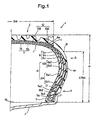
- the run-flat tyre 1 comprises a tread portion 2, a pair of sidewall portions 3, a pair of bead portions 4 each with a bead core 5 therein, a radial ply carcass 6, a belt 7, 10 disposed radially outside the carcass 6 in the tread portion 2, and sidewall reinforcing layers 9 disposed in each of the sidewall portions 3.
- the tyre 1 is mounted on its standard wheel rim J and inflated to standard inner pressure but loaded with no tyre load.
- the sizes or dimensions of the tyre are measured under this condition if not specifically mentioned.
- the standard rim is the "standard rim” specified in JATMA, the “Measuring Rim” in ETRTO, the “Design Rim” in TRA or the like.
- the standard pressure is the "maximum air pressure" in JATMA, the “Inflation Pressure” in ETRTO, the maximum pressure given in the "Tyre Load Limits at Various Cold Inflation Pressures" table in TRA or the like.
- the standard load is the "maximum load capacity" in JATMA, the “Load Capacity” in ETRTO, the maximum value given in the above-mentioned table in TRA or the like.
- the standard pressure 180 kPa is used.
- the carcass 6 comprises an inner ply 6A and an outer ply 6B each made of organic fibre cords.
- organic fibre cords rayon cords are used in this embodiment, but other materials such as polyester, nylon and the like can be used.
- the cords of each carcass ply are arranged radially at an angle of 75 to 90 degrees with respect to the tyre equator C so that the ply has a radial structure.
- the cord angle in each ply is the same value of about 88 degrees but the inclining directions are opposite with respect to the tyre equator C.
- the cords of one ply cross those of the other ply at a small angle of about 4 degrees in this example.
- the belt includes a breaker 7 and a band or bandage 10 disposed radially outside the breaker 7.
- the breaker 7 comprises two crossed plies 7A and 7B, each ply made of parallel cords laid at an angle of from 10 to 35 degrees with respect to the tyre equator C.
- each ply is made of aramid cords laid at 22 degrees. Aside from aramid cords, steel cords and the like can be used.
- the band 10 is made of an organic fibre cord laid substantially parallel to the tyre circumferential direction.
- the band cords have a lower elastic modulus than the breaker cords.
- the band 10 is composed of a pair of axially spaced edge-band plies 10A covering the axial edges of the breaker 7 and a full-width band ply 10B disposed radially outside thereof and extending across the substantially full width of the breaker 7.
- each edge-band ply 10A has a width of about 10 to 20 % (in this example about 16%) of the axial width 3W of the breaker 7.
- Both the band plies 10A and 10B in this embodiment are formed by spirally winding a tape of rubber, in which parallel nylon cords are embedded along the length thereof.
- the above-mentioned carcass plies 6A and 6B extend between the bead portions through the tread portion and sidewall portions and are turned up around the bead core 5 in each bead portion from the inside to the outside of the tyre so that: the carcass ply 6A comprises a pair of turnup portions 6b1 and a main portion 6a1 therebetween; and the carcass ply 6B comprises a pair of turnup portions 6b2 and a main portion 6a2 therebetween.
- edges 6e of the turnup portions 6b1 of the inner ply 6A extend to between the carcass 6 and breaker 7, and the overlap 11 of the turnup portion 6b1 with the breaker 7 has an axial length L of from 3 to 8 % (in this embodiment about 6.5%) of the axial width BW of the breaker.
- the turnup portion 6b2 of the outer ply 6B has a height of about 0.4 to 0.6 times the tyre section height H (in this embodiment about 0.46 times) each from the bead base line BL. This means that the turnup end is positioned around the maximum tyre section width point M.
- the tyre section height H is the radial height measured from the bead base line BL to the radially outermost point.
- the bead base line is an axial line passing to a position corresponding to the rim diameter.
- a bead apex 12 is disposed between the turnup portion 6b2 and main portion 6a2 of the outer carcass ply 6B.
- the bead apex 12 is made of a hard rubber and extends and tapers radially outwardly from the outside 5a of the bead core 5.
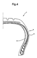
- the above-mentioned sidewall reinforcing layers 9 include: an inside reinforcing rubber layer 9a disposed between the main portion 6a1 of the inner ply 6A and an air tight inner liner (i) disposed along the inside of the tyre; a middle reinforcing rubber layer 9b disposed between the main portions 6a1 and 6a2 of the inner and outer plies 6A and 6B; and an outside reinforcing rubber layer 9c disposed between the main portion 6a2 of the outer ply 6B and the turnup portions 6b1 and 6b2.
- Each of the reinforcing rubber layers 9a-9c tapers radially inwardly and radially outwardly.
- each layer (9a, 9b, 9c) has a radially outer end (9a1, 9b1, 9c1) located beneath, i.e. radially inwards of, the breaker 7 as shown in Fig.2, and a radially inner end (9a2, 9b2, 9c2) located radically inside the maximum tyre section width point M but radially outside the outer end 5a of the bead core 5.
- the outer ends 9a1, 9b1 and 9c1 are placed at different axial positions so that the total thickness of the layers gradually changes from the tread portion 2 to the sidewall portion 3.
- the outer end 9a1 is inmost, and the outer end 9c1 is outmost.
- the outer end 9b1 is in the middle of the others.
- At least one of the radially inner ends 9a2, 9b2 and 9c2 of the reinforcing rubber layers 9a, 9b and 9c is positioned radially inwards of the maximum tyre section width point M. None of the radially inner ends 9a2, 9b2 and 9c2 is positioned radially inwards of the outer end 5a of the bead core 5.
- the radially inner tapered portion of the outside layer 9c and the radially outer tapered portion of the bead apex 12 are spliced, and in this spliced portion, the outside layer 9c is positioned axially outside the bead apex 12 and the radially inner end 9c2 thereof reaches near the radially outside of the bead core 5.
- the radially inner ends 9b2 and 9a2 of the middle and inside layers 9b and 9a reach to radially different positions which are radially inwards of the radially outer end of the bead apex 12 but radially outwards of the radially out end 5a of the bead core 5.
- the total thickness of the sidewall portion 3 is such that the total thickness S2 at a point B is set in the range of from 1.0 to 1.4 times, preferably more than 1.0 times but not more than 1.4 times, more preferably more than 1.0 times but not more than 1.2 times, still more preferably 1.1 to 1.2 times the total thickness S1 at the maximum tyre section width point M.
- the point B is a point on the outer surface of the tyre at a radial height of 75 % of the tyre section height H.
- the total thickness S1, S2 is measured along the normal direction to the outer surface or profile of the tyre.
- the total (a1+b1+c1) of the thicknesses a1, b1 and c1 of the layers 9a, 9b and 9c, respectively, is set to be not less than 50 %, preferably 50 to 70 %, more preferably 50 to 65 %, still more preferably 55 to 65 % of the total thickness S1.
- the total (a2+b2+c2) of the thicknesses a2, b2 and c2 of the layers 9a, 9b and 9c, respectively, is set to be not less than 40 %, preferably 45 to 60 % of the total thickness S2.
- the total (a2+b2+c2) is smaller than the total (a1+b1+c1).
- Each of the reinforcing rubber layers 9 is made of a rubber compound of low-heat-generation having a complex elastic modulus E* of from 7.0 to 12.0 MPa and a loss tangent (tan ⁇ ) of not more than 0.02, preferably not more than 0.01, more preferably in the range of from 0.008 to 0.001.
- all the layers 9a, 9b and 9c are made of the same rubber compound, but it is also possible to use different rubber compounds which satisfy
- the complex elastic modulus E* is outside the range of from 7.0 to 12.0 MPa, the bending rigidity of the sidewall portion 3 tends to decrease and heat generation increases and ride comfort deteriorates.
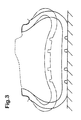
- Example tyres were remarkably increased in runable distance although the tyre weight was maintained at the same level as the Prior Art tyre.
- Fig.3 shows cross-sections of the Embodiment tyre when loaded with 4.41 kN under normally inflated condition (solid line) and a flat condition (chain line). This shows that even when the tyre is punctured the Embodiment tyre can endure its load without parts of the inner surfaces touching. Tyre Prior Ex.1 Ex.2 Ref.
Landscapes
- Engineering & Computer Science (AREA)
- Mechanical Engineering (AREA)
- Tires In General (AREA)
Claims (4)
- Pneu à flancs renforcés comprenant une partie de bande de roulement (2), une paire de parties de paroi latérale (3), une paire de parties de talon (4) chacune avec une tringle (5) à l'intérieur de celle-ci, une carcasse (6) comprenant un pli interne (6A) et un pli externe (6B) chacun réalisé à partir de cordes de fibre organique, une ceinture (7) disposée de manière radiale à l'extérieur de la carcasse (6) dans la partie de bande de roulement (2), des couches de caoutchouc de renforcement (9) de la paroi latérale disposées dans chacune de ladite partie de paroi latérale (3), chacun du pli interne (6A) et du pli externe (6B) s'étendant entre les parties de talon (4) à travers la partie de bande de roulement (2) et des parties de paroi latérale (3) et retourné autour de la tringle (5) dans chacune de ladite partie de talon (4) de l'intérieur vers l'extérieur du pneu pour former une paire de parties retournées (6b1, 6b2) et une partie principale (6a1, 6a2) entre elles, les parties retournées du pli interne étendu à l'intérieur entre la ceinture (7) et la carcasse (6) et chacune ayant une extrémité (6e) radialement externe fixée entre elles, lesdites couches de caoutchouc de renforcement (9) de paroi latérale comprenant une couche intérieure (9a) disposée à l'intérieur de manière axiale de la partie principale (6a2) du pli interne (6A) ; une couche centrale (9b) disposée entre la partie principale (6a1) du pli interne et de la partie principale (6a2) du pli externe (6B) ; et une couche externe (9c) disposée de manière axiale à l'extérieur de la partie principale du pli externe (6a2), au moins l'une des couches de caoutchouc de renforcement (9a, 9b, 9c) de la paroi latérale ayant une extrémité radialement externe (9a1, 9b1, 9c1) située au dessous de la ceinture (7), au moins l'une des couches de caoutchouc de renforcement (9a, 9b, 9c) de la paroi latérale ayant une extrémité radialement interne (9a2, 9b2, 9c2) située de manière radiale vers l'extérieur de la tringle (5) mais de manière radiale vers l'intérieur d'un point (M) en largeur de la section du pneu maximum, au point en largeur de la section du pneu maximum, le total (a1 + b1 + c1) de l'épaisseur (a1) de la couche intérieure (9a), de l'épaisseur (b1) de la couche centrale (b), et de l'épaisseur (c1) de la couche externe (9c) étant supérieur à 0,5 fois l'épaisseur (S1) de la partie de paroi latérale et une épaisseur (S2) de la partie de paroi latérale (3) à un point situé à 75% de la hauteur de la section du pneu, est de 1,0 à 1,2 fois l'épaisseur (S1) de la partie de paroi latérale au point en largeur de la section du pneu maximum.
- Pneu à flancs renforcés selon la revendication 1, caractérisé en ce que le total des épaisseurs (a2, b2, c2) de la couche interne, de la couche centrale et de la couche externe est supérieur à 40% de l'épaisseur (S2) de la partie de paroi latérale à un point situé à 75% de la hauteur de la section du pneu.
- Pneu à flancs renforcés selon la revendication 1 ou 2, caractérisé en ce que les extrémités radialement externes (9a1, 9b1, 9c1) des couches intérieure, centrale et extérieure (9a, 9b, 9c) sont disposées dans une région située au dessous de la ceinture de la nappe de renforcement de la bande de roulement (7).
- Pneu à flancs renforcés selon l'une quelconque des revendications 1 à 3, caractérisé en ce que les extrémités radialement internes (9a2, 9b2, 9c2) des couches intérieure, centrale et extérieure (9a, 9b, 9c) sont disposées dans une région radialement vers l'intérieur du point (M) en largeur de la section du pneu maximum, mais radialement vers l'extérieur de l'extrémité radialement externe de la tringle (5).
Applications Claiming Priority (2)
| Application Number | Priority Date | Filing Date | Title |
|---|---|---|---|
| JP25424398 | 1998-09-08 | ||
| JP25424398A JP3007882B1 (ja) | 1998-09-08 | 1998-09-08 | ランフラットタイヤ |
Publications (3)
| Publication Number | Publication Date |
|---|---|
| EP0985558A2 EP0985558A2 (fr) | 2000-03-15 |
| EP0985558A3 EP0985558A3 (fr) | 2001-05-16 |
| EP0985558B1 true EP0985558B1 (fr) | 2004-04-14 |
Family
ID=17262275
Family Applications (1)
| Application Number | Title | Priority Date | Filing Date |
|---|---|---|---|
| EP19990307078 Expired - Lifetime EP0985558B1 (fr) | 1998-09-08 | 1999-09-07 | Bandage pneumatique pour roulage à plat |
Country Status (4)
| Country | Link |
|---|---|
| US (1) | US6196289B1 (fr) |
| EP (1) | EP0985558B1 (fr) |
| JP (1) | JP3007882B1 (fr) |
| DE (1) | DE69916386T2 (fr) |
Families Citing this family (20)
| Publication number | Priority date | Publication date | Assignee | Title |
|---|---|---|---|---|
| DE19860362A1 (de) * | 1998-12-24 | 2000-06-29 | Dunlop Gmbh | Fahrzeugluftreifen |
| US6332487B1 (en) * | 1999-05-06 | 2001-12-25 | Dunlop Tire Corporation | Tire with carcass cord angle in crown region different than in sidewall region |
| US6834696B1 (en) | 2000-06-29 | 2004-12-28 | Bridgestone/Firestone North American Tire, Llc | Runflat tire with cantilever-like sidewall construction |
| JP4053719B2 (ja) | 2000-09-08 | 2008-02-27 | 住友ゴム工業株式会社 | ランフラット性を向上したタイヤ |
| US6719029B2 (en) * | 2002-08-09 | 2004-04-13 | The Goodyear Tire & Rubber Company | Tire wall gauges to optimize runflat tire ride comfort |
| JP4170821B2 (ja) * | 2003-05-30 | 2008-10-22 | 住友ゴム工業株式会社 | 空気入りラジアルタイヤ |
| US7546862B2 (en) * | 2005-05-06 | 2009-06-16 | New Tech Tire Llc | Non-pneumatic vehicle tire |
| FR2864469A1 (fr) * | 2003-12-30 | 2005-07-01 | Michelin Soc Tech | Pneumatique a flancs autoporteurs asymetriques |
| DE602004012380T2 (de) * | 2004-02-17 | 2009-03-12 | Sumitomo Rubber Industries Ltd., Kobe | Seitenverstärkende Gummizusammensetzung und daraus hergestellter Notlaufreifen |
| JP3977817B2 (ja) * | 2004-03-16 | 2007-09-19 | 住友ゴム工業株式会社 | ランフラットタイヤ |
| JP4653556B2 (ja) * | 2005-05-13 | 2011-03-16 | 住友ゴム工業株式会社 | ランフラットタイヤ及びそれを用いた車両 |
| KR101472597B1 (ko) * | 2008-08-07 | 2014-12-15 | 스미도모 고무 고교 가부시기가이샤 | 타이어 |
| US8672006B2 (en) | 2011-07-15 | 2014-03-18 | New Tech Tire Llc | Non-pneumatic tire |
| JP6295133B2 (ja) | 2014-04-24 | 2018-03-14 | 東洋ゴム工業株式会社 | ランフラットタイヤ |
| JP6324815B2 (ja) | 2014-05-30 | 2018-05-16 | 東洋ゴム工業株式会社 | ランフラットタイヤ及びその製造方法 |
| JP6240562B2 (ja) | 2014-06-10 | 2017-11-29 | 東洋ゴム工業株式会社 | ランフラットタイヤ |
| JP6227493B2 (ja) * | 2014-07-14 | 2017-11-08 | 東洋ゴム工業株式会社 | ランフラットタイヤ |
| JP6342254B2 (ja) | 2014-08-01 | 2018-06-13 | 東洋ゴム工業株式会社 | ランフラットタイヤ |
| JP6177282B2 (ja) * | 2015-06-29 | 2017-08-09 | 住友ゴム工業株式会社 | 空気入りタイヤ |
| CN112078306A (zh) * | 2020-08-07 | 2020-12-15 | 山东玲珑轮胎股份有限公司 | 一种轮胎及带束层设计结构 |
Citations (2)
| Publication number | Priority date | Publication date | Assignee | Title |
|---|---|---|---|---|
| US3994329A (en) * | 1974-05-24 | 1976-11-30 | Pneumatiques, Caoutchouc Manufacture Et Plastiques Kleber-Colombes | Safety tire for vehicles |
| EP0984867A1 (fr) * | 1997-05-29 | 2000-03-15 | The Goodyear Tire & Rubber Company | Pneumatique pouvant rouler degonfle, inextensible et resistant aux temperatures elevees |
Family Cites Families (5)
| Publication number | Priority date | Publication date | Assignee | Title |
|---|---|---|---|---|
| ZA817371B (en) * | 1980-11-24 | 1982-10-27 | Goodyear Tire & Rubber | A pneumatic safety tire |
| US5427166A (en) * | 1994-01-18 | 1995-06-27 | Michelin Recherche Et Technique S.A. | Run-flat tire with three carcass layers |
| US5795416A (en) * | 1996-08-02 | 1998-08-18 | Michelin Recherche Et Technique | Run-flat tire having partial carcass layers |
| US5871602A (en) * | 1997-05-29 | 1999-02-16 | The Goodyear Tire & Rubber Company | Tire with carcass turn up ends under belt structure |
| DE19845724A1 (de) * | 1998-10-05 | 2000-04-06 | Dunlop Gmbh | Fahrzeugluftreifen |
-
1998
- 1998-09-08 JP JP25424398A patent/JP3007882B1/ja not_active Expired - Fee Related
-
1999
- 1999-09-07 EP EP19990307078 patent/EP0985558B1/fr not_active Expired - Lifetime
- 1999-09-07 DE DE1999616386 patent/DE69916386T2/de not_active Expired - Fee Related
- 1999-09-08 US US09/391,672 patent/US6196289B1/en not_active Expired - Fee Related
Patent Citations (2)
| Publication number | Priority date | Publication date | Assignee | Title |
|---|---|---|---|---|
| US3994329A (en) * | 1974-05-24 | 1976-11-30 | Pneumatiques, Caoutchouc Manufacture Et Plastiques Kleber-Colombes | Safety tire for vehicles |
| EP0984867A1 (fr) * | 1997-05-29 | 2000-03-15 | The Goodyear Tire & Rubber Company | Pneumatique pouvant rouler degonfle, inextensible et resistant aux temperatures elevees |
Also Published As
| Publication number | Publication date |
|---|---|
| JP2000085324A (ja) | 2000-03-28 |
| DE69916386T2 (de) | 2005-05-04 |
| DE69916386D1 (de) | 2004-05-19 |
| US6196289B1 (en) | 2001-03-06 |
| JP3007882B1 (ja) | 2000-02-07 |
| EP0985558A2 (fr) | 2000-03-15 |
| EP0985558A3 (fr) | 2001-05-16 |
Similar Documents
| Publication | Publication Date | Title |
|---|---|---|
| EP0985558B1 (fr) | Bandage pneumatique pour roulage à plat | |
| US7409974B2 (en) | Self-supporting pneumatic tire with a partial inner liner | |
| EP0985557B1 (fr) | Bandage pneumatique pour roulage à plat | |
| US6527025B1 (en) | Tubeless tire | |
| EP0949091B1 (fr) | Bandage pneumatique | |
| EP0911188B1 (fr) | Bandage pneumatique apte à rouler à plat | |
| US6478064B1 (en) | Heavy duty radial tire with chafer height greater than bead apex height | |
| US5441093A (en) | Motorcycle radial tire with folded breaker ply and spirally wound band ply | |
| EP0850788B1 (fr) | Bandage pneumatique radial | |
| JPH0133362B2 (fr) | ||
| EP1197354B1 (fr) | Bandage pneumatique | |
| US6736178B2 (en) | Pneumatic tire with specified bead portion | |
| EP2261060B1 (fr) | Pneu de motocyclette | |
| EP1116605B1 (fr) | Bandage pneumatique ayant une meilleure durabilité des talons | |
| US6701987B1 (en) | Tread stiffening support ribs for runflat tire | |
| EP1792752B1 (fr) | Pneumatique radial pour camionnette | |
| US5928445A (en) | Pneumatic tires with specified profile | |
| JP7672287B2 (ja) | 航空機用ラジアルタイヤ |
Legal Events
| Date | Code | Title | Description |
|---|---|---|---|
| PUAI | Public reference made under article 153(3) epc to a published international application that has entered the european phase |
Free format text: ORIGINAL CODE: 0009012 |
|
| AK | Designated contracting states |
Kind code of ref document: A2 Designated state(s): DE FR GB |
|
| AX | Request for extension of the european patent |
Free format text: AL;LT;LV;MK;RO;SI |
|
| PUAL | Search report despatched |
Free format text: ORIGINAL CODE: 0009013 |
|
| AK | Designated contracting states |
Kind code of ref document: A3 Designated state(s): AT BE CH CY DE DK ES FI FR GB GR IE IT LI LU MC NL PT SE |
|
| AX | Request for extension of the european patent |
Free format text: AL;LT;LV;MK;RO;SI |
|
| 17P | Request for examination filed |
Effective date: 20011025 |
|
| AKX | Designation fees paid |
Free format text: DE FR GB |
|
| 17Q | First examination report despatched |
Effective date: 20021122 |
|
| GRAP | Despatch of communication of intention to grant a patent |
Free format text: ORIGINAL CODE: EPIDOSNIGR1 |
|
| GRAS | Grant fee paid |
Free format text: ORIGINAL CODE: EPIDOSNIGR3 |
|
| GRAA | (expected) grant |
Free format text: ORIGINAL CODE: 0009210 |
|
| AK | Designated contracting states |
Kind code of ref document: B1 Designated state(s): DE FR GB |
|
| REG | Reference to a national code |
Ref country code: GB Ref legal event code: FG4D |
|
| REF | Corresponds to: |
Ref document number: 69916386 Country of ref document: DE Date of ref document: 20040519 Kind code of ref document: P |
|
| ET | Fr: translation filed | ||
| PLBE | No opposition filed within time limit |
Free format text: ORIGINAL CODE: 0009261 |
|
| STAA | Information on the status of an ep patent application or granted ep patent |
Free format text: STATUS: NO OPPOSITION FILED WITHIN TIME LIMIT |
|
| 26N | No opposition filed |
Effective date: 20050117 |
|
| PGFP | Annual fee paid to national office [announced via postgrant information from national office to epo] |
Ref country code: GB Payment date: 20070905 Year of fee payment: 9 |
|
| PGFP | Annual fee paid to national office [announced via postgrant information from national office to epo] |
Ref country code: FR Payment date: 20080915 Year of fee payment: 10 |
|
| PGFP | Annual fee paid to national office [announced via postgrant information from national office to epo] |
Ref country code: DE Payment date: 20080919 Year of fee payment: 10 |
|
| GBPC | Gb: european patent ceased through non-payment of renewal fee |
Effective date: 20080907 |
|
| PG25 | Lapsed in a contracting state [announced via postgrant information from national office to epo] |
Ref country code: GB Free format text: LAPSE BECAUSE OF NON-PAYMENT OF DUE FEES Effective date: 20080907 |
|
| REG | Reference to a national code |
Ref country code: FR Ref legal event code: ST Effective date: 20100531 |
|
| PG25 | Lapsed in a contracting state [announced via postgrant information from national office to epo] |
Ref country code: FR Free format text: LAPSE BECAUSE OF NON-PAYMENT OF DUE FEES Effective date: 20090930 Ref country code: DE Free format text: LAPSE BECAUSE OF NON-PAYMENT OF DUE FEES Effective date: 20100401 |