EP0985790B1 - Dynamisch gesteuertes elektronisches Schloss und mit einem solchen Schloss versehenes Steuerungssystem - Google Patents
Dynamisch gesteuertes elektronisches Schloss und mit einem solchen Schloss versehenes Steuerungssystem Download PDFInfo
- Publication number
- EP0985790B1 EP0985790B1 EP99117014A EP99117014A EP0985790B1 EP 0985790 B1 EP0985790 B1 EP 0985790B1 EP 99117014 A EP99117014 A EP 99117014A EP 99117014 A EP99117014 A EP 99117014A EP 0985790 B1 EP0985790 B1 EP 0985790B1
- Authority
- EP
- European Patent Office
- Prior art keywords
- value
- register
- reference value
- current value
- shift register
- Prior art date
- Legal status (The legal status is an assumption and is not a legal conclusion. Google has not performed a legal analysis and makes no representation as to the accuracy of the status listed.)
- Expired - Lifetime
Links
- 230000015654 memory Effects 0.000 claims abstract description 34
- 238000012545 processing Methods 0.000 claims description 69
- 230000006870 function Effects 0.000 claims description 17
- 238000012805 post-processing Methods 0.000 claims 1
- 235000021183 entrée Nutrition 0.000 description 9
- 238000000034 method Methods 0.000 description 6
- 230000008569 process Effects 0.000 description 5
- 238000012546 transfer Methods 0.000 description 3
- 238000013459 approach Methods 0.000 description 2
- 239000000470 constituent Substances 0.000 description 2
- 238000010586 diagram Methods 0.000 description 2
- 230000010365 information processing Effects 0.000 description 2
- 238000012423 maintenance Methods 0.000 description 2
- 230000005540 biological transmission Effects 0.000 description 1
- 238000004364 calculation method Methods 0.000 description 1
- 230000008859 change Effects 0.000 description 1
- 230000000295 complement effect Effects 0.000 description 1
- 238000013479 data entry Methods 0.000 description 1
- 230000000694 effects Effects 0.000 description 1
- 238000012986 modification Methods 0.000 description 1
- 230000004048 modification Effects 0.000 description 1
- 230000009466 transformation Effects 0.000 description 1
Images


Classifications
-
- G—PHYSICS
- G07—CHECKING-DEVICES
- G07C—TIME OR ATTENDANCE REGISTERS; REGISTERING OR INDICATING THE WORKING OF MACHINES; GENERATING RANDOM NUMBERS; VOTING OR LOTTERY APPARATUS; ARRANGEMENTS, SYSTEMS OR APPARATUS FOR CHECKING NOT PROVIDED FOR ELSEWHERE
- G07C9/00—Individual registration on entry or exit
- G07C9/00174—Electronically operated locks; Circuits therefor; Nonmechanical keys therefor, e.g. passive or active electrical keys or other data carriers without mechanical keys
- G07C9/00658—Electronically operated locks; Circuits therefor; Nonmechanical keys therefor, e.g. passive or active electrical keys or other data carriers without mechanical keys operated by passive electrical keys
- G07C9/00674—Electronically operated locks; Circuits therefor; Nonmechanical keys therefor, e.g. passive or active electrical keys or other data carriers without mechanical keys operated by passive electrical keys with switch-buttons
- G07C9/0069—Electronically operated locks; Circuits therefor; Nonmechanical keys therefor, e.g. passive or active electrical keys or other data carriers without mechanical keys operated by passive electrical keys with switch-buttons actuated in a predetermined sequence
-
- G—PHYSICS
- G07—CHECKING-DEVICES
- G07C—TIME OR ATTENDANCE REGISTERS; REGISTERING OR INDICATING THE WORKING OF MACHINES; GENERATING RANDOM NUMBERS; VOTING OR LOTTERY APPARATUS; ARRANGEMENTS, SYSTEMS OR APPARATUS FOR CHECKING NOT PROVIDED FOR ELSEWHERE
- G07C9/00—Individual registration on entry or exit
- G07C9/00174—Electronically operated locks; Circuits therefor; Nonmechanical keys therefor, e.g. passive or active electrical keys or other data carriers without mechanical keys
- G07C9/00896—Electronically operated locks; Circuits therefor; Nonmechanical keys therefor, e.g. passive or active electrical keys or other data carriers without mechanical keys specially adapted for particular uses
- G07C9/00912—Electronically operated locks; Circuits therefor; Nonmechanical keys therefor, e.g. passive or active electrical keys or other data carriers without mechanical keys specially adapted for particular uses for safes, strong-rooms, vaults or the like
-
- Y—GENERAL TAGGING OF NEW TECHNOLOGICAL DEVELOPMENTS; GENERAL TAGGING OF CROSS-SECTIONAL TECHNOLOGIES SPANNING OVER SEVERAL SECTIONS OF THE IPC; TECHNICAL SUBJECTS COVERED BY FORMER USPC CROSS-REFERENCE ART COLLECTIONS [XRACs] AND DIGESTS
- Y10—TECHNICAL SUBJECTS COVERED BY FORMER USPC
- Y10T—TECHNICAL SUBJECTS COVERED BY FORMER US CLASSIFICATION
- Y10T70/00—Locks
- Y10T70/60—Systems
- Y10T70/625—Operation and control
Definitions
- the present invention relates to electronic control locks dynamic. It relates more particularly to a lock of the type comprising an instrument for entering data, a device electromagnetic actuation for actuating a lock and a circuit electronic.
- Such a lock is, for example, described in US Patent 5,488,660. His opening is controlled by a combination, given by a unit central and modified each time the lock is opened. As the lock and the central unit are not directly connected to each other it is necessary that they can work in synchronism, so that the code issued by the central unit can be checked as correct by the lock.
- These locks are particularly intended to allow unique access to a protected space, for example inside a cash dispenser bank, to ensure its maintenance and loading. They allow in particular to prevent people once responsible for a maintenance can use the code given to them to open subsequently the lock. In this way, it is not possible to access protected space without first obtaining an access code from the central managing the system. As a result, the security of access.
- the input combination is defined by a central computer managing the system, which has the same means of calculation and keeps in memory the same information as the lock.
- the combinations are calculated, both in the lock only at the central, based on numbers in memory and applying pre-established mathematical formulas.
- the lock further comprises means for comparison to compare the combination entered with the generated combination, the lock being released if combinations are equal.
- combination is meant a number entered in the lock for comparison with a number generated in the lock, these two numbers must be equal.
- US Patent 5,363,448 describes a method of coding and transmission between a transmitting unit and a receiving unit, each comprising a microprocessor associated with a PROM, a RAM and a ROM.
- Two numbers are generated independently by means of a recurrence shift register, commonly called LFSR from the English Linear Feed Shift Register, whose principle will be explained later. These two numbers are then coded using a mask specific to the transmitter and associated by concatenation.
- One of the numbers contains at least one command bit, for which the number of iterations used for its generation varies pseudo-randomly.
- the result is transmitted to the receiver which, on the one hand, performs the operation of decoding of the number received and, on the other hand, generates a number
- the lock according to the invention is constituted as in claim 1.
- Such a lock requires a new access code for each manipulation correct, which reduces the risk of unauthorized access, as mentioned above, and this remarkably well.
- Code means a number or a word introduced into the lock and processed by the electronic circuit to give a value which, compared to another defined value also by the circuit, allows or not the opening of the lock.
- the processing unit includes registers shift, each comprising a plurality of cells, numbered from 0 to n and in which the last information entered occupies the highest ranking cell low.
- the processing unit further comprises three OR doors exclusive, each with two inputs and one output and defining with the shift registers recurrence shift registers.
- the processing unit further comprises a logical processing unit arranged to verify that cells of the same rank from at least some of the prime and second shift registers, have identical content.
- the lock is further characterized in that the processing unit is arranged so that it compares only a fraction of the elements of the current value and the reference value.
- the logical processing unit takes into account only a part only cells of the first and second shift registers.
- the present invention also relates to a control system comprising a central device arranged to generate codes of different successive controls and a dynamically controlled lock.
- control system is characterized in that the central device and the lock comprise shift registers each comprising cells, numbered from 0 to n, and in which the last information entered occupies the lowest ranking cell.
- the lock processing unit further includes a logic processing unit to verify that the cells of the same rank of at least part of the first and second register have identical content.
- the system of control is characterized in that the logic processing unit of the lock is arranged so that it compares only part elements of the current value and the reference value and in that the processing unit of the central device further comprises a processing unit logical processing to process the reference value contained in the first shift register and to enter the value after processing in the fourth shift register, a fifth shift register and a sixth shift register cooperating with the logic processing unit to respectively hide a number of cells from the first register and to introduce a random value in cells whose elements do not are not subject to comparison.
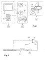
- the lock as schematically shown in Figure 1 has a instrument 10 for entering data into the lock, an electronic circuit of information processing 12 and a control system 14 of the locking and unlocking.
- the instrument 10 has a keyboard 16 and a screen 18, allowing respectively the user to enter and obtain relative information current operations.
- the electronic circuit includes a microprocessor 20, a memory 22 of type ROM, containing the control programs, a set of 24 programmable memories, E2PROM type, allowing to memorize successive values intended for managing the opening of the lock and a set of volatile memories 25, of RAM type, in which are defined registers which will be described in more detail with reference to Figures 2, 3 and 4.
- the control system 14 comprises a motor 26 and a lock 28, driven by a wheel 27 secured to the axis of the motor 26.
- the lock could also be controlled by an electromagnet.
- the lock as described allows, for example, to control the opening a cash machine.
- the person responsible for ensure loading must occur, it requests an access code to the company managing this distributor.
- the code is defined by a central unit, which will be the subject of a more detailed description with reference to FIG. 5a.
- the code is entered using the keyboard 16.
- the microprocessor 20 processes the values contained in the corresponding reprogrammable memories 24 to the last recognized code as well as the new code entered, to obtain a REF reference value, function only of reference values earlier, and a current CRT value. If there is a match between REF and CRT, it allows the opening of lock 28 and stores the new values obtained by combining the old values and the code entered.
- LFSR Linear feed shift register
- Figure 2 It includes, in this figure, a shift register 30, comprising forty cells numbered from 0 to 39 and each containing an element of a recorded binary value, and a gate Exclusive OR 32, one of the inputs of which, bearing the reference 32a, is connected to the row 1 cell and the other 32b to the row 32 cell.
- the output 32c is connected to the input of the shift register 30, that is to say the cell of rank 0 .
- a new element is introduced into the row 0 cell at each clock signal CLK and the content of the cells is shifted by one row.
- the value entered is defined by the contents of the shift register itself.
- the new value entered is defined by the values contained in the cells of rank 1 and 32 which are respectively connected to the inputs 32a and 32b of the gate 32.
- Figure 3 shows a combination combination recurrence shift register values, intended to define a new current value CRT, starting from the old current value and an INT input value whose characteristics will be specified later. It has two registers to offsets 36 and 38 and two exclusive OR doors 40 and 42, each having two inputs defined by the letters a and b and an output defined by the letter c.
- the access code in decimal code, entered into the lock using the keypad 16.
- An electronic circuit 43 transforms it into binary code, defining a input value INT, introduced into register 38 by parallel loading.
- the two shift registers 36 and 38 each include forty cells, numbered from 0 to 39 .
- the inputs 40a and 40b of the door 40 are respectively connected to the cells of rows 1 and 32 of the register 36.
- the inputs 42a and 42b of the door 42 are respectively connected to the output 40c of the door 40 and to the cell of the row 39 from register 38.
- the register 36 therefore initially contains the value CRT originating from the previous transaction and the register 38 the value INT newly introduced.
- the logic states of these two inputs define binary information introduced into the row 0 cell of register 36. In this way, each time a clock signal is applied to register 38, its content is shifted by one row and a bit is introduced into register 36, a function its own content and that of the register 38.
- a value combination recurrence shift register allows to obtain a predictable value, from two known values. It is however extremely difficult to determine this value if one does not know not the structure of the shift registers.
- the door 50 comprises two inputs 50a and 50b respectively connected to the cells of rows 32 and 1 of the register 44.
- the door 52 comprises inputs 52a and 52b respectively connected to the output 50c of the door 50 and to the cell row 39 of register 48.
- the switch 54 comprises two inputs 54a and 54b and two outputs 54c and 54d.
- the row 39 cell of the register 48 is also connected to the first input 54a of the switch 54.
- the second input 54b is connected to the output 52c of the door 52.
- the outputs 54c and 54d are respectively connected to the cells of rank 0 registers 44 and 46.
- register 46 The content of register 46 is then transformed into decimal code by means not shown in the drawing, the number obtained taking the place of code access.
- Figure 5a shows, schematically, the device of the central unit intended to define the successive access codes of a control lock dynamic, the logic device of which is shown in Figure 5b.
- the central unit device has two reprogrammable memories 58 and 60, a value processing recurrence shift register 62, such that defined with reference to FIG. 2 and a shift register with recurrence of combination and mixing 63, as defined with reference to FIG. 4.
- the constituent parts of these registers bear the same references as those used in these figures.
- It also includes two shift registers 64 and 68, and a logic processing unit 70 comprising means schematically represented in 72 and 76, and intended to ensure an AND logic function and an OR logic function respectively.
- Memories 58 and 60 respectively contain REF and CRT values whose characteristics will be specified later.
- the registers 64 and 68 have the same number of cells.
- the register 64 contains a constant MAS value, defining the cells whose content is encrypted, identified by 1, while cells with clear content contain a 0.
- Register 68 is intended to receive a random value ALE. It is obtained from a random binary number, comprising as many digits as the registers have cells, generated by the unit central by means known to those skilled in the art and not shown in drawing, and treated by comparison with the contents of register 64 so that for all the cells of register 64 containing a 1, the cell of the same rank of register 68 is brought to 0. In this way, the cells occupied by the variable elements of the ALE value correspond to the cells of register 64 whose content is equal to 0. The other cells contain the value 0.
- the contents of memories 58 and 60 are respectively introduced, by parallel loading, in the registers 30 of the shift register at recurrence of value processing 62, and 44 of the shift register at combination recurrence and mixing 63.
- a CLK REF clock signal is applied to register 30, to define a new REF value.
- registers 30, 64 and 68 are then processed in parallel, by means of the logic processing unit 70. More specifies, the contents of registers 30 and 64 are processed using the AND function represented in 72. The value thus obtained is equal to the content of register 30 when the content of register 64 is equal to 1, and to 0 in the other cases.
- a CLK clock signal is then applied to registers 44, 46, 48 and 64.
- the information contained in register 64 commands the switch 54 so that the signals from register 48 are directly entered into register 46 when the contents of the cell of register 64 is equal to 0 and in register 44 when it is equal to 1.
- register 46 contains the value, called INT, comprising a random part and a part intended for controlling opening the lock.
- INT is then transformed into code decimal, by means not shown, to make it read and easier processing. The code is thus transmitted to the person who is to open the lock.
- the access code is processed, after introduction using the keyboard and transformation into binary value, by the logical device of the lock as shown in Figure 5b.
- This device includes, for this purpose, two reprogrammable memories 80 and 82, a shift register with value processing recurrence 84, as defined with reference to the figure 2 and a combination of values 86 recurrence shift register, such as defined with reference to Figure 3.
- the constituent parts of these registers bear the same references as those used in these figures.
- This device further comprises a shift register 88, and a unit for logic processing 90 comprising means schematically represented in 92, 94 and 96, and intended to ensure respectively logical functions OR exclusive, AND and SI.
- Memories 80 and 82 respectively contain REF and CRT values, equal to the values contained in the central unit. To make it so, there suffices that at the start, equal values are entered in the memories the lock and the central unit. These values adjust then automatically.
- Register 88 contains a constant value MAS equal to the value contained in register 64.
- the starting of the system causes the respective transfer of the contents of memories 80 and 82 in the registers 30 and 36.
- the access code decimal
- the access code is transformed into binary and gives the value INT introduced in parallel in register 38.
- the content of this register is then processed by the combination value shift register 86.
- the content of register 30 is processed as explained in reference to figure 2.
- Elements of cells of the same rank in registers 30, 36 and 88 are then processed in parallel by means of the logic unit 90. Whenever elements of the same rank in registers 30 and 36 are equal, the element resulting from the exclusive OR function is equal to 0, while if they differ, it is equal to 1. By treating the resulting elements with the same elements rank of the MAS value contained in register 88, by means of the function AND 94, the variable elements of the ALE value are always equal to 0. In other words if all the same encrypted items of registers 30 and 36 are equal, the signal from the AND gate is always equal to 0. If this is if so, the IF function answers YES and the lock is open or released. If at contrary, at least one of the encrypted elements differs, the IF function responds NO and the lock remains blocked.
- the person requesting the code gives a receipt to the central unit which transfer to memories 58 and 60 the respective contents of registers 30 and 44, as new REF and current CRT reference values, in the device as described with reference to FIG. 5a.
- the decimal code given to the person to open the lock is defined by the combination of elements obtained from the processing of the stored values REF and CRT and random elements. So it is impossible, based on the code as well given, to determine precisely what will be the value of the next code to introduce. Also, even knowing the ranks of the cells containing elements relating to the random part, it is impossible to define a code to come without knowing, at the same time, the content of the REF values and CRT and the structure of recurrence shift registers.
- the dynamically controlled system can be associated with a classic constant code system.
Landscapes
- Physics & Mathematics (AREA)
- General Physics & Mathematics (AREA)
- Storage Device Security (AREA)
- Lock And Its Accessories (AREA)
- Selective Calling Equipment (AREA)
Claims (11)
- Elektronisches Schloss mit dynamischer Steuerung und mit einem Instrument (10) zur Eingabe von Daten, einer elektromagnetischen Betätigungsvorrichtung (26) zur Steuerung eines Riegels (28) und einem elektronischen Regelkreis (12) mit:dadurch gekennzeichnet, dass die besagte Verarbeitungseinheit so ausgelegt ist, um:einem ersten Speicher (80) zur Speicherung eines Referenzwertes (REF),einem zweiten Speicher (82) zur Speicherung eines laufenden Wertes (CRT),einer Verarbeitungseinheit mit einem ersten Verzeichnis (30) zum Ausführen einer Funktion zum Referenzwert (REF), einem zweiten Verzeichnis (36) zur Verarbeitung des laufenden Wertes (CRT), einem dritten Verzeichnis (38) zur Verarbeitung eines Eingangswertes (INT), Mitteln zur Übertragung des Referenzwertes (REF) und des laufenden Wertes (CRT) aus ihrem Speicher in ihr jeweiliges Verzeichnis und umgekehrt und logischen Mitteln (32, 40, 42, 90),den Referenzwert (REF) zu verarbeiten, der im ersten Verzeichnis eingetragen ist, um so einen neuen Referenzwert zu definieren, der im ersten Verzeichnis (30) den vorhergehenden Wert (REF) ersetzt,den laufenden Wert (CRT), der im zweiten Verzeichnis (36) enthalten ist und den Eingangswert (INT), der im dritten Verzeichnis (38) enthalten ist, zu kombinieren, um einen neuen laufenden Wert zu definieren, der im zweiten Verzeichnis (36) enthalten ist,den Inhalt des ersten (30) und zweiten (36) Verzeichnisses zu vergleichen und,lediglich in Fällen der Übereinstimmung einen Befehl an die elektromagnetische Betätigungsvorrichtung (26) zur Steuerung des Riegels (28) zu senden und um im ersten Speicher (80) den Referenzwert, der sich dort befindet, durch den neuen Referenzwert zu ersetzen, der sich im ersten Verzeichnis (30) befindet und um im zweiten Speicher (82) den laufenden Wert, der sich dort befindet, durch den neuen laufenden Wert zu ersetzen, der im zweiten Verzeichnis (36) enthalten ist.
- Schloss nach Anspruch 1, dadurch gekennzeichnet, dass die besagte Verarbeitungseinheit zeitversetzte Verzeichnisse enthält, die jeweils über Zellen verfügen, die von 0 bis n nummeriert sind und in denen die letzte eingegebene Information die Zelle mit dem niedrigsten Rang belegt.
- Elektronisches Schloss mit dynamischer Steuerung gemäß Anspruch 2, dadurch gekennzeichnet, dass die besagte Verarbeitungseinheit unter anderem drei ausschließliche ODER-Ports (32, 40, 42) enthält, die jeweils mit zwei Eingängen und einem Ausgang versehen sind und zusammen mit den besagten Verzeichnissen:ein Verzeichnis mit einer wiederholten Versatzzeit (84) zur Verarbeitung des Wertes, das ein erstes zeitversetztes Verzeichnis (30) und einen ausschließlichen ODER-Port (32) zur Verarbeitung des früheren Referenzwertes umfasst, mit dem Ziel des Erhalts eines neuen Referenzwertes undein kombiniertes Verzeichnis mit einer wiederholten Versatzzeit (86), das ein zweites Verzeichnis mit einer wiederholten Versatzzeit (36), in das der laufende Wert (CRT) eingegeben wird und ein drittes zeitversetztes Verzeichnis (38), in das der Eingangswert (INT) eingegeben wird und zwei ausschließliche ODER-Ports (40, 42) zur Kombination des aktuellen Wertes und des Eingangswertes und zur Definition eines neuen laufenden Wertes enthält, beschreibt.
- Schloss gemäß Anspruch 3, dadurch gekennzeichnet, dass die Verarbeitungseinheit unter anderem eine logische Verarbeitungseinheit (90) enthält, um zu prüfen, ob die Zellen desselben Rangs eines Teils von mindestens dem ersten und zweiten zeitversetzten Verzeichnis einen (30, 36) identischen Inhalt haben.
- Schloss nach einem der Ansprüche 1 bis 3, dadurch gekennzeichnet, dass die besagte Verarbeitungseinheit so ausgelegt ist, dass sie lediglich einen Teil der Elemente des laufenden Wertes (CRT) und des Referenzwertes (REF) vergleicht.
- Schloss nach einem der Ansprüche 4 und 5, dadurch gekennzeichnet, dass die logische Verarbeitungseinheit (90) lediglich einen Teil der Zellen des ersten und zweiten zeitversetzten Verzeichnisses (30, 36) vergleicht.
- Steuersystem mit einer zentralen Steuervorrichtung und mindestens einem Schloss gemäß Anspruch 1, dadurch gekennzeichnet, dass die besagte Vorrichtung:einen ersten Speicher (58) zur Speicherung eines Referenzwertes (REF), der gleich hoch ist wie der Referenzwert im ersten Speicher (80) des Schlosses,einen zweiten Speicher (60) zur Speicherung eines laufenden Wertes (CRT), der gleich hoch ist wie der Referenzwert im zweiten Speicher (82) des Schlosses,eine Verarbeitungseinheit mit:einem ersten Verzeichnis (30) zur Verarbeitung des Referenzwertes (REF),einem zweiten Verzeichnis (44) zur Verarbeitung des laufenden Wertes (CRT),Mitteln zur Übertragung des Referenzwertes (REF) und des laufenden Wertes (CRT) aus ihrem Speicher in ihr jeweiliges Verzeichnis und umgekehrt,Mitteln (62) zur Verarbeitung des Referenzwertes, der im ersten Verzeichnis (30) enthalten ist, zur Definition eines neuen Referenzwertes, der den Wert ersetzt, der zuvor im ersten Verzeichnis enthalten war,Mitteln (63) zur Kombination des laufenden Wertes, der im zweiten Verzeichnis (44) enthalten ist und des neuen Referenzwertes zur Definition eines Eingangswertes, der in einem dritten Verzeichnis enthalten ist und eines neuen laufenden Wertes, der im zweiten Verzeichnis enthalten ist, umfasst.
- Steuersystem gemäß Anspruch 7, dadurch gekennzeichnet, dass die Verarbeitungseinheit und das Schloss zeitversetzte Verzeichnisse (30, 36, 38, 44, 46, 48, 64, 66, 68, 88) enthalten, die jeweils Zellen umfassen, die von 0 bis n nummeriert sind und in denen die letzte eingegebene Information die Zelle mit dem niedrigsten Rang belegt.
- Steuersystem nach Anspruch 8, dadurch gekennzeichnet, dass die Verarbeitungseinheit des Schlosses unter anderem drei ausschließliche ODER-Ports (32, 40, 42) umfasst, die jeweils mit zwei Eingängen und einem Ausgang versehen sind und mit den besagten Verzeichnissen:und dadurch gekennzeichnet, dass die Verarbeitungseinheit der besagten Vorrichtung unter anderem drei ausschließliche ODER-Ports (32, 50, 52) und einen Umschalter (54) umfasst, die gemeinsam:ein Verzeichnis mit wiederholter Versatzzeit (84) zur Verarbeitung des Wertes, das ein erstes zeitversetztes Verzeichnis (30) umfasst, in das der Referenzwert (REF) eingegeben wird sowie einen ausschließlichen ODER-Port (32) zur Verarbeitung des vorherigen Referenzwertes mit dem Ziel des Erhalts eines neuen Referenzwertes undein Verzeichnis mit wiederholter Versatzzeit (86) zur Kombination beschreibt, das ein zweites zeitversetztes Verzeichnis (36) umfasst, in das der laufende Wert (CRT) eingegeben wird sowie ein drittes zeitversetztes Verzeichnis (38), in das der Eingangswert (INT) und zwei ausschließliche ODER-Ports (40, 42) eingegeben werden, um den laufenden Wert und den Eingangswert zu kombinieren und um einen neuen laufenden Wert zu definieren,ein Verzeichnis mit wiederholter Versatzzeit (62) zur Verarbeitung eines Wertes, das ein erstes zeitversetztes Verzeichnis (30), in das der Referenzwert (REF) eingegeben wird und einen ausschließlichen ODER-Port (32) zur Verarbeitung des vorherigen Referenzwertes im Hinblick auf den Erhalt eines neuen Referenzwertes umfasst undein Verzeichnis mit wiederholter Versatzzeit zur Kombination und Zusammenführung (63) beschreiben, das ein zweites zeitversetztes Verzeichnis (44) umfasst, in das der laufende Wert (CRT) eingegeben wird sowie ein drittes zeitversetztes Verzeichnis (46), in das der Eingangswert (INT) eingegeben wird und ein viertes zeitversetztes Verzeichnis (48), in das ein Wert eingegeben wird, der zumindest mittelbar aus dem ersten zeitversetzten Verzeichnis (30) stammt und zwei ausschließliche ODER-Ports (40, 42) zur Verarbeitung des Wertes, der im vierten Verzeichnis enthalten ist und des vorherigen laufenden Wertes im Hinblick auf den Erhalt eines Eingangswertes (INT) und eines neuen laufenden Wertes (CRT).
- System gemäß Anspruch 9, dadurch gekennzeichnet, dass die Verarbeitungseinheit des Schlosses unter anderem eine logische Verarbeitungseinheit (90) enthält, um zu prüfen, ob die Zellen desselben Rangs eines Teils zumindest des ersten (30) und zweiten Verzeichnisses (36) einen identischen Inhalt haben.
- System nach Anspruch 10, dadurch gekennzeichnet, dass die besagte logische Verarbeitungseinheit (90) des Schlosses so ausgelegt ist, dass sie lediglich einen Teil der Elemente des laufenden Wertes (CRT) und des Referenzwertes (REF) vergleicht und dadurch gekennzeichnet, dass die Verarbeitungseinheit der besagten Vorrichtung unter anderem eine logische Verarbeitungseinheit (70) zur Verarbeitung des Referenzwertes (REF) umfasst, der im ersten zeitversetzten Verzeichnis (30) enthalten ist und zur Eingabe eines Wertes nach der Verarbeitung in das besagte vierte zeitversetzte Verzeichnis (48), ein fünftes (64) und ein sechstes zeitversetztes Verzeichnis (68), die mit der logischen Verarbeitungseinheit (70) zusammenarbeiten, um jeweils eine gewisse Anzahl von Zellen des ersten Verzeichnisses (30) zu maskieren und zur Eingabe eines zufälligen Wertes (ALE) in die Zellen, deren Elemente nicht Gegenstand des besagten Vergleichs sind.
Applications Claiming Priority (2)
| Application Number | Priority Date | Filing Date | Title |
|---|---|---|---|
| FR9811397 | 1998-09-10 | ||
| FR9811397A FR2783270B1 (fr) | 1998-09-10 | 1998-09-10 | Serrure electronique a commande dynamique et systeme de commande muni d'une telle serrure |
Publications (2)
| Publication Number | Publication Date |
|---|---|
| EP0985790A1 EP0985790A1 (de) | 2000-03-15 |
| EP0985790B1 true EP0985790B1 (de) | 2004-03-03 |
Family
ID=9530369
Family Applications (1)
| Application Number | Title | Priority Date | Filing Date |
|---|---|---|---|
| EP99117014A Expired - Lifetime EP0985790B1 (de) | 1998-09-10 | 1999-08-30 | Dynamisch gesteuertes elektronisches Schloss und mit einem solchen Schloss versehenes Steuerungssystem |
Country Status (5)
| Country | Link |
|---|---|
| US (1) | US6445281B1 (de) |
| EP (1) | EP0985790B1 (de) |
| AT (1) | ATE261042T1 (de) |
| DE (1) | DE69915195D1 (de) |
| FR (1) | FR2783270B1 (de) |
Families Citing this family (5)
| Publication number | Priority date | Publication date | Assignee | Title |
|---|---|---|---|---|
| EP1244069A1 (de) | 2001-03-20 | 2002-09-25 | MR Electronic SA | Vorrichtung zur Begrenzung des Zugriffs zu einem geschlossenen Raum |
| US7420456B2 (en) * | 2004-03-19 | 2008-09-02 | Sentri Lock, Inc. | Electronic lock box with multiple modes and security states |
| DE102006003128A1 (de) * | 2006-01-23 | 2007-07-26 | Siemens Ag | Bedrohungserkennungssystem und Verriegelungseinrichtung |
| EP2050902A1 (de) * | 2007-10-18 | 2009-04-22 | USM Holding AG | Mechatronisches Möbelschloss |
| EP2813647B1 (de) * | 2013-06-11 | 2019-03-13 | iLOQ Oy | Elektromechanisches Schloss |
Family Cites Families (6)
| Publication number | Priority date | Publication date | Assignee | Title |
|---|---|---|---|---|
| US4038637A (en) * | 1975-11-24 | 1977-07-26 | Peters Sherman M | Access control system |
| JPS6017913B2 (ja) * | 1981-04-30 | 1985-05-07 | 日産自動車株式会社 | 電子錠 |
| US5363448A (en) * | 1993-06-30 | 1994-11-08 | United Technologies Automotive, Inc. | Pseudorandom number generation and cryptographic authentication |
| CA2133057C (en) | 1993-10-20 | 2005-03-15 | Gerald Lee Dawson | Electronic combination lock utilizing a one-time use combination |
| US5420925A (en) * | 1994-03-03 | 1995-05-30 | Lectron Products, Inc. | Rolling code encryption process for remote keyless entry system |
| GB2306722B (en) * | 1995-10-24 | 2000-02-09 | Motorola Inc | Encryption/decryption circuit, method and system |
-
1998
- 1998-09-10 FR FR9811397A patent/FR2783270B1/fr not_active Expired - Fee Related
-
1999
- 1999-08-30 EP EP99117014A patent/EP0985790B1/de not_active Expired - Lifetime
- 1999-08-30 DE DE69915195T patent/DE69915195D1/de not_active Expired - Lifetime
- 1999-08-30 AT AT99117014T patent/ATE261042T1/de not_active IP Right Cessation
- 1999-09-09 US US09/392,491 patent/US6445281B1/en not_active Expired - Lifetime
Also Published As
| Publication number | Publication date |
|---|---|
| EP0985790A1 (de) | 2000-03-15 |
| FR2783270A1 (fr) | 2000-03-17 |
| FR2783270B1 (fr) | 2000-11-17 |
| US6445281B1 (en) | 2002-09-03 |
| ATE261042T1 (de) | 2004-03-15 |
| DE69915195D1 (de) | 2004-04-08 |
Similar Documents
| Publication | Publication Date | Title |
|---|---|---|
| EP0670063B1 (de) | Verfahren und schaltung zur verschluesselung und authentisierung von speicherkarten | |
| EP0089876B1 (de) | Verfahren und Vorrichtung zur Sicherung von einem Lieferanten an einen Benutzer ausgelieferten Software | |
| FR2497617A1 (fr) | Procede et dispositif de securite pour communication tripartie de donnees confidentielles | |
| EP1055203B1 (de) | Zugangskontrollprotokoll zwischen einem schlüssel und einem elektronischen schloss | |
| FR2471632A1 (fr) | Appareil et procede pour coder et decoder une carte delivree a un individu par une entite | |
| EP1064752B1 (de) | Verfahren zur datensicherung welches einen krypto-algorithmus verwendet | |
| EP0044039A1 (de) | Individualisierter, tragbarer Gegenstand der Kreditkartenart | |
| OA10739A (fr) | Dispositif électronique de fermeture programmable | |
| FR2542471A1 (fr) | Procede et appareil pour assurer la securite de l'acces a des fichiers | |
| EP0434551A1 (de) | Verfahren zur Erzeugung einer Pseudozufallszahl in einem Datenbearbeitungssystem und ein System zur Ausführung dieses Verfahrens | |
| FR2681165A1 (fr) | Procede de transmission d'information confidentielle entre deux cartes a puces. | |
| EP0891611B1 (de) | Zugangskontrollsystem zu einer funktion, in der die chiffrierung mehreredynamische veränderliche enthält. | |
| EP0985790B1 (de) | Dynamisch gesteuertes elektronisches Schloss und mit einem solchen Schloss versehenes Steuerungssystem | |
| EP0553163A1 (de) | Verfahren zur aufteilung des speichers eines integrierten schaltung für mehrere anwendungen | |
| EP0126699A1 (de) | Elektronische Identifizierungsvorrichtung | |
| EP0419306B1 (de) | Verfahren und Vorrichtung zum Erzeugen und Bestätigen einer numerischen Botschaft und Anwendung einer solchen Vorrichtung | |
| EP0856624A1 (de) | Sicherheitsvorrichtung für Kraftfahrzeuge und Lernverfahren dafür | |
| FR2600188A1 (fr) | Procede d'habilitation d'un milieu exterieur par un objet portatif relie a ce milieu | |
| EP2691941B1 (de) | Verfahren und vorrichtung zur betätigung eines schlosses | |
| EP1399896A1 (de) | Kryptographisches verfahren zum schutz eines elektronischen chips gegen betrug | |
| FR2788353A1 (fr) | Microprocesseur avec circuits de protection pour securiser l'acces a ses registres | |
| FR2834366A1 (fr) | Carte a puce autoverrouillable, dispositif de securisation d'une telle carte et procedes associes | |
| FR2657446A1 (fr) | Procede et dispositif destine a controler et a permettre l'acces a un site ou a un service. | |
| FR2710769A1 (fr) | Système de traitement des données d'une carte à microcircuit, carte et lecteur pour ce système et procédé de mise en Óoeuvre. | |
| WO2005050419A1 (fr) | Procede de securisation d'une image d'une donnee biometrique d'authentification et procede d'authentification d'un utilisateur a partir d'une image d'une donnee biometrique d'authentification |
Legal Events
| Date | Code | Title | Description |
|---|---|---|---|
| PUAI | Public reference made under article 153(3) epc to a published international application that has entered the european phase |
Free format text: ORIGINAL CODE: 0009012 |
|
| AK | Designated contracting states |
Kind code of ref document: A1 Designated state(s): AT BE CH CY DE DK ES FI FR GB GR IE IT LI LU MC NL PT SE |
|
| AX | Request for extension of the european patent |
Free format text: AL;LT;LV;MK;RO;SI |
|
| 17P | Request for examination filed |
Effective date: 20000830 |
|
| AKX | Designation fees paid |
Free format text: AT BE CH CY DE DK ES FI FR GB GR IE IT LI LU MC NL PT SE |
|
| 17Q | First examination report despatched |
Effective date: 20030226 |
|
| GRAP | Despatch of communication of intention to grant a patent |
Free format text: ORIGINAL CODE: EPIDOSNIGR1 |
|
| GRAS | Grant fee paid |
Free format text: ORIGINAL CODE: EPIDOSNIGR3 |
|
| GRAA | (expected) grant |
Free format text: ORIGINAL CODE: 0009210 |
|
| AK | Designated contracting states |
Kind code of ref document: B1 Designated state(s): AT BE CH CY DE DK ES FI FR GB GR IE IT LI LU MC NL PT SE |
|
| PG25 | Lapsed in a contracting state [announced via postgrant information from national office to epo] |
Ref country code: IE Free format text: LAPSE BECAUSE OF FAILURE TO SUBMIT A TRANSLATION OF THE DESCRIPTION OR TO PAY THE FEE WITHIN THE PRESCRIBED TIME-LIMIT Effective date: 20040303 Ref country code: FI Free format text: LAPSE BECAUSE OF FAILURE TO SUBMIT A TRANSLATION OF THE DESCRIPTION OR TO PAY THE FEE WITHIN THE PRESCRIBED TIME-LIMIT Effective date: 20040303 Ref country code: CY Free format text: LAPSE BECAUSE OF FAILURE TO SUBMIT A TRANSLATION OF THE DESCRIPTION OR TO PAY THE FEE WITHIN THE PRESCRIBED TIME-LIMIT Effective date: 20040303 Ref country code: AT Free format text: LAPSE BECAUSE OF FAILURE TO SUBMIT A TRANSLATION OF THE DESCRIPTION OR TO PAY THE FEE WITHIN THE PRESCRIBED TIME-LIMIT Effective date: 20040303 |
|
| REG | Reference to a national code |
Ref country code: GB Ref legal event code: FG4D Free format text: NOT ENGLISH |
|
| REG | Reference to a national code |
Ref country code: CH Ref legal event code: EP |
|
| REG | Reference to a national code |
Ref country code: IE Ref legal event code: FG4D Free format text: FRENCH |
|
| REF | Corresponds to: |
Ref document number: 69915195 Country of ref document: DE Date of ref document: 20040408 Kind code of ref document: P |
|
| PG25 | Lapsed in a contracting state [announced via postgrant information from national office to epo] |
Ref country code: SE Free format text: LAPSE BECAUSE OF FAILURE TO SUBMIT A TRANSLATION OF THE DESCRIPTION OR TO PAY THE FEE WITHIN THE PRESCRIBED TIME-LIMIT Effective date: 20040603 Ref country code: GR Free format text: LAPSE BECAUSE OF FAILURE TO SUBMIT A TRANSLATION OF THE DESCRIPTION OR TO PAY THE FEE WITHIN THE PRESCRIBED TIME-LIMIT Effective date: 20040603 Ref country code: DK Free format text: LAPSE BECAUSE OF FAILURE TO SUBMIT A TRANSLATION OF THE DESCRIPTION OR TO PAY THE FEE WITHIN THE PRESCRIBED TIME-LIMIT Effective date: 20040603 |
|
| PG25 | Lapsed in a contracting state [announced via postgrant information from national office to epo] |
Ref country code: DE Free format text: LAPSE BECAUSE OF FAILURE TO SUBMIT A TRANSLATION OF THE DESCRIPTION OR TO PAY THE FEE WITHIN THE PRESCRIBED TIME-LIMIT Effective date: 20040604 |
|
| PG25 | Lapsed in a contracting state [announced via postgrant information from national office to epo] |
Ref country code: ES Free format text: LAPSE BECAUSE OF FAILURE TO SUBMIT A TRANSLATION OF THE DESCRIPTION OR TO PAY THE FEE WITHIN THE PRESCRIBED TIME-LIMIT Effective date: 20040614 |
|
| REG | Reference to a national code |
Ref country code: CH Ref legal event code: NV Representative=s name: GLN GRESSET & LAESSER NEUCHATEL CABINET DE CONSEIL |
|
| GBT | Gb: translation of ep patent filed (gb section 77(6)(a)/1977) |
Effective date: 20040628 |
|
| PG25 | Lapsed in a contracting state [announced via postgrant information from national office to epo] |
Ref country code: LU Free format text: LAPSE BECAUSE OF NON-PAYMENT OF DUE FEES Effective date: 20040830 |
|
| PG25 | Lapsed in a contracting state [announced via postgrant information from national office to epo] |
Ref country code: MC Free format text: LAPSE BECAUSE OF NON-PAYMENT OF DUE FEES Effective date: 20040831 Ref country code: BE Free format text: LAPSE BECAUSE OF NON-PAYMENT OF DUE FEES Effective date: 20040831 |
|
| REG | Reference to a national code |
Ref country code: IE Ref legal event code: FD4D |
|
| PLBE | No opposition filed within time limit |
Free format text: ORIGINAL CODE: 0009261 |
|
| STAA | Information on the status of an ep patent application or granted ep patent |
Free format text: STATUS: NO OPPOSITION FILED WITHIN TIME LIMIT |
|
| 26N | No opposition filed |
Effective date: 20041206 |
|
| BERE | Be: lapsed |
Owner name: S.A. *MR ELECTRONIC Effective date: 20040831 |
|
| BERE | Be: lapsed |
Owner name: S.A. *MR ELECTRONIC Effective date: 20040831 |
|
| PG25 | Lapsed in a contracting state [announced via postgrant information from national office to epo] |
Ref country code: PT Free format text: LAPSE BECAUSE OF NON-PAYMENT OF DUE FEES Effective date: 20040803 |
|
| REG | Reference to a national code |
Ref country code: CH Ref legal event code: PFA Owner name: MR ELECTRONIC SA, CH Free format text: FORMER OWNER: MR ELECTRONIC SA, CH |
|
| REG | Reference to a national code |
Ref country code: FR Ref legal event code: PLFP Year of fee payment: 18 |
|
| PGFP | Annual fee paid to national office [announced via postgrant information from national office to epo] |
Ref country code: NL Payment date: 20160826 Year of fee payment: 18 |
|
| PGFP | Annual fee paid to national office [announced via postgrant information from national office to epo] |
Ref country code: CH Payment date: 20160829 Year of fee payment: 18 Ref country code: GB Payment date: 20160830 Year of fee payment: 18 |
|
| PGFP | Annual fee paid to national office [announced via postgrant information from national office to epo] |
Ref country code: FR Payment date: 20160825 Year of fee payment: 18 |
|
| REG | Reference to a national code |
Ref country code: CH Ref legal event code: PFA Owner name: MR ELECTRONIC SA, CH Free format text: FORMER OWNER: MR ELECTRONIC SA, CH |
|
| REG | Reference to a national code |
Ref country code: CH Ref legal event code: PFA Owner name: DORMAKABA SCHWEIZ AG, CH Free format text: FORMER OWNER: MR ELECTRONIC SA, CH |
|
| REG | Reference to a national code |
Ref country code: NL Ref legal event code: PD Owner name: KABA AG; CH Free format text: DETAILS ASSIGNMENT: CHANGE OF OWNER(S), MERGE; FORMER OWNER NAME: MR ELECTRONIC SA Effective date: 20170228 Ref country code: NL Ref legal event code: HC Owner name: DORMAKABA SCHWEIZ AG; CH Free format text: DETAILS ASSIGNMENT: CHANGE OF OWNER(S), CHANGE OF OWNER(S) NAME; FORMER OWNER NAME: KABA AG Effective date: 20170228 |
|
| REG | Reference to a national code |
Ref country code: GB Ref legal event code: 732E Free format text: REGISTERED BETWEEN 20170817 AND 20170823 |
|
| PGFP | Annual fee paid to national office [announced via postgrant information from national office to epo] |
Ref country code: IT Payment date: 20170823 Year of fee payment: 19 |
|
| REG | Reference to a national code |
Ref country code: CH Ref legal event code: PL |
|
| REG | Reference to a national code |
Ref country code: NL Ref legal event code: MM Effective date: 20170901 |
|
| GBPC | Gb: european patent ceased through non-payment of renewal fee |
Effective date: 20170830 |
|
| PG25 | Lapsed in a contracting state [announced via postgrant information from national office to epo] |
Ref country code: CH Free format text: LAPSE BECAUSE OF NON-PAYMENT OF DUE FEES Effective date: 20170831 Ref country code: LI Free format text: LAPSE BECAUSE OF NON-PAYMENT OF DUE FEES Effective date: 20170831 |
|
| REG | Reference to a national code |
Ref country code: FR Ref legal event code: ST Effective date: 20180430 |
|
| PG25 | Lapsed in a contracting state [announced via postgrant information from national office to epo] |
Ref country code: NL Free format text: LAPSE BECAUSE OF NON-PAYMENT OF DUE FEES Effective date: 20170901 |
|
| PG25 | Lapsed in a contracting state [announced via postgrant information from national office to epo] |
Ref country code: GB Free format text: LAPSE BECAUSE OF NON-PAYMENT OF DUE FEES Effective date: 20170830 |
|
| PG25 | Lapsed in a contracting state [announced via postgrant information from national office to epo] |
Ref country code: FR Free format text: LAPSE BECAUSE OF NON-PAYMENT OF DUE FEES Effective date: 20170831 |
|
| PG25 | Lapsed in a contracting state [announced via postgrant information from national office to epo] |
Ref country code: IT Free format text: LAPSE BECAUSE OF NON-PAYMENT OF DUE FEES Effective date: 20180830 |