EP0985853B1 - Fahrzeuggetriebe - Google Patents
Fahrzeuggetriebe Download PDFInfo
- Publication number
- EP0985853B1 EP0985853B1 EP99117276A EP99117276A EP0985853B1 EP 0985853 B1 EP0985853 B1 EP 0985853B1 EP 99117276 A EP99117276 A EP 99117276A EP 99117276 A EP99117276 A EP 99117276A EP 0985853 B1 EP0985853 B1 EP 0985853B1
- Authority
- EP
- European Patent Office
- Prior art keywords
- pulley
- oil
- chamber
- pulleys
- cover
- Prior art date
- Legal status (The legal status is an assumption and is not a legal conclusion. Google has not performed a legal analysis and makes no representation as to the accuracy of the status listed.)
- Expired - Lifetime
Links
- 230000005540 biological transmission Effects 0.000 title claims description 63
- 239000003921 oil Substances 0.000 claims description 165
- 230000033001 locomotion Effects 0.000 claims description 6
- 239000010687 lubricating oil Substances 0.000 claims description 5
- 230000002093 peripheral effect Effects 0.000 claims description 4
- 238000001514 detection method Methods 0.000 claims description 3
- 238000005461 lubrication Methods 0.000 description 62
- 230000007246 mechanism Effects 0.000 description 30
- 230000008859 change Effects 0.000 description 12
- 238000013019 agitation Methods 0.000 description 6
- 238000010276 construction Methods 0.000 description 6
- 239000010720 hydraulic oil Substances 0.000 description 5
- 230000009467 reduction Effects 0.000 description 5
- 238000001816 cooling Methods 0.000 description 2
- 230000003647 oxidation Effects 0.000 description 2
- 238000007254 oxidation reaction Methods 0.000 description 2
- 238000004904 shortening Methods 0.000 description 2
- 229910000831 Steel Inorganic materials 0.000 description 1
- 230000004308 accommodation Effects 0.000 description 1
- 230000009471 action Effects 0.000 description 1
- 229910052782 aluminium Inorganic materials 0.000 description 1
- XAGFODPZIPBFFR-UHFFFAOYSA-N aluminium Chemical compound [Al] XAGFODPZIPBFFR-UHFFFAOYSA-N 0.000 description 1
- 230000005587 bubbling Effects 0.000 description 1
- 230000015556 catabolic process Effects 0.000 description 1
- 230000003247 decreasing effect Effects 0.000 description 1
- 238000006731 degradation reaction Methods 0.000 description 1
- 238000010586 diagram Methods 0.000 description 1
- 230000000694 effects Effects 0.000 description 1
- 239000012530 fluid Substances 0.000 description 1
- 230000014509 gene expression Effects 0.000 description 1
- 230000001050 lubricating effect Effects 0.000 description 1
- 238000005259 measurement Methods 0.000 description 1
- 229910052751 metal Inorganic materials 0.000 description 1
- 239000002184 metal Substances 0.000 description 1
- 238000000034 method Methods 0.000 description 1
- 238000012986 modification Methods 0.000 description 1
- 230000004048 modification Effects 0.000 description 1
- 239000003129 oil well Substances 0.000 description 1
- 238000000746 purification Methods 0.000 description 1
- 239000010959 steel Substances 0.000 description 1
- 238000003756 stirring Methods 0.000 description 1
Images

Classifications
-
- F—MECHANICAL ENGINEERING; LIGHTING; HEATING; WEAPONS; BLASTING
- F16—ENGINEERING ELEMENTS AND UNITS; GENERAL MEASURES FOR PRODUCING AND MAINTAINING EFFECTIVE FUNCTIONING OF MACHINES OR INSTALLATIONS; THERMAL INSULATION IN GENERAL
- F16H—GEARING
- F16H57/00—General details of gearing
- F16H57/04—Features relating to lubrication or cooling or heating
- F16H57/048—Type of gearings to be lubricated, cooled or heated
- F16H57/0487—Friction gearings
- F16H57/0489—Friction gearings with endless flexible members, e.g. belt CVTs
-
- F—MECHANICAL ENGINEERING; LIGHTING; HEATING; WEAPONS; BLASTING
- F16—ENGINEERING ELEMENTS AND UNITS; GENERAL MEASURES FOR PRODUCING AND MAINTAINING EFFECTIVE FUNCTIONING OF MACHINES OR INSTALLATIONS; THERMAL INSULATION IN GENERAL
- F16H—GEARING
- F16H37/00—Combinations of mechanical gearings, not provided for in groups F16H1/00 - F16H35/00
- F16H37/02—Combinations of mechanical gearings, not provided for in groups F16H1/00 - F16H35/00 comprising essentially only toothed or friction gearings
- F16H37/021—Combinations of mechanical gearings, not provided for in groups F16H1/00 - F16H35/00 comprising essentially only toothed or friction gearings toothed gearing combined with continuously variable friction gearing
-
- F—MECHANICAL ENGINEERING; LIGHTING; HEATING; WEAPONS; BLASTING
- F16—ENGINEERING ELEMENTS AND UNITS; GENERAL MEASURES FOR PRODUCING AND MAINTAINING EFFECTIVE FUNCTIONING OF MACHINES OR INSTALLATIONS; THERMAL INSULATION IN GENERAL
- F16H—GEARING
- F16H57/00—General details of gearing
- F16H57/04—Features relating to lubrication or cooling or heating
- F16H57/042—Guidance of lubricant
- F16H57/0421—Guidance of lubricant on or within the casing, e.g. shields or baffles for collecting lubricant, tubes, pipes, grooves, channels or the like
- F16H57/0423—Lubricant guiding means mounted or supported on the casing, e.g. shields or baffles for collecting lubricant, tubes or pipes
-
- Y—GENERAL TAGGING OF NEW TECHNOLOGICAL DEVELOPMENTS; GENERAL TAGGING OF CROSS-SECTIONAL TECHNOLOGIES SPANNING OVER SEVERAL SECTIONS OF THE IPC; TECHNICAL SUBJECTS COVERED BY FORMER USPC CROSS-REFERENCE ART COLLECTIONS [XRACs] AND DIGESTS
- Y10—TECHNICAL SUBJECTS COVERED BY FORMER USPC
- Y10T—TECHNICAL SUBJECTS COVERED BY FORMER US CLASSIFICATION
- Y10T74/00—Machine element or mechanism
- Y10T74/21—Elements
- Y10T74/2186—Gear casings
- Y10T74/2189—Cooling
Definitions
- the present invention relates generally to a vehicular transmission according to the preamble part of claim 1.
- a transmission of the generic kind is known from document GB 2282646 A.
- This document shows a continuously variable transmission with a set of driving conical pulleys and a set of driven conical pulleys and a belt trained therearound.
- the driven set of conical pulleys is located lower than the set of driving pulleys, wherein the lowest portion of the driven pulleys is immersed in a secondary oil sump.
- a main oil sump containing the major part of the lubricating oil is separated from this lower set of pulleys by a separating rip formed in the housing of the transmission.
- Each set of pulleys contains a fixed pulley and an axially displaceable pulley in order to enable an adjustment of the gear change ratio.
- the circumference of the fixed pulley of the lower set of pulleys has teeth formed thereon for the purpose of measuring the rotational speed of the transmission output shaft to which the lower set of pulleys is connected. Furthermore, these teeth are used as conveying elements to convey oil from the secondary oil sump to the main oil sump.
- a housing rip is provided that extends from the lowest point of the secondary sump to above the vertex of the lower set of pulleys.
- This housing rip is formed in a L- or in an U-shape and serves as a transport channel through which the teeth provided on the circumference of the fixed pulley convey oil from the secondary oil sump to said main oil sump.
- a belt-type continuously variable transmission comprises a pair of pulleys, each pulley having a variable groove width, and a belt disposed therearound.
- the V-belt pitch radii of the pulleys are variable changed by adjusting the groove widths of the pulleys, so that the speed ratio of the transmission is continuously varied. It has been known that this type of transmission can be used on a vehicle as disclosed in Japanese Laid-Open Patent Publication No. H4(1992) - 258528 (A), which was filed by the same applicant as for this application.
- This vehicular continuously variable transmission comprises drive and driven pulleys, a belt, a forward-reverse selector mechanism, a starting mechanism, a reduction train, a differential mechanism, etc. in a hosing, and for lubricating these mechanisms, forced-feed lubrication or sprinkled lubrication by gear rotation is carried out.
- the oil used for this lubrication is also used as a hydraulic pressure controlling fluid (hydraulic oil) for controlling the adjustment of the groove widths of the drive and driven pulleys and for controlling a clutch.
- the hydraulic pressure which is used for the forced-feed lubrication and for the hydraulic control is generated by a hydraulic pump which is driven by an engine through a gear or a chain mounted on a shaft that is coupled to the engine, and the hydraulic pressure is delivered to the components which require lubrication and to the components which require hydraulic pressure control. After the hydraulic pressure is used for the respective purposes, the hydraulic oil flows downward from the respective components. Therefore, the transmission includes an oil well or an oil pan to collect the hydraulic oil, which is then recirculated by the hydraulic pump.
- the oil which has been used for the lubrication and for the actuation returns to the oil pan which is provided in the lower portion of the housing.
- the pulley chamber this room is hereinafter referred to as "the pulley chamber"
- some oil is thrown from the pulleys radially outward because of the rotation of the pulleys (centrifugal force).
- the oil flowing down along the inner walls of the pulley chamber is led into an inlet of an oil passage which is connected to the oil pan.
- an oil passage which is connected to the oil pan.
- each of the drive and driven pulleys typically includes about 20 to 30 raised portions, and proximity sensors which sense these protrusions are provided in the housing.
- the lubrication oil may be agitated by these raised portions, resulting a problem of bubbling of the lubrication oil.
- the agitation of the oil at a high temperature if it happens, promotes the oxidation and degradation of the lubrication oil.
- Japanese Laid ⁇ Open Patent Publication No. H8(1996)- 285023(A) discloses a method that provides a relatively large opening which leads directly to the oil pan, at the lower portion of the pulley chamber or an inlet for a discharge oil passage to return the oil which flows down along the inner walls to the oil pan, near the middle point of a line drawn between the two pulleys tangentially to the peripheries of the pulleys.
- the provision of a relatively large opening leading to the oil pan at the lower portion of the pulley chamber requires a compromise of the strength of the whole transmission housing including the pulley chamber, so there is a limit to the size of the opening.
- the level of the oil in the oil pan varies in correspondence to the driving condition of the vehicle, one of the pulleys positioned lower than the other may happen to be immersed into the oil. In this case, the above mentioned friction increases further.
- a vehicular transmission according to the present invention comprises a transmission device, which includes a drive pulley, a driven pulley and a belt which is disposed around these two pulleys for torque transmission, and a pulley chamber (also referred to as “chamber accommodating the transmission device” in claims or as “first room R1" in the following embodiment) which accommodates the transmission device.
- a pulley chamber also referred to as “chamber accommodating the transmission device” in claims or as “first room R1" in the following embodiment
- a raised portion is provided for the detection of the rotational speeds of the pulleys
- a cover is provided along the periphery of the drive or driven pulley that is positioned at the lower side of the chamber to cover the lower peripheral portion of the lower pulley, which includes the raised portion.
- the lubrication oil which flows down along the inner walls of the pulley chamber and accumulates at the bottom of the pulley chamber is isolated by the cover, which covers the lower periphery of the pulley which rotates at the lower position in the pulley chamber. Therefore, the amount of lubrication oil staying in the space partitioned by the cover for the lower pulley is relatively small, so this arrangement restricts agitation of the lubrication oil which may be caused by the rotation of the lower pulley. As a result, there isn't much rotational loss, and also, the lubrication oil can be usable for a relatively long period of time.
- the cover covers the lower peripheral portion of the pulley, which includes the raised portion used for the detection of the rotational speed of the pulley, the raised portion, which rotates and may cause the above mentioned problem of agitation, is isolated in the cover. Furthermore, as the rotational direction of the pulleys stays in one direction except when the vehicle moves backward, the direction of the flow of the lubrication oil in the cover also stays in the same direction. This condition keeps the rotational loss relatively small for the pulleys and makes the lubrication oil usable for a comparatively long period of time.
- a discharge opening is provided in said cover at the lowest portion of said cover in the mounted condition of said cover, said discharge opening being adapted to discharge lubricating oil from inside the cover to an oil pan situated lower than said chamber.
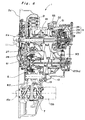
- FIGS. 6 and 7 show the construction of a belt-type continuously variable transmission 1.
- This belt-type continuously variable transmission 1 comprises a forward- reverse selector mechanism 3, a belt- type continuous speed change mechanism 4, a starting mechanism 5 (i.e., a starting clutch), a reduction train 6 (a train of gears 31 through 34), a differential mechanism 7, a power supply mechanism (including sprockets 91 and 92 and a chain 93) for transmitting power to an oil pump provided in a transmission housing 2, which is attached to an engine at an abutment surface 2a.
- the crank shaft Ks of the engine is coupled to a drive plate of a flying wheel which drives the input shaft 11 (also referred to as "first shaft") of the transmission according to the present invention.
- the driving force from the engine is transmitted from the first shaft S1 (including the input shaft 11 of the transmission) through a second shaft S2 (including the output shaft 12 of the transmission) and through each of the above mentioned mechanisms to a fourth shaft S4, which drives the axles 15a and 15b of a vehicle.
- the housing of the transmission comprises a first room R1, which accommodates the belt ⁇ type continuous speed change mechanism 4, a second room R2, which accommodates the starting mechanism 5, the reduction train 6, the differential mechanism 7, etc., and a third room R3, which accommodates the forward- reverse selector mechanism 3.
- a drive pulley 8 is provided for the belt-type continuous speed change mechanism 4 on the first shaft S1 in the first room R1, and the forward-reverse selector mechanism 3 is arranged in the third room R3.
- the crank shaft Ks of the engine is coupled to the input shaft 11 in the first shaft S1, and the input shaft 11 is connected to the forward-reverse selector mechanism 3 through the drive pulley 8, whose central part is hollow.
- the forward-reverse selector mechanism 3 comprises a double pinion type planetary gear 23 and includes a forward drive clutch 24, which directly connects the input shaft 11 to the drive pulley 8, and a rearward drive brake 25, which is capable of holding the ring gear stationary.
- a forward drive clutch 24 and rearward drive brake 25 are selectively activated, the drive pulley 8 is rotated clockwise or counter- clockwise with respect to the input shaft 11.
- the drive pulley 8 comprises a stationary pulley half 8a and a movable pulley half 8b, which is movable with respect to the stationary pulley half 8a over the spindle of and in the axial direction of the stationary pulley half 8a.
- the drive pulley 8 further comprises a cylinder chamber 8c, which is provided on the outside of the movable pulley half 8b to move the movable pulley half 8b in the axial direction by the hydraulic pressure supplied thereinto.
- the hydraulic pressure which drives the movable pulley half 8b is supplied through an oil passage which is formed in the input shaft 11 and through an oil passage provided in the stationary pulley half 8a into the cylinder chamber 8c.
- this hydraulic pressure referred to as "pulley thrust pressure"
- the position of the movable pulley half 8b, i.e., the width of the V groove of the drive pulley 8 is adjusted.
- the driven pulley 9 of the belt- type continuous speed change mechanism 4 is provided on the second shaft S2 (including the output shaft 12), which extends in parallel with and at a predetermined distance from the first shaft S1.
- the starting clutch 5 and the first gear 31 of the reduction train 6 are provided rotatably in the second room R2.
- the output shaft 12 in the second shaft S2 is formed in a one body with the stationary pulley half 9a of the driven pulley 9, and the driven pulley 9 further comprises a movable pulley half 9b, which is movable with respect to the stationary pulley half 9a over the spindle of and in the axial direction of the stationary pulley half 9a, and a cylinder chamber 9c is provided on the outside of the movable pulley half 9b to move the movable pulley half 9b in the axial direction by the hydraulic pressure supplied thereinto.
- the hydraulic pressure which drives the movable pulley half 9b is supplied through an oil passage which is formed in the output shaft 12 into the cylinder chamber 9c.
- the hydraulic pressure supplied into the cylinder chamber 9c is predetermined in consideration of the basic characteristics of the transmission, such as the transmission torque.
- oil passages for supplying the lubrication oil are provided between the stationary pulley half 9a and the movable pulley half 9b, and to the starting clutch 5, to the secondary drive gear 31, and to the bearing portions which supports the output shaft 12 rotatably, and all these rotatable components of the transmission are lubricated together.
- the belt-type continuous speed change mechanism 4 further comprises a belt 10, which is disposed around the drive pulley 8 and the driven pulley 9, and the rotation of the drive pulley 8 is transmitted to the driven pulley 9 through the belt 10.
- the control of the speed ratio is executed by changing the thrust pressure of the drive pulley 8 with respect to the pressure of the cylinder chamber 9c of the driven pulley 9, which pressure is kept at constant (this constant pressure is referred to as "line pressure").
- the relative thrust pressure difference between the hydraulic pressures which are supplied to the movable pulley halves of the drive and driven pulleys 8 and 9, respectively, is utilized to adjust the movable pulley halves 8b and 9b to achieve an appropriate relation in the groove widths and pitch radii of the drive and driven pulleys 8 and 9.
- the rotational speed ratio can be changed continuously between the drive and driven pulleys 8 and 9.
- the oil sucked and delivered by the oil pump 21 is used for the hydraulic pressure control, the lubrication, and the cooling of the transmission.
- the first gear 31 is mounted over the output shaft 12 through the starting clutch 5 on the left side of the driven pulley 9.
- the starting clutch 5 is operated to control the transmission of the driving force.
- the second gear 32 and the third gear 33 are formed in a one body on a third shaft 13, which is positioned in the shaft S3.
- This shaft S3 is disposed in parallel with and at a predetermined distance from the second shaft S2, and the second gear 32 meshes with the first gear 31.
- the differential mechanism 7 is arranged on the fourth shaft S4, which is disposed in parallel with and at a predetermined distance away from the third shaft S3, and the fourth gear 34, which is coupled to the differential mechanism 7, meshes with the third gear 33.
- These first through fourth gears constitute the gear train which transmits the power, and the rotation of the driven pulley 9 is transmitted through this gear train to the differential mechanism 7.
- the left and right axles 15a and 15b are connected to the differential mechanism 7
- the power transmitted to the differential mechanism 7 is divided to the axles 15a and 15b, which rotate the right and left wheels (not shown).
- the lower portion of the housing of this belt-type continuously variable transmission constructed for vehicular use as described above includes the oil pan 26, which collects the lubrication oil used for the lubrication and cooling of the transmission, and the oil pump 21, which recycles the oil collected in the oil pan 26 through a filter or a suction strainer. Moreover, part of the oil discharged from the oil pump 21 is cooled by an oil cooler and is returned laterally to the oil pan 26 through a return line 81 and a filter 82.
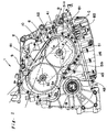
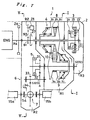
- FIG. 1 is a front view (a view seen in the direction indicated by arrows I-I in FIG. 7) of the continuous speed change mechanism of the vehicular transmission according to the present invention, and it shows the inside of the first room R1 (pulley chamber), which accommodates the drive pulley 8, the driven pulley 9, and the belt 10, which are shown also in FIG. 7.
- S1 through S4 in FIG. 1 correspond with S1 through S4 in FIG. 7.
- the power transmitted from the drive pulley 8 i.e., the first shaft S1, which is shown in the lower right of FIG.
- the above described oil pan 26 is provided under the lower portion of these rooms, i.e., the first and second rooms R1 and R2, the above described oil pan 26 is provided.
- the identical numerals are used for the identical parts, and no further description is given of the parts which have been already explained in reference to FIGS. 6 and 7.
- the following description is based on the transmission being mounted on a vehicle unless otherwise specified, and the rotational direction of the drive pulley 8, the driven pulley 9 and the belt 10 is in the direction indicated by an arrow in the FIG. 1.
- the front and rear direction of the vehicle is perpendicular to the input and output shaft of the continuously variable transmission (i.e., the engine is placed laterally).
- the present invention is not limited to this arrangement and is applicable to the arrangement where the engine is disposed longitudinally along the vehicle.
- expressions "the front of the vehicle” or “the rear of the vehicle” is used to describe the direction.
- the right side of the drawing of FIG. 1 in this embodiment is the front of the vehicle (i.e., the forward direction of the vehicle).
- the lubrication oil to the drive pulley 8, which is mounted on the input shaft 11 (first shaft S1), and to the driven pulley 9, which is mounted on the output shaft 12 (second shaft S2), is supplied through the oil passages which pass through the center of the shafts, respectively, and it is sprayed radially outward in the direction which is perpendicular to the respective shafts by the centrifugal forces generated from the rotation of the respective pulleys and hits the inner wall of the,pulley chamber R1.
- the driven pulley 9 which is shown at the upper left in the drawing, the lubrication oil is also sprayed in a large amount from the bottom of the V groove to the inner face of the belt 10.
- line B is the line drawn on the upper side of the pulleys which line is tangent to the pitch circle of the drive pulley whose pitch radius is at a maximum, which is indicated by ⁇ , and to that of the driven pulley whose pitch radius is at a minimum, which is indicated by ⁇ (i.e., the transmission is at the TOP speed change ratio).
- Line C is the line drawn also on the upper side of the pulleys which line is tangent to the pitch circle of the drive pulley whose pitch radius is at a minimum and to that of the driven pulley whose pitch radius is at a maximum (i.e., the transmission is at the LOW speed change ratio).
- Line A is the line drawn on the upper side of the pulleys which line is tangent to the peripheries of the two pulleys.
- an inlet opening 41 is provided for an oil discharge passage 76 at the portion of the inner wall of the pulley chamber near the drive pulley 8 where the line B meets the inner wall, to lead the oil which is thrown from the belt, directly to the outside of the pulley chamber. Furthermore, this inlet opening 41 is located also at the portion of the inner wall where the line A, which is drawn on the upper side of the two pulleys tangentially to the peripheries of the pulleys, meets the inner wall.
- one inlet opening is provided at the portion of the inner wall which is located at the point of intersection of the line B and the line A.
- the line B is drawn on the upper side of the pulleys tangentially to the pitch circle of the drive pulley whose pitch radius is at a maximum and to that of the driven pulley whose pitch radius is at a minimum while the line A is drawn on the upper side of the two pulleys tangentially to the peripheries of the pulleys as mentioned above.
- two inlet openings may be provided each at a respective point.
- another inlet opening 42 for a discharge oil passage 77 is provided at the portion of the inner wall which faces upward in the pulley chamber, equidistantly to both the pulleys, and the oil flowing down along the inner walls is led to this inlet opening and then through the discharge oil passage 77 to the outside of the pulley chamber.
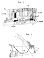
- FIG. 2 is a view seen in the direction indicated by arrows II-II in FIG. 1, i.e., a view of the housing seen from the bottom.
- the inlet openings of the oil discharge passages are darkened in the drawing and are indicated by numerals, and the oil discharge passages are indicated by parenthetical numerals.
- FIG. 3 is a sectional view of the housing seen in the direction indicated by arrows III- III in FIG. 2, and it shows the cross section taken by the plane which is perpendicular to the shafts of the pulleys and which passes through the respective middle points between the stationary pulley halves and the movable pulley halves of the pulleys, to illustrate the oil discharge passage 76, which is located toward the front of the vehicle, the oil discharge passage 77, which is located toward the rear of the vehicle, and the inlet openings 41 and 42 for these oil discharge passages.
- These two drawings show that the oil discharge passages and their inlet openings are provided in the pulley chamber R1, on one side of and near and above the oil pan, toward the front and rear of the vehicle, respectively.
- the direction of the motion of the lubrication oil which departs from the belt at the above mentioned inflection point i.e., the point of the directional change of the belt movement from the straight portion to the arc portion, where the belt starts encircling the respective pulley
- the oil departs from the belt in a direction which is somewhat radially inward with respect to the direction of this imaginary extension line.
- the degree of this discrepancy depends on the viscosity of the lubrication oil, the rotational speed of the belt, and the pitch radii of the pulleys.
- the position of the upper end of the inlet opening 41 of the oil discharge passage which is provided in the direction of the straight portion of the belt is determined appropriately to meet the condition of the belt which is at the TOP speed change ratio (i.e., the condition where the pitch radius of the drive pulley is at a maximum and that of the driven pulley is at a minimum). Also, the position of the lower end of the inlet opening is determined to meet the condition where the pitch radii of the respective pulleys are in the condition opposite to the above description: If the inlet opening determined in this way is too long to threaten the strength of the housing, then a rib can be provided appropriately in the middle of the opening.
- the width of the inlet opening 41 in the direction of the pulley shafts is determined equal to the maximum width of the V-shaped groove measured at the outer periphery of the drive pulley 8, which maximum width is attainable by moving the movable pulley half 8b as far as possible from the stationary pulley half 8a.
- the width of the V-shaped groove of the pulley is greater or equal to the width of the belt, the width of the lubrication oil departing from the belt 10 is smaller than or equal to the width of the inlet opening 41.
- the inlet opening 41 is formed with the width and the length which are determined as described above, most of the lubrication oil departing from the belt is received through the inlet opening into the oil discharge passage. In consideration of the compactness and discharge performance of this inlet opening, it is preferable that the width of the inlet opening be about 3/2 of the maximum width of the V- shaped groove.
- the lubrication oil which is thrown radially from the V- shaped grooves of the drive and driven pulleys 8 and 9 by the respective centrifugal forces hits the inner wall of the pulley chamber R1 and then flows down along the inner wall by the gravitation.
- the part of the lubrication oil which hits the portion of the inner wall just above and the portion located on the right side of the drive pulley 8 in FIG. 1 flows down along the inner wall toward the lower right in the drawing and into the inlet opening 41 of the oil discharge passage which leads to the oil pan 26.
- the lubrication oil which hits the portion of the inner wall of the pulley chamber R1 just above and the portion located on the left side of the driven pulley 9 flows down along the rounded portion of the inner wall located on the left side of the respective pulley.
- the inlet opening 42 is positioned at a midpoint between both the pulleys.
- the width of this inlet opening i.e., the width of the inlet opening in the direction of the pulley shafts
- the width of this inlet opening be equal to or more than the maximum width of the V ⁇ shaped groove at the outer periphery of the driven pulley 9.
- the inlet opening is widened to the side of the movable pulley half 9b.
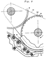
- the stationary pulley half 8a of the drive pulley 8 includes rectangular raised portions 52, which are provided for the measurement of the rotational speed of the drive pulley 8, and a cover 51 is provided under the drive pulley 8 in the pulley chamber R1 to cover these rectangular raised portions 52 partly.
- This cover 51 is, for example, press molded from a sheet metal of steel, aluminum, etc. into a shape which conforms with the drive pulley 8 and the pulley chamber R1; and it is then bolted in the housing.
- the cover 51 is formed to cover the outer periphery of the stationary pulley half 8a, with one end 51a of the cover 51 reaching the inlet opening 41 for the discharge oil passage and the other end 51b being detached from the inner wall of the pulley chamber R1.
- FIG. 5 shows an enlarged view of the vicinity of the end 51b whose surface 51bs facing the inner wall 54 of the pulley chamber R1 is positioned away from the inner wall 54 with a clearance V therebetween.
- an inlet opening 51c is provided for the discharge oil passage, at the bottom portion of the cover 51, the bottom portion being the lowest portion of the cover 51 in the mounted condition.
- FIG. 6 shows the relative positions of the cover 51, the raised portions 52 of the drive pulley 8, and a rotational frequency detector 53, which detects the rotational speed of the drive pulley 8.
- the clearance V between the end surface 51bs and the inner wall 54 of the pulley chamber R1 is determined such that the end 51b of the cover does not interfere with the belt 10, which is disposed around the pulleys.
- the lubrication oil flowing down along the inner walls of the pulley chamber increases in amount, the oil dripping down directly from the part of the inner wall which faces downward increases in amount, the oil which is thrown from the drive pulley 8, the driven pulley 9 and the belt 10 and hitting the part of the inner walls that is located below the inlet openings 41 and 42 of the discharge oil passages 76 and 77 increase in amount, and the oil accumulates at the lower portion of the pulley chamber. Even in such condition, this accumulated oil at the bottom of the pulley chamber cannot be agitated by the drive pulley because of the existence of the cover 51, which constitutes an inner wall and prevents the lubrication oil from flowing into the cover.
- the end surface 51bs of the cover 51 is positioned away from the inner wall 54 of the pulley chamber R1 with a clearance V therebetween as shown in FIGS. 1 and 5.
- the lubrication oil flowing down along this part of the wall is not likely to flow into the cover 51. If the oil flew freely in this direction, which is the opposite direction to the rotational direction of the pulleys, and if the oil flowing down touched the drive pulley 8, then it would cause a substantial resistance or loss in the rotation of the drive pulley 8.
- this construction of the cover 51 which is mounted away from the wall in this direction, restricts the flow of the oil into the cover 51 in a minuscule amount, so the rotational resistance or loss caused from the oil is very small.
- the lubrication oil which is used for the lubrication of the drive pulley 8, the driven pulley 9, the belt 10, etc. in the pulley chamber R1 as well as the hydraulic oil which is used for adjusting the widths of the pulleys is discharged through the inlet opening 41 of the discharge oil passage 76, which is located to the front of the vehicle, through the inlet opening 42 of the discharge oil passage 77, which is located to the rear of the vehicle, and through the inlet opening 44 of the discharge oil passage, which is provided at the bottom of the pulley chamber R1, all the discharge oil passages leading the lubrication oil to the two sides of the oil pan 26 (i.e., close to the side toward the front of the vehicle and to the side toward the rear of the vehicle) in the horizontal direction which is perpendicular to the input and output shafts.
Landscapes
- Engineering & Computer Science (AREA)
- General Engineering & Computer Science (AREA)
- Mechanical Engineering (AREA)
- General Details Of Gearings (AREA)
- Arrangement Of Transmissions (AREA)
- Lubrication Details And Ventilation Of Internal Combustion Engines (AREA)
- Transmissions By Endless Flexible Members (AREA)
Claims (3)
- Fahrzeuggetriebe, umfassend:wobei:eine Getriebevorrichtung mit einer Antriebsriemenscheibe (8), einer Abtriebsriemenscheibe (9) und einem Riemen (10), welcher zur Drehmomentübertragung um diese zwei Riemenscheiben (8, 9) herum angeordnet ist; sowieeine Kammer (R1), welche die Getriebevorrichtung aufnimmt;dadurch gekennzeichnet, dass eine Auslassöffnung (51c) in der Abdeckung (51) am niedrigsten Abschnitt der Abdeckung (51) im montierten Zustand der Abdeckung (51) vorgesehen ist, wobei die Auslassöffnung (51c) dazu ausgebildet ist, Schmieröl aus dem Innenbereich der Abdeckung (51) zu einer Ölwanne (26) auszulassen, welche tiefer als die Kammer (R1) gelegen ist.die Antriebs- (8) oder die Abtriebsriemenscheibe (9) an ihrem Umfang einen erhöhten Abschnitt (52) zur Erfassung von Drehgeschwindigkeiten der Riemenscheiben (8, 9) aufweist;dem Fahrzeuggetriebe Schmieröl zugeführt wird, welches aufgrund ihrer Drehbewegung zumindest teilweise von den Riemenscheiben (8, 9) und dem Riemen (10) zu den Wänden der Kammer (R1) hin weggeschleudert wird;
unddas Fahrzeuggetriebe ferner eine Abdeckung (51) umfasst, welche teilweise einen unteren Umfangsabschnitt entlang des Umfangs jener Riemenscheibe (8, 9) von der Antriebs- (8) oder der Abtriebsriemenscheibe (9) abdeckt, die verglichen mit der jeweils anderen Riemenscheibe (9) in der Kammer (R1) tiefer angeordnet ist, wobei der Umfangsabschnitt den erhöhten Abschnitt (52) umfasst, - Fahrzeuggetriebe nach Anspruch 1, wobei:eine Endfläche (51 bs) der Abdeckung (51), welche Endfläche (51 bs) zu einer Innenwand (54) der Kammer (R1) hinweist, von der Innenwand (54) mit einem dazwischen vorgesehenen Spielraum (V) entfernt angeordnet ist.
- Fahrzeuggetriebe nach Anspruch 1, wobei:jene Riemenscheibe (8), welche an dem unteren Teil der Kammer (R1) angeordnet ist, eine stationäre Riemenscheibenhälfte umfasst, die in axialer Richtung an einer Drehspindel befestigt ist, sowie eine bewegliche Riemenscheibenhälfte umfasst, die zu der stationären Riemenscheibenhälfte hinweist und über die Drehspindel in axialer Richtung bewegbar ist;die stationäre Riemenscheibenhälfte und die bewegliche Riemenscheibenhälfte gemeinsam zwischen sich eine V-Nut bilden, in welcher der Riemen (10) angeordnet ist; und der erhöhte Abschnitt (52) an dem Umfang der stationären Riemenscheibenhälfte vorgesehen ist.
Applications Claiming Priority (2)
| Application Number | Priority Date | Filing Date | Title |
|---|---|---|---|
| JP10253358A JP3061180B2 (ja) | 1998-09-08 | 1998-09-08 | 車両用変速機 |
| JP25335898 | 1998-09-08 |
Publications (3)
| Publication Number | Publication Date |
|---|---|
| EP0985853A2 EP0985853A2 (de) | 2000-03-15 |
| EP0985853A3 EP0985853A3 (de) | 2002-10-09 |
| EP0985853B1 true EP0985853B1 (de) | 2004-05-06 |
Family
ID=17250239
Family Applications (1)
| Application Number | Title | Priority Date | Filing Date |
|---|---|---|---|
| EP99117276A Expired - Lifetime EP0985853B1 (de) | 1998-09-08 | 1999-09-02 | Fahrzeuggetriebe |
Country Status (6)
| Country | Link |
|---|---|
| US (1) | US6238312B1 (de) |
| EP (1) | EP0985853B1 (de) |
| JP (1) | JP3061180B2 (de) |
| CA (1) | CA2281304C (de) |
| DE (1) | DE69916952T2 (de) |
| TW (1) | TW499540B (de) |
Families Citing this family (23)
| Publication number | Priority date | Publication date | Assignee | Title |
|---|---|---|---|---|
| ITTO20010259A1 (it) * | 2000-03-30 | 2002-09-19 | Honda Motor Co Ltd | Sistema di trasmissione della potenza per veicolo di piccole dimensioni. |
| JPWO2003085285A1 (ja) * | 2002-04-08 | 2005-08-11 | ヤマハ発動機株式会社 | エンジン |
| DE10329214B4 (de) * | 2003-06-28 | 2013-05-29 | Zf Friedrichshafen Ag | Sammelbehälter für Spritzöl |
| WO2005008100A1 (ja) * | 2003-07-16 | 2005-01-27 | Yamaha Hatsudoki Kabushiki Kaisha | 鞍乗型車両用エンジン及びそれを備えた鞍乗型車両 |
| JP4074278B2 (ja) | 2004-09-09 | 2008-04-09 | ジヤトコ株式会社 | バッフルプレート排油構造 |
| JP4464233B2 (ja) | 2004-09-21 | 2010-05-19 | ジヤトコ株式会社 | 自動変速機における油分割構造 |
| JP2006090350A (ja) * | 2004-09-21 | 2006-04-06 | Jatco Ltd | バッフルプレート |
| JP2007071254A (ja) * | 2005-09-05 | 2007-03-22 | Yamaha Motor Co Ltd | Vベルト式無段変速機及び鞍乗型車両 |
| JP4939190B2 (ja) * | 2006-11-30 | 2012-05-23 | 本田技研工業株式会社 | 小型車両用パワーユニット |
| DE102011077603B4 (de) * | 2011-06-16 | 2021-06-02 | Zf Friedrichshafen Ag | Getriebeanordnung für ein Schienenfahrzeug |
| CA2901648C (en) * | 2013-02-18 | 2016-05-24 | 9158-7147 Quebec Inc. | Fuel tank, radiator, pedal box assembly, reverse transmission system and electric control module for vehicles |
| US10330189B2 (en) * | 2015-05-21 | 2019-06-25 | Magna Powertrain Of America, Inc. | Active transfer case with splash recovery clutch lubrication system |
| JP6512967B2 (ja) * | 2015-07-02 | 2019-05-15 | 株式会社クボタ | 作業車 |
| JP6384504B2 (ja) * | 2016-03-10 | 2018-09-05 | トヨタ自動車株式会社 | 無段変速機 |
| US9863523B2 (en) * | 2016-03-21 | 2018-01-09 | Textron Innovations Inc. | Continuously variable transmission |
| US10309520B2 (en) * | 2017-02-17 | 2019-06-04 | Ford Global Technologies, Llc | Snubber with scoop feature for automotive transmission |
| JP7294960B2 (ja) * | 2019-08-30 | 2023-06-20 | ファナック株式会社 | 射出成形機 |
| JP7120204B2 (ja) * | 2019-11-05 | 2022-08-17 | トヨタ自動車株式会社 | ベルト式無段変速機 |
| WO2022130768A1 (ja) * | 2020-12-15 | 2022-06-23 | ジヤトコ株式会社 | 装置 |
| WO2023181470A1 (ja) * | 2022-03-23 | 2023-09-28 | ジヤトコ株式会社 | 動力伝達装置 |
| WO2023182450A1 (ja) * | 2022-03-23 | 2023-09-28 | ジヤトコ株式会社 | 動力伝達装置 |
| US11906108B1 (en) * | 2022-07-29 | 2024-02-20 | Deere & Company | Belt trap with integrated tensioner |
| US11953150B2 (en) * | 2022-07-29 | 2024-04-09 | Deere & Company | Belt trap apparatuses |
Family Cites Families (11)
| Publication number | Priority date | Publication date | Assignee | Title |
|---|---|---|---|---|
| US4497285A (en) * | 1981-09-09 | 1985-02-05 | Honda Giken Kogyo Kabushiki Kaisha | Cooling structure for internal combustion engine |
| JP2748479B2 (ja) * | 1988-12-29 | 1998-05-06 | スズキ株式会社 | 車両用無段自動変速機 |
| US5152361A (en) * | 1989-09-22 | 1992-10-06 | Honda Giken Kogyo Kabushiki Kaisha | Motorcycle |
| JPH04118328A (ja) * | 1990-09-06 | 1992-04-20 | Fuji Heavy Ind Ltd | 車両用発進クラッチの制御装置 |
| JPH04258528A (ja) | 1991-02-12 | 1992-09-14 | Honda Motor Co Ltd | 多板クラッチの冷却構造 |
| FR2710958B1 (fr) * | 1993-10-09 | 1998-02-20 | Volkswagen Ag | Variateur de vitesse à réglage progressif avec dispositif de transport d'huile depuis un carter. |
| JPH07174219A (ja) * | 1993-12-20 | 1995-07-11 | Hitachi Ltd | 車両用変速装置 |
| JP3097439B2 (ja) * | 1994-03-17 | 2000-10-10 | 日産自動車株式会社 | 無段変速機の油路構造 |
| BE1008462A3 (nl) * | 1994-06-21 | 1996-05-07 | Vcst Nv | Werkwijze voor het smeren en/of koelen van een transmissie-eenheid bij motorvoertuigen en transmissie-eenheid die deze werkwijze toepast. |
| NL1000087C2 (nl) * | 1995-04-07 | 1996-10-08 | Doornes Transmissie Bv | Continu variabele transmissie. |
| JP2909027B2 (ja) * | 1996-10-08 | 1999-06-23 | 川崎重工業株式会社 | 車両用ベルト式変速機の冷却構造 |
-
1998
- 1998-09-08 JP JP10253358A patent/JP3061180B2/ja not_active Expired - Fee Related
-
1999
- 1999-08-31 CA CA002281304A patent/CA2281304C/en not_active Expired - Fee Related
- 1999-09-01 TW TW088115026A patent/TW499540B/zh active
- 1999-09-02 EP EP99117276A patent/EP0985853B1/de not_active Expired - Lifetime
- 1999-09-02 DE DE69916952T patent/DE69916952T2/de not_active Expired - Lifetime
- 1999-09-07 US US09/391,239 patent/US6238312B1/en not_active Expired - Fee Related
Also Published As
| Publication number | Publication date |
|---|---|
| DE69916952T2 (de) | 2005-05-04 |
| DE69916952D1 (de) | 2004-06-09 |
| EP0985853A3 (de) | 2002-10-09 |
| TW499540B (en) | 2002-08-21 |
| CA2281304A1 (en) | 2000-03-08 |
| EP0985853A2 (de) | 2000-03-15 |
| CA2281304C (en) | 2008-07-22 |
| US6238312B1 (en) | 2001-05-29 |
| JP3061180B2 (ja) | 2000-07-10 |
| JP2000085389A (ja) | 2000-03-28 |
Similar Documents
| Publication | Publication Date | Title |
|---|---|---|
| EP0985853B1 (de) | Fahrzeuggetriebe | |
| EP0974775B1 (de) | Gehäuse für stufenloses Fahrzeuggetriebe | |
| EP1635090B1 (de) | Ölabsaugeeinrichtung | |
| US8261883B2 (en) | Vehicle power transmission device | |
| US8366577B2 (en) | Power transmission device | |
| US8328668B2 (en) | Vehicle power transmission device | |
| JP2748479B2 (ja) | 車両用無段自動変速機 | |
| GB2166816A (en) | Transmission lubrication | |
| EP0984206B1 (de) | Fahrzeuggetriebe | |
| US7140995B2 (en) | Gear drive | |
| JP5480873B2 (ja) | 車両用変速機 | |
| JP3748680B2 (ja) | 無段変速機の潤滑構造 | |
| JP3853964B2 (ja) | パワーユニットにおける無段変速機の潤滑構造 | |
| US20020019279A1 (en) | Continuously variable transmission oil pressure control device | |
| JP7762079B2 (ja) | オイル循環構造 | |
| KR100692740B1 (ko) | 수동 변속기의 오일 가이드 구조 | |
| JP4116318B2 (ja) | オイルポンプの潤滑装置 | |
| KR100309336B1 (ko) | 수동변속기의윤활구조 | |
| KR100309910B1 (ko) | 자동차변속기의윤활장치 | |
| JP4325267B2 (ja) | 潤滑構造 | |
| JPH0612281Y2 (ja) | 無段変速機の潤滑装置 | |
| JPH0658390A (ja) | 無段変速機の潤滑装置 | |
| KR19980041911U (ko) | 자동차용 트랜스밋션 오일 가이드 구조 | |
| JPH0512831U (ja) | 無段変速機の潤滑装置 | |
| KR19980049834A (ko) | 차량용 무단 변속장치 |
Legal Events
| Date | Code | Title | Description |
|---|---|---|---|
| PUAI | Public reference made under article 153(3) epc to a published international application that has entered the european phase |
Free format text: ORIGINAL CODE: 0009012 |
|
| AK | Designated contracting states |
Kind code of ref document: A2 Designated state(s): AT BE CH CY DE DK ES FI FR GB GR IE IT LI LU MC NL PT SE |
|
| AX | Request for extension of the european patent |
Free format text: AL;LT;LV;MK;RO;SI |
|
| PUAL | Search report despatched |
Free format text: ORIGINAL CODE: 0009013 |
|
| AK | Designated contracting states |
Kind code of ref document: A3 Designated state(s): AT BE CH CY DE DK ES FI FR GB GR IE IT LI LU MC NL PT SE |
|
| AX | Request for extension of the european patent |
Free format text: AL;LT;LV;MK;RO;SI |
|
| 17P | Request for examination filed |
Effective date: 20021030 |
|
| 17Q | First examination report despatched |
Effective date: 20030214 |
|
| AKX | Designation fees paid |
Designated state(s): DE GB |
|
| GRAP | Despatch of communication of intention to grant a patent |
Free format text: ORIGINAL CODE: EPIDOSNIGR1 |
|
| GRAS | Grant fee paid |
Free format text: ORIGINAL CODE: EPIDOSNIGR3 |
|
| GRAA | (expected) grant |
Free format text: ORIGINAL CODE: 0009210 |
|
| AK | Designated contracting states |
Kind code of ref document: B1 Designated state(s): DE GB |
|
| REG | Reference to a national code |
Ref country code: GB Ref legal event code: FG4D |
|
| REF | Corresponds to: |
Ref document number: 69916952 Country of ref document: DE Date of ref document: 20040609 Kind code of ref document: P |
|
| REG | Reference to a national code |
Ref country code: IE Ref legal event code: FG4D |
|
| PLBE | No opposition filed within time limit |
Free format text: ORIGINAL CODE: 0009261 |
|
| STAA | Information on the status of an ep patent application or granted ep patent |
Free format text: STATUS: NO OPPOSITION FILED WITHIN TIME LIMIT |
|
| 26N | No opposition filed |
Effective date: 20050208 |
|
| REG | Reference to a national code |
Ref country code: IE Ref legal event code: MM4A |
|
| PGFP | Annual fee paid to national office [announced via postgrant information from national office to epo] |
Ref country code: GB Payment date: 20100901 Year of fee payment: 12 |
|
| PGFP | Annual fee paid to national office [announced via postgrant information from national office to epo] |
Ref country code: DE Payment date: 20100825 Year of fee payment: 12 |
|
| GBPC | Gb: european patent ceased through non-payment of renewal fee |
Effective date: 20110902 |
|
| REG | Reference to a national code |
Ref country code: DE Ref legal event code: R119 Ref document number: 69916952 Country of ref document: DE Effective date: 20120403 |
|
| PG25 | Lapsed in a contracting state [announced via postgrant information from national office to epo] |
Ref country code: DE Free format text: LAPSE BECAUSE OF NON-PAYMENT OF DUE FEES Effective date: 20120403 |
|
| PG25 | Lapsed in a contracting state [announced via postgrant information from national office to epo] |
Ref country code: GB Free format text: LAPSE BECAUSE OF NON-PAYMENT OF DUE FEES Effective date: 20110902 |