EP0986245B1 - Schattierungskorrekturvorrichtung und eine Bildlesevorrichtung mit Benutzung der Schattierungskorrekturvorrichtung - Google Patents
Schattierungskorrekturvorrichtung und eine Bildlesevorrichtung mit Benutzung der Schattierungskorrekturvorrichtung Download PDFInfo
- Publication number
- EP0986245B1 EP0986245B1 EP99117027.5A EP99117027A EP0986245B1 EP 0986245 B1 EP0986245 B1 EP 0986245B1 EP 99117027 A EP99117027 A EP 99117027A EP 0986245 B1 EP0986245 B1 EP 0986245B1
- Authority
- EP
- European Patent Office
- Prior art keywords
- shading
- correction
- reading
- reference plate
- white reference
- Prior art date
- Legal status (The legal status is an assumption and is not a legal conclusion. Google has not performed a legal analysis and makes no representation as to the accuracy of the status listed.)
- Expired - Lifetime
Links
- 238000003705 background correction Methods 0.000 title claims description 113
- 238000000034 method Methods 0.000 claims description 30
- 238000012935 Averaging Methods 0.000 claims description 8
- 239000000428 dust Substances 0.000 description 21
- 239000002245 particle Substances 0.000 description 21
- 230000000694 effects Effects 0.000 description 8
- 230000006870 function Effects 0.000 description 7
- 238000010586 diagram Methods 0.000 description 6
- 230000003287 optical effect Effects 0.000 description 5
- 238000012545 processing Methods 0.000 description 2
- 230000003321 amplification Effects 0.000 description 1
- 230000015556 catabolic process Effects 0.000 description 1
- 238000006731 degradation reaction Methods 0.000 description 1
- 230000001419 dependent effect Effects 0.000 description 1
- 238000011161 development Methods 0.000 description 1
- 230000018109 developmental process Effects 0.000 description 1
- 238000012986 modification Methods 0.000 description 1
- 230000004048 modification Effects 0.000 description 1
- 238000003199 nucleic acid amplification method Methods 0.000 description 1
Images


Classifications
-
- H—ELECTRICITY
- H04—ELECTRIC COMMUNICATION TECHNIQUE
- H04N—PICTORIAL COMMUNICATION, e.g. TELEVISION
- H04N1/00—Scanning, transmission or reproduction of documents or the like, e.g. facsimile transmission; Details thereof
- H04N1/40—Picture signal circuits
- H04N1/407—Control or modification of tonal gradation or of extreme levels, e.g. background level
- H04N1/4076—Control or modification of tonal gradation or of extreme levels, e.g. background level dependent on references outside the picture
Definitions
- the present invention relates to a shading correction apparatus for correcting shading of image data obtained by reading an image, using shading data obtained by reading a white reference plate, and an image read apparatus.
- Document GB-A-2 303 757 discloses a method and apparatus for performing shading correction on a pixel array.
- Each of a plurality of adjacent rows are sequentially selected in the array, and each of a predetermined plurality of adjacent columns are sequentially selected in the array.
- the median brightness value of three pixels in the selected column and three adjacent rows centered on the selected row is determined.
- the median value of three of the median brightness values previously determined for the selected row and three adjacent columns centered on the selected column is determined.
- the determination result is stored as the shading corrected brightness value for the selected row and column.
- US patent 4,691,240 A discloses a shading correction apparatus and method for performing shading correction of data according to the preamble of claims 1 and 10, using shading data obtained by reading a white reference panel by a photo-sensor, comprising an objective lens system being defocused by an optical path length changing member.
- US patent 5,099,341 A discloses a shading correction apparatus for performing shading correction of data using shading data obtained by reading shading correction plates by an image scanner.
- Fig. 8 is a view schematically showing the internal arrangement of an image read apparatus such as a copying machine using a CCD.
- an image read apparatus such as a copying machine using a CCD.
- an original 1 placed on an original table 2 is irradiated with a lamp 3.
- the light reflected by the original is incident on a CCD sensor unit 8 through mirrors 4, 5, and 6 and a lens unit 7.
- the CCD sensor unit 8 reads the original image.
- shading due to the characteristics of the mechanical and optical systems need be corrected.
- the shading is corrected using shading data obtained by reading a white reference plate 9 shown in Fig. 8 by the CCD sensor unit 8 having a plurality of pixels.
- shading data is read by the CCD sensor unit 8 a plurality of number of times at the fixed position of the white reference plate 9.
- the average value of shading data is obtained in units of pixels of the CCD sensor unit 8.
- a shading correction coefficient (shading correction data) at each pixel position is calculated by comparing the average value with the target shading value (ideal value).
- image data obtained from a corresponding pixel of the CCD sensor unit 8 is multiplied by the shading correction coefficient, thereby correcting shading.
- Fig. 9 is a graph for explaining the relationship between the average value of shading data obtained by reading the white reference plate 9 and the data value after shading correction.
- the broken line indicates the ideal value (level) of the shading value (data) when the white plate is read.
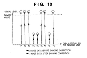
- Fig. 10 shows an example of image data (bold arrows) obtained by reading the original and data (thin arrows) obtained by shading-correcting the image data using the obtained shading correction coefficients.
- Fig. 11 is a graph showing the average value of shading data and shading-corrected data at each pixel position when an obstacle is present at a position corresponding to the pixel position P 5 on the white reference plate.
- data supposed to be obtained has a signal level indicated by the circle of broken line.
- data having a signal level much lower than that indicated by the circle of broken line is obtained due to the obstacle.
- a shading correction coefficient much larger than the necessary shading correction coefficient is calculated to correct the data at the pixel position P 5 to the target value.
- Fig. 12 is a graph showing a case wherein image data (the same as in Fig. 10 ) read from the original is shading-corrected using a shading correction coefficient obtained on the basis of the shading data shown in Fig. 11 .
- image data the same as in Fig. 10
- the data is multiplied by the shading correction coefficient larger than the necessary shading correction coefficient. For this reason, the signal level becomes higher than the signal level (circle of broken line) supposed to be obtained.
- a method has been proposed in which shading data is read at a plurality of positions shifted on the white reference plate in the sub-scanning direction, and the average value of shading data is obtained in units of pixels, thereby eliminating the influence of degradation in light source or obstacles on the optical path.
- Fig. 13 shows shading data read at a plurality of positions on the white reference plate and the average value of shading data at the respective pixel positions on the CCD sensor unit 8 when an obstacle is present at a position corresponding to the pixel position P 5 on the white reference plate at a certain read position.
- Fig. 14 is a graph showing a case wherein the image data (the same as in Fig. 10 ) read from the original is shading-corrected using a shading correction coefficient obtained on the basis of these average values.
- Fig. 15 shows values obtained by averaging shading data read by the method described with reference to Fig. 13 when a large obstacle is present on the white reference plate.
- Fig. 16 is a graph showing image data obtained by shading correction using the average values.
- the present invention has been made in consideration of the above situation, and has as its object of the present invention to provide a shading correction apparatus and method capable of minimizing the influence of a dust particle on a white reference plate and always performing optimum shading correction, and an image read apparatus using the shading correction apparatus.
- a shading correction apparatus as set forth in claim 1, a shading correction apparatus as set forth in claim 2, a shading correction apparatus as set forth in claim 3, an image read apparatus as set forth in claim 7, a shading correction method as set forth in claim 8, a shading correction method as set forth in claim 9, a shading correction method as set forth in claim 10, and a storage medium as set forth in claim 14.
- Fig. 1 is a block diagram showing an arrangement of a shading correction apparatus according to the first embodiment of the present invention.
- reference numeral 101 denotes a CCD linear image sensor.
- An amplification circuit (AMP) 102 amplifies the output from the image sensor 101.
- An analog/digital converter (A/D) 103 converts the amplified analog signal into a digital signal.
- Shading memory 104 stores image data (shading data) obtained by reading a white reference plate (not shown) as a digital signal.
- a division circuit 105 divides the image data converted into a digital signal by shading data stored in the memory 104.
- a multiplication circuit 106 multiplies the divided data by a predetermined value and outputs shading-corrected image data.
- a comparison circuit 107 compares the minimum value (min) of the data stored in the memory 104 with a predetermined value.
- a CPU 108 performs various control operations and has memory 109 for storing minimum value data from the memory 104.
- a motor 110 moves the read position in the sub-scanning direction.
- a motor control circuit 111 controls driving the motor 110.
- the CPU 108 has a shading data acquisition section for scanning the white reference plate with the image sensor 101 in the main scanning direction and sub-scanning direction to obtain shading data, and a shading data acquisition section for scanning the white reference plate in only the main scanning direction to obtain shading data.
- the CPU 108 also has a selection section for selecting one of the two shading data acquisition sections.
- the white reference plate read mode digital data obtained by A/D-converting the output from the image sensor 101 is stored in the memory 104.
- the minimum value in the memory 104 is stored in the memory 109 of the CPU 108.
- the A/D-converted output is directly input to the division circuit 105 without being stored in the memory 104, and divided by the shading data stored in the memory 104.
- the multiplication circuit 106 multiplies the data by a predetermined value.
- the CPU 108 sets the predetermined value as an ideal value obtained when the white reference plate is read.
- the image data obtained by reading the original is shading-corrected by the division and multiplication.
- the white reference plate is read once by pre-scanning in the main scanning direction.
- the minimum value of the shading data obtained at that time is stored in the memory 109 of the CPU 108.
- shading data are read at different sub-scanning positions in the main scanning direction within the readable region (control region) on the white reference plate. Shading correction is performed using the value obtained by adding and averaging the read shading data in the sub-scanning direction.
- shading data read by pre-scanning is read at another sub-scanning position within the readable region on the white reference plate, and shading correction is performed using the read value.
- the two operations are automatically switched.
- the minimum value is equal to or smaller than the predetermined value
- the user is caused to input a sub-scanning shading data read position.
- Pre-scanning can be performed at any position within the readable region on the white reference plate, and in the first embodiment, the shading data is read at a position near the center of the white reference plate in the main scanning direction in the pre-scanning.
- Fig. 2 is a flow chart showing the control operation of the shading correction apparatus according to the first embodiment of the present invention. Specifically, Fig. 2 shows shading data acquisition control. This control operation is performed by the CPU 108 in accordance with a control program stored in advance.
- step S11 a minimum value SHmin of shading data read by pre-scanning is read out from the memory 109.
- step S12 it is determined whether the readout minimum value SHmin is larger than a predetermined value k. If YES in step S12, the flow advances to step S13.
- the motor control circuit 111 controls the motor 110 to move the read position in the sub-scanning direction within the readable region of the white reference plate, so shading data are read at a plurality of positions. The read shading data are added and averaged.
- step S12 If NO in step S12, the flow advances to step S14.
- the white reference plate is read at the designated position by controlling the motor 110 on the basis of the designation, thereby obtaining shading data (step S15).
- the method of reading the readable region on the white reference plate and performing shading correction upon adding and averaging the shading data is very effective for a small dust particle on the white reference plate.
- the decrease in average value can be minimized by using the average value of shading data.
- small means that the number of data influenced by the dust particle is very small with respect to the number of shading data read during movement in the sub-scanning direction.
- one of two different methods i.e., the method of reading shading data at a plurality of positions in the sub-scanning direction and using the average value of shading data for shading correction and the method of reading shading data at a designated position and directly using the read value for shading correction is automatically selected.
- the influence of dust particles on the white reference plate can be reduced.
- shading data is directly stored in the memory 104.
- the same effect as described above can be obtained even when a shading correction coefficient is stored in the memory 104 and compared with a predetermined value, and the data acquisition method used for shading correction is switched in accordance with the comparison result.
- Fig. 3 is a block diagram showing an arrangement of a shading correction apparatus according to the second embodiment of the present invention.
- the same reference numerals as in Fig. 1 denote the same part in Fig. 3 .
- a counter 201 counts comparison result output from a comparison circuit 107.
- a white reference plate (not shown) is to be read
- digital data obtained by A/D-converting the output from an image sensor 101 is stored in memory 104.
- the minimum value in the memory 104 is also stored in memory 109 of a CPU 108.
- the A/D-converted output is directly input to a division circuit 105 without being stored in the memory 104, and divided by the shading data stored in the memory 104.
- a multiplication circuit 106 multiplies the data by a predetermined value.
- the CPU 108 sets the predetermined value as an ideal value obtained when the white reference plate is read.
- the image data obtained by reading the original is shading-corrected by the division and multiplication.
- pre-scanning is performed before shading data to be used for shading correction is read.
- the white reference plate is read at a plurality of sub-scanning positions (e.g., 5 to 10 positions) in the main scanning direction, and the minimum value of the shading data obtained at that time is stored in the memory 109 of the CPU 108 every time the shading data is read in the main scanning direction.
- the counter 201 counts the number of shading data having minimum values equal to or smaller than a predetermined value, which are read by pre-scanning and stored in the memory 109.
- shading data is read at sub-scanning positions in the main scanning direction within the same region on the white reference plate as the pre-scanning. Shading correction is performed using a value obtained by adding and averaging the read shading data in the sub-scanning direction. If the count value exceeds the predetermined value, shading data is read at another position within the readable region on the white reference plate. Shading correction is performed using this read value. The two operations are automatically switched. When the count value exceeds the predetermined value, the user is caused to input a sub-scanning shading data read position. Pre-scanning can be performed at any position within the readable region on the white reference plate, and in the second embodiment, the shading data is read at a position near the center of the white reference plate in the main scanning direction in the pre-scanning.
- Fig. 4 is a flow chart showing the control operation of the shading correction apparatus according to the second embodiment of the present invention. Especially, Fig. 4 shows shading data acquisition control. This control operation is performed by the CPU 108 in accordance with a control program stored in advance.
- step S21 a minimum value SHmin of shading data read by pre-scanning is read out from the memory 109.
- step S22 it is determined whether the readout minimum value SHmin is larger than a predetermined value k. If NO in step S22, the flow advances to step S23 to increment a counter value m by one. Then, the flow advances to step S24. If YES in step S22, the flow directly advances to step S24 without incrementing the counter value.
- step S24 it is determined whether a predetermined number (the number of sub-scanning positions where shading data is read by pre-scanning) of minimum values SHmin are read. If NO in step S24, the flow returns to step S21 to repeat processing in steps S21 to S24.
- step S24 the flow advances to step S25 to determine whether the counter value m is smaller than a predetermined value T. If YES in step S25, the flow advances to step S26.
- the motor control circuit 111 controls the motor 110 to move the read position in the sub-scanning direction within the readable region of the white reference plate, so shading data are read at a plurality of positions. The read shading data are added and averaged.
- step S25 If NO in step S25, the flow advances to step S27.
- the white reference plate is read at the designated position by controlling the motor 110 on the basis of the designation, thereby obtaining shading data (step S28).
- the second embodiment provides the following effect in addition to the effect of the first embodiment.
- the average value of the shading data is used to correct shading. If the number of shading data influenced by the dust particles beyond a predetermined level is larger than the predetermined value, shading data read at a position selected by the user, which has no influence of the dust particles, is directly used for shading correction. For this reason, the accuracy of shading can be controlled.
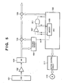
- Fig. 5 is a block diagram showing the arrangement of a shading correction apparatus according to the third embodiment of the present invention.
- the same reference numerals as in Figs. 1 and 3 denote the same parts in Fig. 5 .
- an AND circuit 301 calculates the AND condition between the output of a comparison result from a comparison circuit 107 and the previous comparison result stored in memory 109 of a CPU 108.
- pre-scanning is performed before shading data to be used for shading correction is read.
- the white reference plate is read at a plurality of sub-scanning positions in the main scanning direction, and the minimum value of the shading data obtained at that time is stored in the memory 109 of the CPU 108 every time the shading data is read in the main scanning direction.
- the result of comparison between a minimum value stored in the memory 109 and a predetermined value are input to the AND circuit 301.
- shading data is read by scanning at another predetermined position within the readable region on the white reference plate, and the read value is used for shading correction.
- shading data are read at sub-scanning positions in the main scanning direction within the same region on the white reference plate as the pre-scanning, and a value obtained by adding and averaging the read shading data is used to correct shading.
- Pre-scanning can be performed at any position within the readable region on the white reference plate, and in the third embodiment, the shading data is read at a position near the center of the white reference plate in the main scanning direction in the pre-scanning.
- the operation is switched for two consecutive shading data.
- n comparison results from the comparison circuit 107 may be stored.
- n consecutive shading data are equal to or smaller than the predetermined value
- shading data is read at another position within the readable region on the white reference plate, and the read value is used for shading correction.
- the two operations are automatically switched.
- the count value exceeds the predetermined value, the user is caused to input a sub-scanning shading data read position.
- Fig. 6 is a flow chart showing the control operation of the shading correction apparatus according to the third embodiment of the present invention.
- Fig. 6 shows shading data acquisition control. This control operation is performed by the CPU 108 in accordance with a control program stored in advance.
- step S31 a minimum value SHmin of shading data read by pre-scanning is read out from the memory 109.
- step S32 it is determined whether the readout minimum value SHmin is larger than a predetermined value k. If YES in step S32, the flow advances to step S33.
- step S34 the flow advances to step S34 to read out, from the memory 109, the comparison result between the minimum value SHmin of the previously read shading data and the predetermined value k. If the minimum value SHmin is larger than the predetermined value k, the flow advances to step S33.
- a motor control circuit 111 controls a motor 110 to move the read position in the sub-scanning direction within the readable region of the white reference plate, so shading data is read at a plurality of positions. The read shading data are added and averaged.
- step S34 If it is determined in step S34 that the comparison result between the minimum value SHmin of the previous shading data and the predetermined value k indicates that the predetermined value k is equal to or larger than the minimum value SHmin, the flow advances to step S35. After the user designates a shading data read position, the white reference plate is read at the designated position by controlling the motor 110 on the basis of the designation, thereby obtaining shading data (step S36).
- the third embodiment provides the following effect in addition to the effect of the first embodiment.
- the method of acquiring data for shading correction can be changed to adjust the accuracy of shading.
- a shading correction apparatus having the arrangement described in the first embodiment with reference to Fig. 1 is used.
- the fourth embodiment is different from the first embodiment in the following point.
- the minimum value of shading data read by pre-scanning is equal to or smaller than a predetermined value
- shading data are read at a plurality of positions while scanning a predetermined region in the sub-scanning direction.
- the minimum values of shading data obtained at the respective positions are stored in memory 104 and compared with each other. Shading data having the largest minimum value are determined as data to be used for shading correction.
- the remaining operations are the same as those described in the first embodiment with reference to Fig. 2 .
- Fig. 7 is a flow chart showing the control operation of the shading correction apparatus according to the fourth embodiment. Especially, Fig. 7 shows shading data acquisition control. This control operation is performed by a CPU 108 in accordance with a control program stored in advance.
- step S41 a minimum value SHmin of previously read shading data is read out from a memory 109.
- step S42 it is determined whether the readout minimum value SHmin is larger than a predetermined value k. If YES in step S42, the flow advances to step S43.
- a motor control circuit 111 controls a motor 110 to move the read position in the sub-scanning direction within the readable region of the white reference plate, so shading data are read at a plurality of positions. The read shading data are added and averaged.
- step S44 The motor control circuit 111 controls the motor 110 to move the read position in the sub-scanning direction within the readable region of the white reference plate, so shading data are read at a plurality of positions and stored in the memory 104.
- the minimum values SHmin at the respective positions are stored in the memory 109.
- step S45 optimum shading data is selected from the read shading data. More specifically, the largest minimum value is selected from the minimum values SHmin stored in the memory 109, and shading data having the selected minimum value SHmin is determined as data to be used for shading correction.
- the fourth embodiment provides the following effect in addition to the effect of the first embodiment.
- data with the minimum influence of the dust particle is selected from a plurality of shading data and used for shading correction. For this reason, the accuracy of shading correction can be increased.
- the operation of the fourth embodiment can be applied to the second and third embodiments. More specifically, the operation in steps S44 and S45 in Fig. 7 can be performed in place of steps S27 and S28 in Fig. 4 or steps S35 and S36 in Fig. 6 .
- the shading correction apparatus has been described.
- the shading correction apparatus of the present invention can be used for an apparatus such as a copying machine or a scanner which reads and processes an image.
- a signal is read using the CCD linear image sensor 101.
- the present invention is not limited to this.
- An area sensor may be used instead of the linear image sensor. This can make the processing speed higher than that in use of the linear image sensor.
- the shading correction apparatuses described in the first to fourth embodiments can be applied to various image read apparatuses using a CCD, such as the conventional copying machine described with reference to Fig. 8 or a film scanner.
- the object of the present invention can also be achieved by providing a storage medium storing program codes for performing the aforesaid processes to a computer system or apparatus (e.g., a personal computer), reading the program codes, by a CPU or MPU of the computer system or apparatus, from the storage medium, then executing the program.
- a computer system or apparatus e.g., a personal computer
- the program codes read from the storage medium realize the functions according to the embodiments, and the storage medium storing the program codes constitutes the invention.
- the storage medium such as a floppy disk, a hard disk, an optical disk, a magneto-optical disk, CD-ROM, CD-R, a magnetic tape, a non-volatile type memory card, and ROM can be used for providing the program codes.
- the present invention includes a case where an OS (Operating System) or the like working on the computer performs a part or entire processes in accordance with designations of the program codes and realizes functions according to the above embodiments.
- OS Operating System
- the present invention also includes a case where, after the program codes read from the storage medium are written in a function expansion card which is inserted into the computer or in a memory provided in a function expansion unit which is connected to the computer, CPU or the like contained in the function expansion card or unit performs a part or entire processes in accordance with designations of the program codes and realizes functions of the above embodiments.
- the storage medium stores program codes corresponding to the flow charts in Figs. 2 , 4 , 6 , and 7 described in the first to fourth embodiments.
Landscapes
- Engineering & Computer Science (AREA)
- Multimedia (AREA)
- Signal Processing (AREA)
- Facsimile Image Signal Circuits (AREA)
- Image Input (AREA)
- Facsimile Scanning Arrangements (AREA)
Claims (14)
- Schattierungskorrekturvorrichtung zum Durchführen einer Schattierungskorrektur von Daten, die durch Lesen eines Originals (1) erhalten werden, unter Verwendung von Schattierungsdaten, die durch Lesen einer weißen Referenztafel (9) durch einen Bildsensor (101) erhalten werden, gekennzeichnet durch:eine Auswahleinrichtung (104, 107, 108, 109) zum Auswählen einer ersten Korrekturdatenbeschaffungseinrichtung (108) zum Beschaffen von Korrekturdaten, die für eine Schattierungskorrektur zu verwenden sind, unter Verwendung von Schattierungsdaten, die durch Lesen der weißen Referenztafel (9) in eine erste Richtung an einer Vielzahl von Positionen in eine zweite Richtung senkrecht zu der ersten Richtung erhalten werden, oder einer zweiten Korrekturdatenbeschaffungseinrichtung (108) zum Beschaffen von Korrekturdaten, die für eine Schattierungskorrektur zu verwenden sind, unter Verwendung von Schattierungsdaten, die durch Lesen der weißen Referenztafel (9) in die erste Richtung an einer einzelnen Position in die zweite Richtung erhalten werden, wobeiwenn ein Minimalwert von Schattierungsdaten, die durch eine Vorabtastung in die erste Richtung an einer einzelnen Position in die zweite Richtung erhalten werden, einen vorbestimmten Wert übersteigt, die Auswahleinrichtung (108) dazu konfiguriert ist, die erste Korrekturdatenbeschaffungseinrichtung (108) auszuwählen, und wenn der Minimalwert nicht mehr als der vorbestimmte Wert ist, die Auswahleinrichtung dazu konfiguriert ist, die zweite Korrekturdatenbeschaffungseinrichtung (108) auszuwählen.
- Schattierungskorrekturvorrichtung zum Durchführen einer Schattierungskorrektur von Daten, die durch Lesen eines Originals (1) erhalten werden, unter Verwendung von Schattierungsdaten, die durch Lesen einer weißen Referenztafel (9) durch einen Bildsensor (101) erhalten werden, gekennzeichnet durch
eine Auswahleinrichtung (104, 107, 108, 109) zum Auswählen einer ersten Korrekturdatenbeschaffungseinrichtung (108) zum Erhalten von Korrekturdaten, die für eine Schattierungskorrektur zu verwenden sind, unter Verwendung von Schattierungsdaten, die durch Lesen der weißen Referenztafel (9) in eine erste Richtung an einer Vielzahl von Positionen in eine zweite Richtung senkrecht zu der ersten Richtung erhalten werden, oder einer zweiten Korrekturdatenbeschaffungseinrichtung (108) zum Erhalten von Korrekturdaten, die für eine Schattierungskorrektur zu verwenden sind, unter Verwendung von Schattierungsdaten, die durch Lesen der weißen Referenztafel (9) in die erste Richtung an einer einzelnen Position in die zweite Richtung erhalten werden, wobei
wenn eine Anzahl, wie oft ein Minimalwert von Schattierungsdaten, die durch Durchführen einer Vorabtastung in die erste Richtung an jeder von unterschiedlichen Positionen in die zweite Richtung erhalten werden, nicht mehr als ein erster vorbestimmter Wert ist, nicht mehr als ein zweiter vorbestimmter Wert ist, die Auswahleinrichtung (108) dazu konfiguriert ist, die erste Korrekturdatenbeschaffungseinrichtung (108) auszuwählen, und wenn die Anzahl den zweiten vorbestimmten Wert übersteigt, die Auswahleinrichtung dazu konfiguriert ist, die zweite Korrekturdatenbeschaffungseinrichtung (108) auszuwählen. - Schattierungskorrekturvorrichtung zum Durchführen einer Schattierungskorrektur von Daten, die durch Lesen eines Originals (1) erhalten werden, unter Verwendung von Schattierungsdaten, die durch Lesen einer weißen Referenztafel (9) durch einen Bildsensor (101) erhalten werden, gekennzeichnet durch:eine Auswahleinrichtung (104, 107, 108, 109) zum Auswählen einer ersten Korrekturdatenbeschaffungseinrichtung (108) zum Beschaffen von Korrekturdaten, die für eine Schattierungskorrektur zu verwenden sind, unter Verwendung von Schattierungsdaten, die durch Lesen der weißen Referenztafel (9) in eine erste Richtung an einer Vielzahl von Positionen in eine zweite Richtung senkrecht zu der ersten Richtung erhalten werden, oder einer zweiten Korrekturdatenbeschaffungseinrichtung (108) zum Erhalten von Korrekturdaten, die für eine Schattierungskorrektur zu verwenden sind, unter Verwendung von Schattierungsdaten, die durch Lesen der weißen Referenztafel (9) in die erste Richtung an einer einzelnen Position in die zweite Richtung erhalten werden, wobeiwenn eine Anzahl von aufeinanderfolgenden Malen, wie oft ein Minimalwert von Schattierungsdaten, die durch Durchführen einer Vorabtastung in die erste Richtung an jeder von unterschiedlichen Positionen in die zweite Richtung erhalten werden, nicht mehr als ein erster vorbestimmter Wert ist, nicht mehr als ein zweiter vorbestimmter Wert ist, die Auswahleinrichtung (108) dazu konfiguriert ist, die erste Korrekturdatenbeschaffungseinrichtung (108) auszuwählen, und wenn die Anzahl von aufeinanderfolgenden Malen den zweiten vorbestimmten Wert übersteigt, die Auswahleinrichtung dazu konfiguriert ist, die zweite Korrekturdatenbeschaffungseinrichtung (108) auszuwählen.
- Schattierungskorrekturvorrichtung gemäß einem der Ansprüche 1 bis 3, wobei die erste Korrekturdatenbeschaffungseinrichtung (108) dazu konfiguriert ist, die Korrekturdaten durch Addieren und Mitteln, in die zweite Richtung, der Schattierungsdaten, die durch Lesen in die erste und zweite Richtung erhalten werden, zu erhalten.
- Schattierungskorrekturvorrichtung gemäß einem der Ansprüche 1 bis 4, wobei die zweite Korrekturdatenbeschaffungseinrichtung (108) dazu konfiguriert ist, den Bildsensor (101) zu steuern, um die Schattierungsdaten an einer designierten Position innerhalb eines vorbestimmten Bereichs der weißen Referenztafel (9) zu lesen.
- Schattierungskorrekturvorrichtung gemäß einem der Ansprüche 1 bis 4, wobei die zweite Korrekturdatenbeschaffungseinrichtung (108) dazu konfiguriert ist, Schattierungsdaten, die durch Lesen in die erste Richtung erhalten werden, basierend auf einer vorbestimmten Bedingung von den Schattierungsdaten, die durch Lesen der weißen Referenztafel (9) in die erste und zweite Richtung erhalten werden, auszuwählen.
- Bildlesevorrichtung zum Durchführen einer Schattierungskorrektur von Daten, die durch Lesen eines Originals (1) erhalten werden, unter Verwendung von Schattierungsdaten, die durch Lesen einer weißen Referenztafel (9) durch einen Bildsensor (101) erhalten werden, wobei die Vorrichtung eine Schattierungskorrekturvorrichtung gemäß einem der Ansprüche 1 bis 6 umfasst.
- Schattierungskorrekturverfahren zum Durchführen einer Schattierungskorrektur von Daten, die durch Lesen eines Originals (1) erhalten werden, unter Verwendung von Schattierungsdaten, die durch Lesen einer weißen Referenztafel (9) durch einen Bildsensor (101) erhalten werden, gekennzeichnet durch:einen Auswahlschritt (S12, S25, S32, S34, S42) zum Auswählen eines ersten Korrekturdatenbeschaffungsschritts (S13, S26, S33, S43) des Erhaltens von Korrekturdaten, die für eine Schattierungskorrektur zu verwenden sind, unter Verwendung von Schattierungsdaten, die durch Lesen der weißen Referenztafel (9) in eine erste Richtung an einer Vielzahl von Positionen in eine zweite Richtung senkrecht zu der ersten Richtung erhalten werden, oder eines zweiten Korrekturdatenbeschaffungsschritts (S14, S15, S27, S28, S35, S36, S44, S45) des Erhaltens von Korrekturdaten, die für eine Schattierungskorrektur zu verwenden sind, unter Verwendung von Schattierungsdaten, die durch Lesen der weißen Referenztafel (9) in die erste Richtung an einer einzelnen Position in die zweite Richtung erhalten werden, undeinen Vorabtastschritt (S12, S42) des Vorabtastens der weißen Referenztafel (9) in die erste Richtung,wobei, in dem Auswahlschritt, wenn ein Minimalwert von Schattierungsdaten, die durch Vorabtasten in die erste Richtung an einer einzelnen Position in die zweite Richtung erhalten werden, einen vorbestimmten Wert übersteigt, der erste Korrekturdatenbeschaffungsschritt ausgewählt wird, und wenn ein Minimalwert nicht mehr als der vorbestimmte Wert ist, der zweite Korrekturdatenbeschaffungsschritt ausgewählt wird.
- Schattierungskorrekturverfahren des Durchführens einer Schattierungskorrektur von Daten, die durch Lesen eines Originals (1) erhalten werden, unter Verwendung von Schattierungsdaten, die durch Lesen einer weißen Referenztafel (9) durch einen Bildsensor (101) erhalten werden, gekennzeichnet durch:einen Auswahlschritt (S12, S25 S32, S34, S42) zum Auswählen eines ersten Korrekturdatenbeschaffungsschritts (S13, S26, S33, S43) des Erhaltens von Korrekturdaten, die für eine Schattierungskorrektur zu verwenden sind, unter Verwendung von Schattierungsdaten, die durch Lesen der weißen Referenztafel (9) in eine erste Richtung an einer Vielzahl von Positionen in eine zweite Richtung senkrecht zu der ersten Richtung erhalten werden, oder eines zweiten Korrekturdatenbeschaffungsschritts (S14, S15, S27, S28, S35, S36, S44, S45) des Erhaltens von Korrekturdaten, die für eine Schattierungskorrektur zu verwenden sind, unter Verwendung von Schattierungsdaten, die durch Lesen der weißen Referenztafel (9) in die erste Richtung an einer einzelnen Position in die zweite Richtung erhalten werden, undeinen Vorabtastschritt des Vorabtastens der weißen Referenztafel (9) in die erste Richtung an jeder von verschiedenen Positionen in die zweite Richtung,wobei, in dem Auswahlschritt (S25), wenn die Anzahl, wie oft ein Minimalwert von Schattierungsdaten, die durch Durchführen einer Vorabtastung in die erste Richtung erhalten werden, nicht mehr als ein erster vorbestimmter Wert ist, nicht mehr als ein zweiter vorbestimmter Wert ist, die erste Korrekturdatenbeschaffungsschritt ausgewählt wird, und wenn eine Anzahl den zweiten vorbestimmten Wert übersteigt, der zweite Korrekturdatenbeschaffungsschritt ausgewählt wird.
- Schattierungskorrekturverfahren des Durchführens einer Schattierungskorrektur von Daten, die durch Lesen eines Originals (1) erhalten werden, unter Verwendung von Schattierungsdaten, die durch Lesen einer weißen Referenztafel (9) durch einen Bildsensor (101) erhalten werden, gekennzeichnet durch:einen Auswahlschritt (S12, S25, S32, S34, S42) des Auswählens eines ersten Korrekturdatenbeschaffungsschritts (S13, S26, S33, S43) des Beschaffens von Korrekturdaten, die für eine Schattierungskorrektur zu verwenden sind, unter Verwendung von Schattierungsdaten, die durch Lesen der weißen Referenztafel (9) in eine erste Richtung an einer Vielzahl von Positionen in eine zweite Richtung senkrecht zu der ersten Richtung erhalten werden, und eines zweiten Korrekturdatenbeschaffungsschritts (S14, S15, S27, S28, S35, S36, S44, S45) des Beschaffens von Korrekturdaten, die für eine Schattierungskorrektur zu verwenden sind, unter Verwendung von Schattierungsdaten, die durch Lesen der weißen Referenztafel (9) in die erste Richtung an einer einzelnen Position in die zweite Richtung erhalten werden, undeinen Vorabtastschritt des Vorabtastens der weißen Referenztafel (9) in die erste Richtung an jeder von verschiedenen Positionen in die zweite Richtung,wobei in dem Auswahlschritt (S32, S34), wenn eine Anzahl von aufeinanderfolgenden Malen, wenn ein Minimalwert von Schattierungsdaten, der durch eine Vorabtastung in die erste Richtung erhalten wird, nicht mehr als ein erster vorbestimmter Wert ist, nicht mehr als ein zweiter vorbestimmter Wert ist, der erste Korrekturdatenbeschaffungsschritt ausgewählt wird, und wenn die Anzahl von aufeinanderfolgenden Malen den zweiten vorbestimmten Wert übersteigt, der zweite Korrekturdatenbeschaffungsschritt ausgewählt wird.
- Schattierungskorrekturverfahren gemäß einem der Ansprüche 8 bis 10, wobei, in dem ersten Korrekturdatenbeschaffungsschritt (S13, S26, S33, S43) die Korrekturdaten durch Addieren und Mitteln, in die zweite Richtung, der Schattierungsdaten, die durch Lesen in die erste und zweite Richtung erhalten werden, erhalten werden.
- Schattierungskorrekturverfahren gemäß einem der Ansprüche 8 bis 11, wobei, in dem zweiten Korrekturdatenbeschaffungsschritt (S14, S15, S27, S28, S35, S36), der Bildsensor (101) gesteuert wird, um die Schattierungsdaten an einer designierten Position innerhalb eines vorbestimmten Bereichs der weißen Referenztafel (9) zu lesen.
- Schattierungskorrekturverfahren gemäß einem der Ansprüche 8 bis 11, wobei, in dem zweiten Korrekturdatenbeschaffungsschritt (S44, S45) Schattierungsdaten, die durch Lesen in die erste Richtung erhalten werden, basierend auf einer vorbestimmten Bedingung von den Schattierungsdaten, die durch Lesen der weißen Referenztafel in die erste und zweite Richtung erhalten werden, ausgewählt werden.
- Speichermedium, das Anweisungen zum Steuern des Prozessors speichert, um das Verfahren gemäß einem der Ansprüche 8 bis 13 auszuführen.
Applications Claiming Priority (2)
| Application Number | Priority Date | Filing Date | Title |
|---|---|---|---|
| JP24539898 | 1998-08-31 | ||
| JP24539898A JP3554199B2 (ja) | 1998-08-31 | 1998-08-31 | シェーディング補正装置、シェーディング補正方法及び画像読み取り装置 |
Publications (3)
| Publication Number | Publication Date |
|---|---|
| EP0986245A2 EP0986245A2 (de) | 2000-03-15 |
| EP0986245A3 EP0986245A3 (de) | 2002-06-26 |
| EP0986245B1 true EP0986245B1 (de) | 2014-05-07 |
Family
ID=17133069
Family Applications (1)
| Application Number | Title | Priority Date | Filing Date |
|---|---|---|---|
| EP99117027.5A Expired - Lifetime EP0986245B1 (de) | 1998-08-31 | 1999-08-30 | Schattierungskorrekturvorrichtung und eine Bildlesevorrichtung mit Benutzung der Schattierungskorrekturvorrichtung |
Country Status (3)
| Country | Link |
|---|---|
| US (1) | US6704457B1 (de) |
| EP (1) | EP0986245B1 (de) |
| JP (1) | JP3554199B2 (de) |
Families Citing this family (12)
| Publication number | Priority date | Publication date | Assignee | Title |
|---|---|---|---|---|
| US6518587B2 (en) * | 2000-05-17 | 2003-02-11 | Heidelberger Druckmaschinen Ag | Detection and correction of defects from scanner calibration references |
| JP4110715B2 (ja) * | 2000-07-11 | 2008-07-02 | コニカミノルタビジネステクノロジーズ株式会社 | 画像処理装置 |
| US7119932B2 (en) * | 2000-07-19 | 2006-10-10 | Canon Kabushiki Kaisha | Image scanning system and method |
| US7161712B2 (en) * | 2001-04-20 | 2007-01-09 | Ricoh Company, Ltd. | Apparatus for forming images with proper gamma correction |
| JP2003037718A (ja) * | 2001-07-23 | 2003-02-07 | Ricoh Co Ltd | 画像読み取り装置及び画像形成装置 |
| KR100464545B1 (ko) * | 2003-04-15 | 2005-01-03 | 삼성전자주식회사 | 화상 스캐닝 장치 및 그의 쉐이딩 보정 방법 |
| JP2004357190A (ja) * | 2003-05-30 | 2004-12-16 | Ricoh Co Ltd | 画像読取装置 |
| JP4388327B2 (ja) * | 2003-08-25 | 2009-12-24 | オリンパス株式会社 | 顕微鏡像撮像装置及び顕微鏡像撮像方法 |
| JP4539424B2 (ja) * | 2005-04-28 | 2010-09-08 | ブラザー工業株式会社 | 画像読取装置 |
| JP2008211710A (ja) * | 2007-02-28 | 2008-09-11 | Brother Ind Ltd | 通信装置 |
| DE102014112002A1 (de) | 2014-08-21 | 2016-02-25 | Carl Zeiss Microscopy Gmbh | Verfahren zur Abbildung einer Probe mittels eines Mikroskops und Mikroskop |
| JP7230542B2 (ja) * | 2019-01-31 | 2023-03-01 | ブラザー工業株式会社 | 読取装置 |
Family Cites Families (8)
| Publication number | Priority date | Publication date | Assignee | Title |
|---|---|---|---|---|
| JPS61227481A (ja) * | 1985-03-30 | 1986-10-09 | Dainippon Screen Mfg Co Ltd | 画像入力装置における補正用基準デ−タ取込方法 |
| JPH0335233A (ja) * | 1989-06-30 | 1991-02-15 | Toshiba Corp | 画像形成装置 |
| US5214518A (en) * | 1989-12-22 | 1993-05-25 | Fuji Xerox Co., Ltd. | Multiple value image input equipment |
| US5371613A (en) * | 1991-02-22 | 1994-12-06 | Canon Kabushiki Kaisha | Image reading apparatus |
| JPH099063A (ja) * | 1995-06-21 | 1997-01-10 | Brother Ind Ltd | 画像読み取り転送方法及びその転送システム |
| KR100193795B1 (ko) * | 1995-07-21 | 1999-06-15 | 윤종용 | 쉐이딩 보정회로 및 방법 |
| JP3569059B2 (ja) | 1995-11-24 | 2004-09-22 | 株式会社リコー | 画像読取装置 |
| JPH1023254A (ja) * | 1996-07-04 | 1998-01-23 | Matsushita Electric Ind Co Ltd | 画像読み取り装置 |
-
1998
- 1998-08-31 JP JP24539898A patent/JP3554199B2/ja not_active Expired - Fee Related
-
1999
- 1999-08-30 EP EP99117027.5A patent/EP0986245B1/de not_active Expired - Lifetime
- 1999-08-30 US US09/385,709 patent/US6704457B1/en not_active Expired - Lifetime
Also Published As
| Publication number | Publication date |
|---|---|
| JP3554199B2 (ja) | 2004-08-18 |
| JP2000078372A (ja) | 2000-03-14 |
| EP0986245A2 (de) | 2000-03-15 |
| EP0986245A3 (de) | 2002-06-26 |
| US6704457B1 (en) | 2004-03-09 |
Similar Documents
| Publication | Publication Date | Title |
|---|---|---|
| US6882754B2 (en) | Image signal processor with adaptive noise reduction and an image signal processing method therefor | |
| EP0986245B1 (de) | Schattierungskorrekturvorrichtung und eine Bildlesevorrichtung mit Benutzung der Schattierungskorrekturvorrichtung | |
| US7755664B2 (en) | Image pickup apparatus | |
| US4860118A (en) | Image signal processing apparatus with edge emphasis and variable magnification | |
| EP0866608A2 (de) | Verfahren zur Korrektur der Luminanzgradation innerhalb eines Bildaufnahmegerätes | |
| US20020036697A1 (en) | Imaging apparatus | |
| US7358999B2 (en) | Focus sensing apparatus, focus sensing method using phase-differential detection and computer-readable storage medium therefor | |
| US7221394B2 (en) | Digital camera | |
| US20020003908A1 (en) | Image reading apparatus and shading correction data acquiring method | |
| EP0211070B1 (de) | Dynamische verstärkungsregulieranlage für einen bildabtaster | |
| US5887085A (en) | Image processing device | |
| JPH04363967A (ja) | 原稿読取り装置 | |
| EP0863656A2 (de) | Bildabtastvorrichtung und Verfahren zum Abtasten von Bildern | |
| EP1058448B1 (de) | Bildverarbeitungsgerät | |
| US20040012700A1 (en) | Image processing device, image processing program, and digital camera | |
| EP2445199A1 (de) | Bildaufnahmevorrichtung | |
| JP3564050B2 (ja) | カメラ、焦点調節装置、焦点調節方法、焦点調節プログラムを供給する媒体 | |
| US7542081B2 (en) | Image input apparatus | |
| US5748800A (en) | Image reading device that selectively performs edge contrast adjustment | |
| EP0808057B1 (de) | Verfahren und Vorrichtung zum Korrigieren eines Ausgangssignals eines Zeilensensors | |
| EP1185078B1 (de) | Verfahren zur Erzeugung schwarzer Referenzdaten und Bildlesevorrichtung | |
| JP3701094B2 (ja) | 画像読取装置 | |
| JP2001346012A (ja) | 画像読取装置及び画像信号の調整方法 | |
| JP4188114B2 (ja) | シェーディング補正回路 | |
| JP3382481B2 (ja) | 撮像装置 |
Legal Events
| Date | Code | Title | Description |
|---|---|---|---|
| PUAI | Public reference made under article 153(3) epc to a published international application that has entered the european phase |
Free format text: ORIGINAL CODE: 0009012 |
|
| AK | Designated contracting states |
Kind code of ref document: A2 Designated state(s): AT BE CH CY DE DK ES FI FR GB GR IE IT LI LU MC NL PT SE |
|
| AX | Request for extension of the european patent |
Free format text: AL;LT;LV;MK;RO;SI |
|
| PUAL | Search report despatched |
Free format text: ORIGINAL CODE: 0009013 |
|
| AK | Designated contracting states |
Kind code of ref document: A3 Designated state(s): AT BE CH CY DE DK ES FI FR GB GR IE IT LI LU MC NL PT SE |
|
| AX | Request for extension of the european patent |
Free format text: AL;LT;LV;MK;RO;SI |
|
| RIC1 | Information provided on ipc code assigned before grant |
Free format text: 7H 04N 1/407 A, 7H 04N 1/401 B |
|
| 17P | Request for examination filed |
Effective date: 20021107 |
|
| AKX | Designation fees paid |
Designated state(s): DE FR GB IT NL |
|
| GRAP | Despatch of communication of intention to grant a patent |
Free format text: ORIGINAL CODE: EPIDOSNIGR1 |
|
| INTG | Intention to grant announced |
Effective date: 20131125 |
|
| GRAS | Grant fee paid |
Free format text: ORIGINAL CODE: EPIDOSNIGR3 |
|
| GRAA | (expected) grant |
Free format text: ORIGINAL CODE: 0009210 |
|
| AK | Designated contracting states |
Kind code of ref document: B1 Designated state(s): DE FR GB IT NL |
|
| REG | Reference to a national code |
Ref country code: GB Ref legal event code: FG4D |
|
| REG | Reference to a national code |
Ref country code: DE Ref legal event code: R096 Ref document number: 69945083 Country of ref document: DE Effective date: 20140618 |
|
| REG | Reference to a national code |
Ref country code: NL Ref legal event code: T3 |
|
| PGFP | Annual fee paid to national office [announced via postgrant information from national office to epo] |
Ref country code: NL Payment date: 20140716 Year of fee payment: 16 |
|
| PGFP | Annual fee paid to national office [announced via postgrant information from national office to epo] |
Ref country code: FR Payment date: 20140519 Year of fee payment: 16 |
|
| PGFP | Annual fee paid to national office [announced via postgrant information from national office to epo] |
Ref country code: IT Payment date: 20140514 Year of fee payment: 16 |
|
| REG | Reference to a national code |
Ref country code: DE Ref legal event code: R097 Ref document number: 69945083 Country of ref document: DE |
|
| REG | Reference to a national code |
Ref country code: DE Ref legal event code: R119 Ref document number: 69945083 Country of ref document: DE |
|
| PLBE | No opposition filed within time limit |
Free format text: ORIGINAL CODE: 0009261 |
|
| STAA | Information on the status of an ep patent application or granted ep patent |
Free format text: STATUS: NO OPPOSITION FILED WITHIN TIME LIMIT |
|
| 26N | No opposition filed |
Effective date: 20150210 |
|
| GBPC | Gb: european patent ceased through non-payment of renewal fee |
Effective date: 20140830 |
|
| REG | Reference to a national code |
Ref country code: DE Ref legal event code: R097 Ref document number: 69945083 Country of ref document: DE Effective date: 20150210 |
|
| REG | Reference to a national code |
Ref country code: DE Ref legal event code: R119 Ref document number: 69945083 Country of ref document: DE Effective date: 20150303 |
|
| PG25 | Lapsed in a contracting state [announced via postgrant information from national office to epo] |
Ref country code: DE Free format text: LAPSE BECAUSE OF NON-PAYMENT OF DUE FEES Effective date: 20150303 Ref country code: GB Free format text: LAPSE BECAUSE OF NON-PAYMENT OF DUE FEES Effective date: 20140830 |
|
| PG25 | Lapsed in a contracting state [announced via postgrant information from national office to epo] |
Ref country code: IT Free format text: LAPSE BECAUSE OF NON-PAYMENT OF DUE FEES Effective date: 20150830 |
|
| REG | Reference to a national code |
Ref country code: NL Ref legal event code: MM Effective date: 20150901 |
|
| REG | Reference to a national code |
Ref country code: FR Ref legal event code: ST Effective date: 20160429 |
|
| PG25 | Lapsed in a contracting state [announced via postgrant information from national office to epo] |
Ref country code: NL Free format text: LAPSE BECAUSE OF NON-PAYMENT OF DUE FEES Effective date: 20150901 |
|
| PG25 | Lapsed in a contracting state [announced via postgrant information from national office to epo] |
Ref country code: FR Free format text: LAPSE BECAUSE OF NON-PAYMENT OF DUE FEES Effective date: 20150831 |