EP0987389A1 - Télécommande plate notamment pour véhicule automobile - Google Patents
Télécommande plate notamment pour véhicule automobile Download PDFInfo
- Publication number
- EP0987389A1 EP0987389A1 EP99115645A EP99115645A EP0987389A1 EP 0987389 A1 EP0987389 A1 EP 0987389A1 EP 99115645 A EP99115645 A EP 99115645A EP 99115645 A EP99115645 A EP 99115645A EP 0987389 A1 EP0987389 A1 EP 0987389A1
- Authority
- EP
- European Patent Office
- Prior art keywords
- housing
- remote control
- case
- control according
- head
- Prior art date
- Legal status (The legal status is an assumption and is not a legal conclusion. Google has not performed a legal analysis and makes no representation as to the accuracy of the status listed.)
- Granted
Links
- 239000002184 metal Substances 0.000 claims description 9
- 229910052751 metal Inorganic materials 0.000 claims description 9
- 230000000295 complement effect Effects 0.000 claims description 4
- 229920003023 plastic Polymers 0.000 claims description 4
- 239000004033 plastic Substances 0.000 claims description 4
- 230000002093 peripheral effect Effects 0.000 claims description 3
- 230000008859 change Effects 0.000 claims description 2
- 238000009434 installation Methods 0.000 claims description 2
- 238000012550 audit Methods 0.000 description 2
- 241000270295 Serpentes Species 0.000 description 1
- 240000008042 Zea mays Species 0.000 description 1
- 230000006378 damage Effects 0.000 description 1
- 230000000694 effects Effects 0.000 description 1
- 230000000670 limiting effect Effects 0.000 description 1
- 238000000034 method Methods 0.000 description 1
- 238000005192 partition Methods 0.000 description 1
- 238000003825 pressing Methods 0.000 description 1
- 230000002441 reversible effect Effects 0.000 description 1
- 238000006748 scratching Methods 0.000 description 1
- 230000002393 scratching effect Effects 0.000 description 1
- 238000000926 separation method Methods 0.000 description 1
- 238000002604 ultrasonography Methods 0.000 description 1
Images



Classifications
-
- E—FIXED CONSTRUCTIONS
- E05—LOCKS; KEYS; WINDOW OR DOOR FITTINGS; SAFES
- E05B—LOCKS; ACCESSORIES THEREFOR; HANDCUFFS
- E05B19/00—Keys; Accessories therefor
- E05B19/0082—Keys or shanks being removably stored in a larger object, e.g. a remote control or a key fob
-
- A—HUMAN NECESSITIES
- A45—HAND OR TRAVELLING ARTICLES
- A45C—PURSES; LUGGAGE; HAND CARRIED BAGS
- A45C11/00—Receptacles for purposes not provided for in groups A45C1/00-A45C9/00
- A45C11/32—Bags or wallets for holding keys
- A45C11/325—Spare-key holders
- A45C11/326—Card-like holders
-
- E—FIXED CONSTRUCTIONS
- E05—LOCKS; KEYS; WINDOW OR DOOR FITTINGS; SAFES
- E05B—LOCKS; ACCESSORIES THEREFOR; HANDCUFFS
- E05B19/00—Keys; Accessories therefor
- E05B19/04—Construction of the bow or head of the key; Attaching the bow to the shank
- E05B19/046—Construction of the bow or head of the key; Attaching the bow to the shank the shank being slidingly mounted on the bow, e.g. for storage
-
- G—PHYSICS
- G07—CHECKING-DEVICES
- G07C—TIME OR ATTENDANCE REGISTERS; REGISTERING OR INDICATING THE WORKING OF MACHINES; GENERATING RANDOM NUMBERS; VOTING OR LOTTERY APPARATUS; ARRANGEMENTS, SYSTEMS OR APPARATUS FOR CHECKING NOT PROVIDED FOR ELSEWHERE
- G07C9/00—Individual registration on entry or exit
- G07C9/00174—Electronically operated locks; Circuits therefor; Nonmechanical keys therefor, e.g. passive or active electrical keys or other data carriers without mechanical keys
- G07C9/00944—Details of construction or manufacture
-
- H—ELECTRICITY
- H01—ELECTRIC ELEMENTS
- H01M—PROCESSES OR MEANS, e.g. BATTERIES, FOR THE DIRECT CONVERSION OF CHEMICAL ENERGY INTO ELECTRICAL ENERGY
- H01M50/00—Constructional details or processes of manufacture of the non-active parts of electrochemical cells other than fuel cells, e.g. hybrid cells
- H01M50/20—Mountings; Secondary casings or frames; Racks, modules or packs; Suspension devices; Shock absorbers; Transport or carrying devices; Holders
- H01M50/204—Racks, modules or packs for multiple batteries or multiple cells
- H01M50/207—Racks, modules or packs for multiple batteries or multiple cells characterised by their shape
- H01M50/216—Racks, modules or packs for multiple batteries or multiple cells characterised by their shape adapted for button or coin cells
-
- A—HUMAN NECESSITIES
- A45—HAND OR TRAVELLING ARTICLES
- A45C—PURSES; LUGGAGE; HAND CARRIED BAGS
- A45C11/00—Receptacles for purposes not provided for in groups A45C1/00-A45C9/00
- A45C11/32—Bags or wallets for holding keys
- A45C2011/322—Sheath-like bags for protecting a key-blade or for receiving a key
-
- G—PHYSICS
- G07—CHECKING-DEVICES
- G07C—TIME OR ATTENDANCE REGISTERS; REGISTERING OR INDICATING THE WORKING OF MACHINES; GENERATING RANDOM NUMBERS; VOTING OR LOTTERY APPARATUS; ARRANGEMENTS, SYSTEMS OR APPARATUS FOR CHECKING NOT PROVIDED FOR ELSEWHERE
- G07C9/00—Individual registration on entry or exit
- G07C9/00174—Electronically operated locks; Circuits therefor; Nonmechanical keys therefor, e.g. passive or active electrical keys or other data carriers without mechanical keys
- G07C9/00944—Details of construction or manufacture
- G07C2009/00952—Electronic keys comprising a mechanical key within their housing, e.g. extractable or retractable emergency key
-
- Y—GENERAL TAGGING OF NEW TECHNOLOGICAL DEVELOPMENTS; GENERAL TAGGING OF CROSS-SECTIONAL TECHNOLOGIES SPANNING OVER SEVERAL SECTIONS OF THE IPC; TECHNICAL SUBJECTS COVERED BY FORMER USPC CROSS-REFERENCE ART COLLECTIONS [XRACs] AND DIGESTS
- Y02—TECHNOLOGIES OR APPLICATIONS FOR MITIGATION OR ADAPTATION AGAINST CLIMATE CHANGE
- Y02E—REDUCTION OF GREENHOUSE GAS [GHG] EMISSIONS, RELATED TO ENERGY GENERATION, TRANSMISSION OR DISTRIBUTION
- Y02E60/00—Enabling technologies; Technologies with a potential or indirect contribution to GHG emissions mitigation
- Y02E60/10—Energy storage using batteries
Definitions
- the present invention relates to remote controls, especially for a motor vehicle. We know that, for greater user comfort,
- An object of the invention is to propose a remote control to flat case, for example of a format similar to that of a standard smart card.
- Another object of the invention is to propose a remote control of this type in which the different functions techniques associated with the remote control are integrated so ergonomic in the housing thereof, being practically not externally noticeable, so that said remote control is mainly for the user like a card.
- the invention proposes a remote control in particular of motor vehicle, characterized in that it is capable of being also used as a badge, its case presenting a general flat parallelepiped shape, said housing comprising in its thickness a housing in which is mounted a pivoting case intended to receive at least one flat battery, this housing being closed by a removable head whose shape extends that of the rest of the case and is complementary to it, the case being such that when the head is removed relative to the rest of the case, it can be rotated to be taken out at least partially compared to the rest of the case, so that the user can then access the battery to change it.
- the remote control forming a card illustrated in FIGS. 1 and 2 is in the form of a flat form case rectangular parallelepiped, of a format close to that of a standard smart card.
- this case referenced by 1, has a thickness of a few millimeters and a rectangular outline of a width and length similar to that of a card chip, but slightly lower than these, so that said case can be slipped into a wallet pocket, despite its thickness.
- This case 1 mainly consists of two half-shells plates 1a, 1b attached to each other and welded for example by friction or ultrasound.
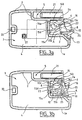
- These two flat half-shells 1a, 1b have extra thicknesses 2 which, as we can see more particularly in Figures 3a, 3b and 4a, 4b, border continuously the bottoms of the two half-shells 1a and 1b on their two lengths and over one of their width and also extend inside the housing 1 to define walls which, with the edges of the half-shells 1a, 1b, delimit inside the housing 1 on the one hand a housing waterproof 3 in which is disposed a card 4 carrying the electronics of the remote control and on the other hand two housings 5 and 6 which one receives a metal insert 7, the other a flat battery 8.
- the two housings 5 and 6 are both open at the level from the end where the two half-shellsla, 1b are not closed by a thicker border.
- the housing 5 which receives the metal insert 7 is a elongated housing which extends along one of the edges in the length of the housing 1 and which constitutes for the insert 7 a sheath in which said insert is stored.
- Insert 7 is a flat metal blade elongated parallelepiped which has engravings interior ("snake key” engravings according to the terminology of the skilled person) and whose straight edges allow the guiding said insert 7 in its sheath 5. This insert 7 is intended to constitute a mechanical emergency key for cases where the remote control is faulty.
- Said insert 7 ends with a head 9 (FIGS. 2, 4a, 7) which is in the same plastic as the housing 1 of the remote control.
- This head 9 has a shape which is complementary to that of the two half-shells 1a and 1b added one on the other and which, when the insert 7 is in place in the sheath that defines the housing 5, closes the housing 1 so that the user does not see slots 5 and 6.
- the head 9 has an elongated shape which has a width which decreases from the corner of the case 1, where the case that constitutes the housing 5 opens out to its end opposite.
- said head 9 has a protrusion 10 which is a bulge which projects towards the inside of the case 1 and which cooperates with a hard point that constitutes an additional thickness 11 on the inner face of one of the two half-shells 1a, 1b to prevent said head 9 does not deviate from the rest of case 1 otherwise only under the effect of an effort exerted by the user.
- the head 9 is also extended at the same level end by a lug 17 which is intended to constitute a tool allowing the operator to release lock covers on the doors of his vehicle.
- This lug 17 is also made of plastic so as to Avoid any risk of scratching the sheet metal of the car when the user uses this lug.
- the housing 6 is juxtaposed with the housing 5, of which it is separated by a wall 2a which extends in the length of the case and which delimits (in part) both housing 5 and the housing 6.
- This housing 6 has a generally shaped section square and integrates, with the flat stack 8, on the one hand of the blades which provide the electrical connection with said cell 8 and on the other hand mechanical means which allow to retract said flat battery 8 in said housing 6 or take it out by audit report.
- Mechanical means which allow the stack 8 to be retracted in housing 6 or take it out with respect to said housing have a flat case 12 in which the battery 8 is received.
- This flat case 12 is pivotally mounted around an axis A which is journalled between the two half-shells 1a, 1b and which is perpendicular to them, this axis A being located in said housing 6 in the vicinity of the opening of said housing 6, at the opposite of the wall 2a which delimits said housing 6 and the housing 5.
- said case 12 can pivot between a position where it is partially out of the housing 6 and a position where it is stored inside said housing 6.
- Said case 12 has on one side an opening by which the battery 8 is placed in said case 12, when this one is in its position where it is partly out of the housing 6, the outline of said case 12 being such that when the battery 8 is in place in said case 12, it partially exceeds said case 12, which allows the operator to grasp it when the case 12 is tilted outside the housing 6.
- This case 12 is in one piece with a part 13 forming lever which extends through the opening of the housing 6 when it is in its retracted position inside said housing, this part 13 being intended to be grasped by the operator to allow him to rotate said case 12 from one position to another.
- the head 9 of the insert 7 has a recess wherein the lever portion 13 is received when said insert 7 is in place in its sheath 5 and that said head 9 closes box 1.
- axis A is forced into place in the housing 6 once the two half-shells 1a, 1b are welded to each other.
- the bottoms of the two half-shells 1a, 1b present in the vicinity of the opening of the housing 6 a slight inclination which facilitates this installation.
- a rib 25 extends over the entire periphery of the part which constitutes the case 12 and the lever 13, between said case 12 and said lever 13. This rib 25 can receive a seal which seals the housing 6 tightly, when the case 12 and the battery 8 are in their retracted position.
- the blades ensuring the electrical connection between the terminals of stack 8 to card 4 have been referenced by 14 and 15. They both extend in the bottom of the half-shell 1a.
- the blade 14 has a foot 14a which crosses the wall which separates the housing 6 and the housing 3 and which is parallel to the bottom of the half-shell 1a, a portion 14b which extends said part 14a and which extends along the wall which separates the housings 5 and 6, parallel to this and a part 14c which extends part 14b by being folded in V with respect to this one.
- Part 14c constitutes an elastic tongue intended to be in contact with the edge of stack 8, i.e. with the positive terminal of this one.
- This tongue 15d is intended to come elastically into contact with the underside of stack 8, i.e. with the negative terminal of it.
- the stack 8 presses progressively on this tab 15d when said stack 8 and the case 12 are folded down in their retracted position at inside the housing 6.
- the case 12 presents on its face opposite the half-shell 1 has a recess 27 (FIG. 3a) whose shape allows the case 12 to pass over said tongue 15d without crushing it, said tongue extending then in the thickness of said case 12.
- the command button is a button unique which allows to control the locking and unlocking the doors.
- a larger number of buttons command 18 can be provided for for example command separately the door lock function, the function unlocking mode or hands-free operation.
- the half-shell 1b present at the level of the button (s) slimming control which gives it a domed shape.
- the hollow which corresponds to this dome receives a metal cup 19 which, when an operator presses on domes 18, comes into contact by its edge peripheral on an annular contact track presented by the card 4, while its central part comes into contact with a central pad carried by said card 4 (pad 22 in the figures 3a, 4a and 4b), this central stud being connected to the circuit that carries said card 4 on its face opposite the bottom of the half-shell 1b via a ⁇ via ⁇ crossing said card 2.
- the card 4 carries an electroluminescent diode allowing the user to check the correct operation of his remote control.
- This diode is not externally visible when it is not activated, but is visible by transparency through the bottom of the half-shell 1b when it is lit, the wall of said half-shell being thinned for this purpose. to the right of said diode (thickness less than 2/10 e of mm, for example).
- the card can carry an identification tab 21 which fits into the wall that forms the bottom of the half-shell 1a.
- the wall which constitutes the bottom of said half-shell 1a for this purpose has a longitudinal opening which extends in the length of the housing 5, the edges of said wall being shaped like a dovetail, so that said opening and said edges define a slide for the tongue 21.
- This tongue 21 is externally visible. She is intended to allow the user to recognize his own remote control, by color or reference sign particular carried by said tongue 21.
- the light-emitting diode is advantageously ahead of (x) push button (s) so that when the operator enters the card, it does not come to hide said diode.
- buttons (s) 18 By pressing button (s) 18, the user controls locking / unlocking the doors, locking / unlocking the trunk, switching to hands-free operation, etc.
- Said electronic card 4 incorporates means forming transponder which are then interrogated by the reader for provide a computer in the vehicle with a code authorizing the unlocking of the immobilizer function.
- the remote control when for one reason or another, the remote control is broken and the user needs to serve as the insert which constitutes the mechanical emergency key, it pulls the head 9 relative to the rest of said housing for disengage said insert 7 relative to its sheath 5.
Landscapes
- Chemical & Material Sciences (AREA)
- Chemical Kinetics & Catalysis (AREA)
- Electrochemistry (AREA)
- General Chemical & Material Sciences (AREA)
- Engineering & Computer Science (AREA)
- Manufacturing & Machinery (AREA)
- Physics & Mathematics (AREA)
- General Physics & Mathematics (AREA)
- Lock And Its Accessories (AREA)
Abstract
Description
- le boítier comporte le long d'un de ses bords dans sa longueur un logement formant fourreau destiné à recevoir un insert métallique qui peut être utilisé comme clé mécanique de secours ;
- la tête qui ferme le logement de la pile ferme également le logement de l'insert ;
- ladite tête est solidaire de l'insert ;
- la tête présente une protubérance qui est un renflement qui s'étend en saillie vers l'intérieur du boítier et qui coopère avec un point dur que constitue au moins une surépaisseur sur la face intérieure du boítier ;
- la tête présente un ergot apte à constituer un outil permettant à un utilisateur de dégager des caches de serrure, notamment sur des portières de véhicule ;
- cet ergot est en matière plastique ;
- l'étui pivotant est d'une pièce avec une partie formant levier qui est destinée à être saisie et à permettre de faire pivoter ledit étui de sa position escamotée à sa position où il est sorti du logement ;
- la tête présente un évidement dans lequel la partie formant levier est reçue lorsque ladite tête est en place sur le reste du boítier ;
- la paroi qui définit le logement dans lequel est disposé l'étui pivotant présente un dégagement recevant la partie formant levier lorsque l'étui est basculé dans sa position où il est sorti ;
- la pièce qui constitue l'étui et le levier présente entre ces deux parties une nervure apte à recevoir un joint d'étanchéité ;
- les parois du boítier présentent au voisinage de l'ouverture du logement dans lequel est disposé l'étui pivotant une légère inclinaison qui facilite la mise en place, à force, de l'étui et de son axe ;
- le logement comporte deux lames destinées à assurer la connexion électrique entre la pile et l'électronique de la télécommande, l'une de ces lames s'étendant latéralement dans le logement et étant destinée à venir en contact avec la tranche de la pile, l'autre de ces lames s'étendant à partir du fond du boítier et étant destinée à venir en contact avec une face de la pile ;
- la première lame présente un pli qui définit un point dur qui permet de verrouiller élastiquement la pile et l'étui lorsqu'ils sont basculés dans leur position escamotée à l'intérieur du logement ;
- l'étui pivotant présente un évidement dans lequel la deuxième lame s'étend lorsque l'étui est pivoté d'une position à une autre ;
- les pieds des lames sont surmoulés dans une surépaisseur qui sépare de façon étanche le logement de la pile d'un logement dans lequel est disposée l'électronique de la télécommande ;
- le boítier présente une forme en dôme au niveau d'une ou plusieurs zones formant bouton de commande ;
- le boítier reçoit à l'intérieur de cette forme en dôme une coupelle métallique qui, lorsqu'un opérateur appuie sur ladite forme en dôme, vient en contact par son bord périphérique sur une piste annulaire de contact et par sa partie centrale sur un plot central de contact ;
- son électronique est portée par une carte et le plot central est relié à un circuit de ladite carte par l'intermédiaire d'une liaison qui traverse ladite carte ;
- l'électronique de la télécommande comporte une diode électro-luminescente qui n'est pas extérieurement apparente lorsqu'elle n'est pas activée, mais qui est visible par transparence à travers le fond du boítier lorsqu'elle est allumée ;
- la paroi du boítier est aminci au droit de la diode ;
- la diode électro-luminescente est située entre le ou les boutons de commande et le bord du boítier ;
- le boítier intègre une languette permettant d'identifier la télécommande ;
- cette languette d'identification est reçue dans une ouverture formant glissière que présente le boítier ;
- elle se présente sous la forme d'un boítier plat d'un format voisin de celui d'une carte à puce standard.
- la figure 1 est une représentation en perspective d'une télécommande formant carte conforme à un mode de réalisation possible de l'invention ;
- la figure 2 est une représentation en perspective de la télécommande de la figure 1 dans laquelle l'insert formant clé mécanique est désengagé par rapport au reste du boítier, l'avant du boítier de la télécommande ayant été représenté d'une part lorsque la pile est escamotée à l'intérieur dudit boítier et d'autre part lorsque la pile est sortie par rapport audit boítier ;
- les figures 3a et 3b sont des représentations du boítier de la télécommande de la figure 1 en vue en coupe selon le plan médian de celui-ci, la pile y étant représentée respectivement sortie de son logement et escamotée dans celui-ci ;
- les figures 4a et 4b sont des représentations schématiques en perpective d'un demi-boítier de la télécommande de la figure 1, sur lesquelles la pile est représentée respectivement sortie de son logement et escamotée dans celui-ci ;
- la figure 5 est une vue de dessus d'une télécommande formant carte conforme à un autre mode de réalisation possible pour l'invention ;
- la figure 6 est une vue en coupe selon la ligne VI-VI de la figure 5 ;
- la figure 7 est une vue en perspective représentant par en dessous une télécommande formant carte conforme à un mode de réalisation de l'invention, ainsi que l'insert qui sert de clé mécanique de secours et la languette d'identification qui lui sont associées.
- une partie 15a qui traverse la paroi qui sépare le logement 6 et le logement 3 et se prolonge à l'intérieur du logement 6, en s'étendant perpendiculairement à ladite paroi et parallèlement au fond de la demi-coquille 1a,
- une partie 15b qui prolonge en biais ladite partie 15a, en s'étendant parallèlement au fond de la demi-coquille 1a, à partir de ladite partie 15a vers l'ouverture du logement 6 et vers la paroi 2a de séparation entre les logements 5 et 6,
- un retour 15c qui est également parallèle au fond de la demi-coquille 1a et qui s'étend à partir de ladite partie 15b vers la lame 14,
- une languette élastique 15d qui est inclinée par rapport au fond de la demi-coquille la et qui s'étend à partir du retour 15c vers la paroi qui sépare le logement 6 et le logement 3, en étant perpendiculaire à la direction selon laquelle ledit retour 15c s'étend.
Claims (24)
- Télécommande, notamment de véhicule automobile, caractérisée en ce qu'elle est apte à être également utilisée comme un badge, son boítier (1) présentant une forme générale parallélépipédique plate, ledit boítier (1) comportant dans son épaisseur un logement (6) dans lequel est monté un étui pivotant (12) destiné à recevoir au moins une pile plate (8), ce logement étant fermé par une tête amovible (9) dont la forme prolonge celle du reste du boítier (1a, 1b) et en est complémentaire, l'étui (12) étant tel que lorsque la tête (9) est retirée par rapport au reste du boítier (1a, 1b), il peut être pivoté pour être sorti au moins partiellement par rapport au reste du boítier (1a, 1b), de sorte que l'utilisateur peut alors avoir accès à la pile (8) pour la changer.
- Télécommande selon la revendication 1, caractérisée en ce que le boítier (1) comporte le long d'un de ses bords dans sa longueur un logement (5) formant fourreau destiné à recevoir un insert métallique (7) qui peut être utilisé comme clé mécanique de secours.
- Télécommande selon la revendication 2, caractérisée en ce que la tête (9) qui ferme le logement (6) de la pile (8) ferme également le logement (5) de l'insert (7).
- Télécommande selon la revendication 3, caractérisée en ce que ladite tête (9) est solidaire de l'insert (7).
- Télécommande, selon l'une des revendications précédentes, caractérisée en ce que la tête (9) présente une protubérance (10) qui est un renflement qui s'étend en saillie vers l'intérieur du boítier et qui coopère avec un point dur (11) que constitue au moins une surépaisseur sur la face intérieure du boítier.
- Télécommande selon l'une des revendications précédentes, caractérisée en ce que la tête (9) présente un ergot (17) apte à constituer un outil permettant à un utilisateur de dégager des caches de serrure, notamment sur des portières de véhicule.
- Télécommande selon la revendication 6, caractérisée en ce que cet ergot (17) est en matière plastique.
- Télécommande selon l'une des revendications précédentes, caractérisée en ce que l'étui (12) pivotant est d'une pièce avec une partie (13) formant levier qui est destinée à être saisie et à permettre de faire pivoter ledit étui (12) de sa position escamotée à sa position où il est sorti du logement.
- Télécommande selon la revendication 8, caractérisée en ce que la tête (9) présente un évidement dans lequel la partie (13) formant levier est reçue lorsque ladite tête (9) est en place sur le reste du boítier (1).
- Télécommande selon l'une des revendications 8 ou 9, caractérisée en ce que la paroi (2) qui définit le logement (6) dans lequel est disposé l'étui pivotant (12) présente un dégagement recevant la partie formant levier lorsque l'étui est basculé dans sa position où il est sorti.
- Télécommande selon l'une des revendications 8 à 10, caractérisée en ce que la pièce qui constitue l'étui (12) et le levier (13) présente entre ces deux parties une nervure (25) apte à recevoir un joint d'étanchéité.
- Télécommande selon l'une des revendications précédentes, caractérisée en ce que les parois du boítier présentent au voisinage de l'ouverture du logement (6) dans lequel est disposé l'étui pivotant (12) une légère inclinaison qui facilite la mise en place, à force, de l'étui (12) et de son axe (A).
- Télécommande selon l'une des revendications précédentes, caractérisée en ce que le logement (6) de l'étui (12) comporte deux lames (14, 15) destinées à assurer la connexion électrique entre la pile (8) et l'électronique (4) de la télécommande, l'une (14) de ces lames s'étendant latéralement dans le logement (6) et étant destinée à venir en contact avec la tranche de la pile (8), l'autre (15) de ces lames s'étendant à partir du fond du boítier (1) et étant destinée à venir en contact avec une face de la pile (8).
- Télécommande selon la revendication 13, caractérisée en ce que la première lame (14) présente un pli (16) qui définit un point dur qui permet de verrouiller élastiquement la pile (8) et l'étui (12) lorsqu'ils sont basculés dans leur position escamotée à l'intérieur du logement (6).
- Télécommande selon l'une des revendications 13 ou 14, caractérisée en ce que l'étui pivotant (12) présente un évidement (27) dans lequel la deuxième lame (15) s'étend lorsque l'étui (12) est pivoté d'une position à une autre.
- Télécommande selon l'une des revendications 13 à 15, caractérisée en ce que les pieds des lames (14, 15) sont surmoulés dans une surépaisseur (2) qui sépare de façon étanche le logement (6) de l'étui (12) d'un logement (3) dans lequel est disposée l'électronique (4) de la télécommande.
- Télécommande selon l'une des revendications précédentes, caractérisée en ce que le boítier (1) présente une forme en dôme au niveau d'une ou plusieurs zones (18) formant bouton de commande.
- Télécommande selon la revendication 17, caractérisée en ce que le boítier (1) reçoit à l'intérieur de cette forme en dôme (18) une coupelle métallique (19) qui, lorsqu'un opérateur appuie sur ladite forme en dôme (18), vient en contact par son bord périphérique sur une piste annulaire de contact et par sa partie centrale sur un plot central de contact.
- Télécommande selon la revendication 18, caractérisée en ce que son électronique (4) est portée par une carte et en ce que le plot central (22) est relié à un circuit de ladite carte par l'intermédiaire d'une liaison qui traverse ladite carte.
- Télécommande selon l'une des revendications précédentes, caractérisée en ce que l'électronique de la télécommande comporte une diode électro-luminescente qui n'est pas extérieurement apparente lorsqu'elle n'est pas activée, mais qui est visible par transparence à travers le fond du boítier lorsqu'elle est allumée.
- Télécommande selon la revendication 20, caractérisée en ce que la paroi du boítier est aminci au droit de la diode.
- Télécommande selon l'une des revendications précédentes, caractérisée en ce que le boítier (1) intègre une languette (21) permettant d'identifier la télécommande.
- Télécommande selon la revendication 26, caractérisée en ce que cette languette d'identification (21) est reçue dans une ouverture formant glissière que présente le boítier (1).
- Télécommande selon l'une des revendications précédentes, caractérisée en ce qu'elle se présente sous la forme d'un boítier plat (1) d'un format voisin de celui d'une carte à puce standard.
Applications Claiming Priority (2)
| Application Number | Priority Date | Filing Date | Title |
|---|---|---|---|
| FR9811548 | 1998-09-16 | ||
| FR9811548A FR2783344B1 (fr) | 1998-09-16 | 1998-09-16 | Telecommande plate notamment pour vehicule automobile |
Publications (2)
| Publication Number | Publication Date |
|---|---|
| EP0987389A1 true EP0987389A1 (fr) | 2000-03-22 |
| EP0987389B1 EP0987389B1 (fr) | 2004-11-03 |
Family
ID=9530488
Family Applications (1)
| Application Number | Title | Priority Date | Filing Date |
|---|---|---|---|
| EP99115645A Expired - Lifetime EP0987389B1 (fr) | 1998-09-16 | 1999-08-07 | Télécommande plate notamment pour véhicule automobile |
Country Status (3)
| Country | Link |
|---|---|
| EP (1) | EP0987389B1 (fr) |
| DE (1) | DE69921572T2 (fr) |
| FR (1) | FR2783344B1 (fr) |
Cited By (17)
| Publication number | Priority date | Publication date | Assignee | Title |
|---|---|---|---|---|
| WO2001020110A1 (fr) * | 1999-09-10 | 2001-03-22 | Kiekert Aktiengesellschaft | Cle de vehicule pour verrouillage centralise a telecommande d'un vehicule |
| EP1429294A1 (fr) * | 2002-12-11 | 2004-06-16 | Kabushiki Kaisha Tokai Rika Denki Seisakusho | Système de sécurité et dispositif portable utilisable avec celui-ci |
| WO2004104333A1 (fr) * | 2003-05-21 | 2004-12-02 | Volkswagen Aktiengesellschaft | Systeme de cle pour vehicule |
| FR2855544A1 (fr) * | 2003-05-30 | 2004-12-03 | Denso Corp | Dispositif portatif avec systeme de cle electronique et systeme de cle mecanique presentant une structure miniaturisee |
| FR2867217A1 (fr) * | 2004-03-03 | 2005-09-09 | Valeo Securite Habitacle | Cle comportant un logement pour transpondeur ferme de maniere permanente |
| EP1574385A1 (fr) * | 2004-03-08 | 2005-09-14 | Asahi Denso Co., Ltd. | Système d'accès passive |
| WO2008040269A1 (fr) * | 2006-09-29 | 2008-04-10 | Conti Temic Microelectronic Gmbh | Unité de commande électrique |
| US7596977B2 (en) * | 2003-02-28 | 2009-10-06 | Valeo Securite Habitacle | Key housing |
| WO2012095476A1 (fr) * | 2011-01-13 | 2012-07-19 | Valeo Securite Habitacle | Cle electronique pour vehicule automobile munie de contacts flexibles surmoules |
| CN1754032B (zh) * | 2003-02-28 | 2012-10-10 | 瓦莱奥安全机舱公司 | 钥匙盒件 |
| WO2013057296A1 (fr) | 2011-10-20 | 2013-04-25 | Valeo Securite Habitacle | Boitier de clé |
| FR2984085A1 (fr) * | 2011-12-20 | 2013-06-21 | Valeo Securite Habitacle | Boitier de cle |
| WO2015032977A1 (fr) | 2013-09-09 | 2015-03-12 | Valeo Comfort And Driving Assistance | Boîtier de clé |
| WO2019102421A1 (fr) * | 2017-11-24 | 2019-05-31 | 콘티넨탈 오토모티브 게엠베하 | Clé intelligente de type carte |
| WO2021121192A1 (fr) * | 2019-12-16 | 2021-06-24 | 纳恩博(北京)科技有限公司 | Véhicule électrique et sa batterie |
| US11512496B2 (en) | 2017-11-23 | 2022-11-29 | Honda Motor Co., Ltd. | Protecting a card key for vehicles from breakage |
| US11624207B2 (en) | 2017-11-23 | 2023-04-11 | Honda Motor Co., Ltd. | Smart key for vehicle |
Families Citing this family (3)
| Publication number | Priority date | Publication date | Assignee | Title |
|---|---|---|---|---|
| DE102015105009A1 (de) * | 2014-12-04 | 2016-06-09 | Huf Hülsbeck & Fürst Gmbh & Co. Kg | Kraftfahrzeugschlüssel |
| DE102016110684A1 (de) * | 2016-06-10 | 2017-12-14 | Huf Hülsbeck & Fürst Gmbh & Co. Kg | Verfahren zur Herstellung eines Schlüssels sowie ein entsprechender Schlüssel |
| DE102017116900A1 (de) * | 2017-07-26 | 2019-01-31 | HELLA GmbH & Co. KGaA | Fernbedienung für ein Kraftfahrzeug und System, umfassend eine Fernbedienung und ein Wechselobjekt |
Citations (4)
| Publication number | Priority date | Publication date | Assignee | Title |
|---|---|---|---|---|
| US2975226A (en) * | 1958-03-07 | 1961-03-14 | Dictograph Products Inc | Battery holder |
| DE3627194A1 (de) * | 1985-08-12 | 1987-02-19 | Nissan Motor | Tragbarer hochfrequenzsender fuer schluessellose zugangssysteme, insbesondere an fahrzeugen |
| DE4444913A1 (de) * | 1993-12-18 | 1995-06-22 | Marquardt Gmbh | Schlüssel |
| EP0760412A1 (fr) * | 1994-05-27 | 1997-03-05 | Kabushiki Kaisha Tokai-Rika-Denki-Seisakusho | Clef a carte munie d'un emetteur |
-
1998
- 1998-09-16 FR FR9811548A patent/FR2783344B1/fr not_active Expired - Lifetime
-
1999
- 1999-08-07 DE DE69921572T patent/DE69921572T2/de not_active Expired - Lifetime
- 1999-08-07 EP EP99115645A patent/EP0987389B1/fr not_active Expired - Lifetime
Patent Citations (4)
| Publication number | Priority date | Publication date | Assignee | Title |
|---|---|---|---|---|
| US2975226A (en) * | 1958-03-07 | 1961-03-14 | Dictograph Products Inc | Battery holder |
| DE3627194A1 (de) * | 1985-08-12 | 1987-02-19 | Nissan Motor | Tragbarer hochfrequenzsender fuer schluessellose zugangssysteme, insbesondere an fahrzeugen |
| DE4444913A1 (de) * | 1993-12-18 | 1995-06-22 | Marquardt Gmbh | Schlüssel |
| EP0760412A1 (fr) * | 1994-05-27 | 1997-03-05 | Kabushiki Kaisha Tokai-Rika-Denki-Seisakusho | Clef a carte munie d'un emetteur |
Cited By (30)
| Publication number | Priority date | Publication date | Assignee | Title |
|---|---|---|---|---|
| US6765311B1 (en) | 1999-09-10 | 2004-07-20 | Kiekert Ag | Motor-vehicle key for remote-controlled motor-vehicle locking system |
| WO2001020110A1 (fr) * | 1999-09-10 | 2001-03-22 | Kiekert Aktiengesellschaft | Cle de vehicule pour verrouillage centralise a telecommande d'un vehicule |
| EP1429294A1 (fr) * | 2002-12-11 | 2004-06-16 | Kabushiki Kaisha Tokai Rika Denki Seisakusho | Système de sécurité et dispositif portable utilisable avec celui-ci |
| EP1659543A3 (fr) * | 2002-12-11 | 2006-05-31 | Kabushiki Kaisha Tokai Rika Denki Seisakusho | Système de sécurité et dispositif portable utilisable au sein de celui-ci |
| US7098791B2 (en) | 2002-12-11 | 2006-08-29 | Kabushiki Kaisha Tokai Rika Denki Seisakusho | Security system and portable device usable therein |
| CN1754032B (zh) * | 2003-02-28 | 2012-10-10 | 瓦莱奥安全机舱公司 | 钥匙盒件 |
| US7596977B2 (en) * | 2003-02-28 | 2009-10-06 | Valeo Securite Habitacle | Key housing |
| US7290419B2 (en) | 2003-05-21 | 2007-11-06 | Volkswagen Ag | Key system for a motor vehicle |
| WO2004104333A1 (fr) * | 2003-05-21 | 2004-12-02 | Volkswagen Aktiengesellschaft | Systeme de cle pour vehicule |
| CN1717522B (zh) * | 2003-05-21 | 2012-10-10 | 大众汽车有限公司 | 汽车用钥匙系统 |
| FR2855544A1 (fr) * | 2003-05-30 | 2004-12-03 | Denso Corp | Dispositif portatif avec systeme de cle electronique et systeme de cle mecanique presentant une structure miniaturisee |
| WO2005096232A1 (fr) * | 2004-03-03 | 2005-10-13 | Valeo Securite Habitacle (Sas) | Cle comportant un logement pour transpondeur ferme de maniere permanente |
| FR2867217A1 (fr) * | 2004-03-03 | 2005-09-09 | Valeo Securite Habitacle | Cle comportant un logement pour transpondeur ferme de maniere permanente |
| US7496204B2 (en) | 2004-03-08 | 2009-02-24 | Asahi Denso Co., Ltd. | Passive entry system |
| EP1574385A1 (fr) * | 2004-03-08 | 2005-09-14 | Asahi Denso Co., Ltd. | Système d'accès passive |
| WO2008040269A1 (fr) * | 2006-09-29 | 2008-04-10 | Conti Temic Microelectronic Gmbh | Unité de commande électrique |
| WO2012095476A1 (fr) * | 2011-01-13 | 2012-07-19 | Valeo Securite Habitacle | Cle electronique pour vehicule automobile munie de contacts flexibles surmoules |
| FR2970450A1 (fr) * | 2011-01-13 | 2012-07-20 | Valeo Securite Habitacle | Cle electronique pour vehicule automobile munie de contacts flexibles surmoules |
| WO2013057296A1 (fr) | 2011-10-20 | 2013-04-25 | Valeo Securite Habitacle | Boitier de clé |
| FR2984085A1 (fr) * | 2011-12-20 | 2013-06-21 | Valeo Securite Habitacle | Boitier de cle |
| WO2013092919A1 (fr) | 2011-12-20 | 2013-06-27 | Valeo Securite Habitacle | Boitier de cle |
| US10487539B2 (en) | 2013-09-09 | 2019-11-26 | Valeo Comfort And Driving Assistance | Key housing |
| WO2015032977A1 (fr) | 2013-09-09 | 2015-03-12 | Valeo Comfort And Driving Assistance | Boîtier de clé |
| US11512496B2 (en) | 2017-11-23 | 2022-11-29 | Honda Motor Co., Ltd. | Protecting a card key for vehicles from breakage |
| US11624207B2 (en) | 2017-11-23 | 2023-04-11 | Honda Motor Co., Ltd. | Smart key for vehicle |
| WO2019102421A1 (fr) * | 2017-11-24 | 2019-05-31 | 콘티넨탈 오토모티브 게엠베하 | Clé intelligente de type carte |
| CN111492410A (zh) * | 2017-11-24 | 2020-08-04 | 大陆汽车有限责任公司 | 卡片型智能钥匙 |
| CN111492410B (zh) * | 2017-11-24 | 2022-04-29 | 大陆汽车有限责任公司 | 卡片型智能钥匙 |
| US11508198B2 (en) | 2017-11-24 | 2022-11-22 | Honda Motor Co., Ltd. | Smart card key |
| WO2021121192A1 (fr) * | 2019-12-16 | 2021-06-24 | 纳恩博(北京)科技有限公司 | Véhicule électrique et sa batterie |
Also Published As
| Publication number | Publication date |
|---|---|
| DE69921572D1 (de) | 2004-12-09 |
| EP0987389B1 (fr) | 2004-11-03 |
| FR2783344A1 (fr) | 2000-03-17 |
| FR2783344B1 (fr) | 2000-12-01 |
| DE69921572T2 (de) | 2005-10-06 |
Similar Documents
| Publication | Publication Date | Title |
|---|---|---|
| EP0987389B1 (fr) | Télécommande plate notamment pour véhicule automobile | |
| EP1181425B1 (fr) | Clef electronique pour vehicule automobile | |
| EP1415059B1 (fr) | Poignee d'ouvrant pour vehicule automobile | |
| FR2681711A1 (fr) | Etui portatif pour une carte a memoire electronique. | |
| EP2201200B1 (fr) | Cle pivotante a blocage en position renforce, pour l'actionnement d'une serrure | |
| WO2007134664A1 (fr) | Dispositif pour detecter un evenement dans un vehicule ou dans l'environnement d'un vehicule | |
| EP1965676B1 (fr) | Dispositif de positionnement et de maintien d'une clef de secours | |
| EP1976069A1 (fr) | Prise de courant à couvercle mobile comportant des moyens de verrouillage/déverrouillage à loquet | |
| FR2735597A1 (fr) | Carte electronique comportant un interrupteur deplacable en translation | |
| EP0972898B1 (fr) | Systeme de securite pour un ouvrant de vehicule automobile comportant des moyens de raccordement perfectionnes | |
| FR2593040A3 (fr) | Structure de porte-cartes de visite munie de moyens d'extraction des cartes individuelles. | |
| FR2798104A1 (fr) | Dispositif antivol pour vehicule automobile | |
| EP0596762B1 (fr) | Dispositif antivol de direction pour véhicule automobile, et clé pour un tel dispositif | |
| FR2936635A1 (fr) | Module d'identification pour vehicule automobile. | |
| FR2696031A1 (fr) | Etui portatif perfectionné pour une carte à mémoire électronique. | |
| EP1362154A1 (fr) | Dispositif d'actionnement pour un verrouillage | |
| FR2789632A1 (fr) | Dispositif de commande du demarrage d'un vehicule automobile et procede correspondant | |
| FR3081486A1 (fr) | Clef pour vehicule automobile comprenant une membrane en silicone | |
| FR2936471A1 (fr) | Module d'identification pour vehicule automobile. | |
| FR2869935A1 (fr) | Element d'identification electronique avec cle mecanique inseree, en particulier pour vehicule automobile | |
| WO2014048508A1 (fr) | Boîtier de protection pour un appareil, et accessoire connectable à un tel boîtier | |
| EP1452394B1 (fr) | Console coulissante commandable | |
| WO2005096232A1 (fr) | Cle comportant un logement pour transpondeur ferme de maniere permanente | |
| FR2878201A1 (fr) | Vehicule automobile comprenant une lampe d'eclairage interne detachable | |
| EP1713667A1 (fr) | Dispositif de demarrage moteur pour vehicule automobile |
Legal Events
| Date | Code | Title | Description |
|---|---|---|---|
| PUAI | Public reference made under article 153(3) epc to a published international application that has entered the european phase |
Free format text: ORIGINAL CODE: 0009012 |
|
| AK | Designated contracting states |
Kind code of ref document: A1 Designated state(s): DE ES GB IT |
|
| AX | Request for extension of the european patent |
Free format text: AL;LT;LV;MK;RO;SI |
|
| 17P | Request for examination filed |
Effective date: 20000802 |
|
| AKX | Designation fees paid |
Free format text: DE ES GB IT |
|
| 17Q | First examination report despatched |
Effective date: 20030221 |
|
| RAP1 | Party data changed (applicant data changed or rights of an application transferred) |
Owner name: VALEO SECURITE HABITACLE |
|
| RAP1 | Party data changed (applicant data changed or rights of an application transferred) |
Owner name: VALEO SECURITE HABITACLE S.A.S. |
|
| GRAP | Despatch of communication of intention to grant a patent |
Free format text: ORIGINAL CODE: EPIDOSNIGR1 |
|
| GRAS | Grant fee paid |
Free format text: ORIGINAL CODE: EPIDOSNIGR3 |
|
| GRAA | (expected) grant |
Free format text: ORIGINAL CODE: 0009210 |
|
| AK | Designated contracting states |
Kind code of ref document: B1 Designated state(s): DE ES GB IT |
|
| PG25 | Lapsed in a contracting state [announced via postgrant information from national office to epo] |
Ref country code: IT Free format text: LAPSE BECAUSE OF FAILURE TO SUBMIT A TRANSLATION OF THE DESCRIPTION OR TO PAY THE FEE WITHIN THE PRESCRIBED TIME-LIMIT;WARNING: LAPSES OF ITALIAN PATENTS WITH EFFECTIVE DATE BEFORE 2007 MAY HAVE OCCURRED AT ANY TIME BEFORE 2007. THE CORRECT EFFECTIVE DATE MAY BE DIFFERENT FROM THE ONE RECORDED. Effective date: 20041103 Ref country code: GB Free format text: LAPSE BECAUSE OF FAILURE TO SUBMIT A TRANSLATION OF THE DESCRIPTION OR TO PAY THE FEE WITHIN THE PRESCRIBED TIME-LIMIT Effective date: 20041103 |
|
| REG | Reference to a national code |
Ref country code: GB Ref legal event code: FG4D Free format text: NOT ENGLISH |
|
| REF | Corresponds to: |
Ref document number: 69921572 Country of ref document: DE Date of ref document: 20041209 Kind code of ref document: P |
|
| PG25 | Lapsed in a contracting state [announced via postgrant information from national office to epo] |
Ref country code: ES Free format text: LAPSE BECAUSE OF FAILURE TO SUBMIT A TRANSLATION OF THE DESCRIPTION OR TO PAY THE FEE WITHIN THE PRESCRIBED TIME-LIMIT Effective date: 20050214 |
|
| GBV | Gb: ep patent (uk) treated as always having been void in accordance with gb section 77(7)/1977 [no translation filed] |
Effective date: 20041103 |
|
| PLBE | No opposition filed within time limit |
Free format text: ORIGINAL CODE: 0009261 |
|
| STAA | Information on the status of an ep patent application or granted ep patent |
Free format text: STATUS: NO OPPOSITION FILED WITHIN TIME LIMIT |
|
| 26N | No opposition filed |
Effective date: 20050804 |
|
| PGFP | Annual fee paid to national office [announced via postgrant information from national office to epo] |
Ref country code: DE Payment date: 20170817 Year of fee payment: 19 |
|
| REG | Reference to a national code |
Ref country code: DE Ref legal event code: R119 Ref document number: 69921572 Country of ref document: DE |
|
| PG25 | Lapsed in a contracting state [announced via postgrant information from national office to epo] |
Ref country code: DE Free format text: LAPSE BECAUSE OF NON-PAYMENT OF DUE FEES Effective date: 20190301 |