EP0990820A2 - Motorgetriebeeinheit mit gemeinsamer Kühlung - Google Patents
Motorgetriebeeinheit mit gemeinsamer Kühlung Download PDFInfo
- Publication number
- EP0990820A2 EP0990820A2 EP99890309A EP99890309A EP0990820A2 EP 0990820 A2 EP0990820 A2 EP 0990820A2 EP 99890309 A EP99890309 A EP 99890309A EP 99890309 A EP99890309 A EP 99890309A EP 0990820 A2 EP0990820 A2 EP 0990820A2
- Authority
- EP
- European Patent Office
- Prior art keywords
- housing
- cooling
- gear
- motor
- cooling channels
- Prior art date
- Legal status (The legal status is an assumption and is not a legal conclusion. Google has not performed a legal analysis and makes no representation as to the accuracy of the status listed.)
- Withdrawn
Links
- 238000001816 cooling Methods 0.000 title claims abstract description 123
- 230000009467 reduction Effects 0.000 title description 3
- 239000002826 coolant Substances 0.000 claims abstract description 29
- 239000007788 liquid Substances 0.000 claims abstract description 8
- 230000005540 biological transmission Effects 0.000 claims description 61
- 238000005266 casting Methods 0.000 claims description 8
- 239000000463 material Substances 0.000 claims description 7
- 230000000694 effects Effects 0.000 claims description 5
- 238000007789 sealing Methods 0.000 claims description 5
- 238000002844 melting Methods 0.000 claims description 3
- 230000008018 melting Effects 0.000 claims description 3
- 239000012208 gear oil Substances 0.000 description 12
- 238000004519 manufacturing process Methods 0.000 description 11
- 238000010276 construction Methods 0.000 description 9
- 239000003921 oil Substances 0.000 description 9
- 230000017525 heat dissipation Effects 0.000 description 5
- 238000013461 design Methods 0.000 description 4
- 238000012423 maintenance Methods 0.000 description 4
- 230000008901 benefit Effects 0.000 description 3
- 238000002485 combustion reaction Methods 0.000 description 2
- 239000000203 mixture Substances 0.000 description 2
- 238000005245 sintering Methods 0.000 description 2
- 229910000838 Al alloy Inorganic materials 0.000 description 1
- 229910000851 Alloy steel Inorganic materials 0.000 description 1
- 229910000831 Steel Inorganic materials 0.000 description 1
- 229910052782 aluminium Inorganic materials 0.000 description 1
- XAGFODPZIPBFFR-UHFFFAOYSA-N aluminium Chemical compound [Al] XAGFODPZIPBFFR-UHFFFAOYSA-N 0.000 description 1
- 230000033228 biological regulation Effects 0.000 description 1
- 239000000110 cooling liquid Substances 0.000 description 1
- 238000010586 diagram Methods 0.000 description 1
- 238000005553 drilling Methods 0.000 description 1
- 239000008187 granular material Substances 0.000 description 1
- 238000010438 heat treatment Methods 0.000 description 1
- 230000006872 improvement Effects 0.000 description 1
- 239000011344 liquid material Substances 0.000 description 1
- 230000001050 lubricating effect Effects 0.000 description 1
- 238000005461 lubrication Methods 0.000 description 1
- 238000005259 measurement Methods 0.000 description 1
- 229910052751 metal Inorganic materials 0.000 description 1
- 239000002184 metal Substances 0.000 description 1
- 238000000034 method Methods 0.000 description 1
- 238000003801 milling Methods 0.000 description 1
- 238000012805 post-processing Methods 0.000 description 1
- 230000008569 process Effects 0.000 description 1
- 238000005086 pumping Methods 0.000 description 1
- 230000001105 regulatory effect Effects 0.000 description 1
- 230000002787 reinforcement Effects 0.000 description 1
- 239000004576 sand Substances 0.000 description 1
- 239000003566 sealing material Substances 0.000 description 1
- 239000010959 steel Substances 0.000 description 1
- 239000000725 suspension Substances 0.000 description 1
- 230000001360 synchronised effect Effects 0.000 description 1
- 238000012549 training Methods 0.000 description 1
- 238000012546 transfer Methods 0.000 description 1
- 230000032258 transport Effects 0.000 description 1
Images




Classifications
-
- F—MECHANICAL ENGINEERING; LIGHTING; HEATING; WEAPONS; BLASTING
- F16—ENGINEERING ELEMENTS AND UNITS; GENERAL MEASURES FOR PRODUCING AND MAINTAINING EFFECTIVE FUNCTIONING OF MACHINES OR INSTALLATIONS; THERMAL INSULATION IN GENERAL
- F16H—GEARING
- F16H57/00—General details of gearing
- F16H57/04—Features relating to lubrication or cooling or heating
- F16H57/0412—Cooling or heating; Control of temperature
-
- H—ELECTRICITY
- H02—GENERATION; CONVERSION OR DISTRIBUTION OF ELECTRIC POWER
- H02K—DYNAMO-ELECTRIC MACHINES
- H02K5/00—Casings; Enclosures; Supports
- H02K5/04—Casings or enclosures characterised by the shape, form or construction thereof
- H02K5/20—Casings or enclosures characterised by the shape, form or construction thereof with channels or ducts for flow of cooling medium
-
- F—MECHANICAL ENGINEERING; LIGHTING; HEATING; WEAPONS; BLASTING
- F16—ENGINEERING ELEMENTS AND UNITS; GENERAL MEASURES FOR PRODUCING AND MAINTAINING EFFECTIVE FUNCTIONING OF MACHINES OR INSTALLATIONS; THERMAL INSULATION IN GENERAL
- F16H—GEARING
- F16H57/00—General details of gearing
- F16H57/04—Features relating to lubrication or cooling or heating
- F16H57/0412—Cooling or heating; Control of temperature
- F16H57/0415—Air cooling or ventilation; Heat exchangers; Thermal insulations
-
- F—MECHANICAL ENGINEERING; LIGHTING; HEATING; WEAPONS; BLASTING
- F16—ENGINEERING ELEMENTS AND UNITS; GENERAL MEASURES FOR PRODUCING AND MAINTAINING EFFECTIVE FUNCTIONING OF MACHINES OR INSTALLATIONS; THERMAL INSULATION IN GENERAL
- F16H—GEARING
- F16H57/00—General details of gearing
- F16H57/04—Features relating to lubrication or cooling or heating
- F16H57/0412—Cooling or heating; Control of temperature
- F16H57/0415—Air cooling or ventilation; Heat exchangers; Thermal insulations
- F16H57/0417—Heat exchangers adapted or integrated in the gearing
-
- F—MECHANICAL ENGINEERING; LIGHTING; HEATING; WEAPONS; BLASTING
- F16—ENGINEERING ELEMENTS AND UNITS; GENERAL MEASURES FOR PRODUCING AND MAINTAINING EFFECTIVE FUNCTIONING OF MACHINES OR INSTALLATIONS; THERMAL INSULATION IN GENERAL
- F16H—GEARING
- F16H57/00—General details of gearing
- F16H57/04—Features relating to lubrication or cooling or heating
- F16H57/0467—Elements of gearings to be lubricated, cooled or heated
- F16H57/0476—Electric machines and gearing, i.e. joint lubrication or cooling or heating thereof
-
- F—MECHANICAL ENGINEERING; LIGHTING; HEATING; WEAPONS; BLASTING
- F16—ENGINEERING ELEMENTS AND UNITS; GENERAL MEASURES FOR PRODUCING AND MAINTAINING EFFECTIVE FUNCTIONING OF MACHINES OR INSTALLATIONS; THERMAL INSULATION IN GENERAL
- F16H—GEARING
- F16H57/00—General details of gearing
- F16H57/04—Features relating to lubrication or cooling or heating
- F16H57/048—Type of gearings to be lubricated, cooled or heated
- F16H57/0493—Gearings with spur or bevel gears
-
- H—ELECTRICITY
- H02—GENERATION; CONVERSION OR DISTRIBUTION OF ELECTRIC POWER
- H02K—DYNAMO-ELECTRIC MACHINES
- H02K5/00—Casings; Enclosures; Supports
- H02K5/04—Casings or enclosures characterised by the shape, form or construction thereof
- H02K5/20—Casings or enclosures characterised by the shape, form or construction thereof with channels or ducts for flow of cooling medium
- H02K5/203—Casings or enclosures characterised by the shape, form or construction thereof with channels or ducts for flow of cooling medium specially adapted for liquids, e.g. cooling jackets
-
- H—ELECTRICITY
- H02—GENERATION; CONVERSION OR DISTRIBUTION OF ELECTRIC POWER
- H02K—DYNAMO-ELECTRIC MACHINES
- H02K7/00—Arrangements for handling mechanical energy structurally associated with dynamo-electric machines, e.g. structural association with mechanical driving motors or auxiliary dynamo-electric machines
- H02K7/10—Structural association with clutches, brakes, gears, pulleys or mechanical starters
- H02K7/116—Structural association with clutches, brakes, gears, pulleys or mechanical starters with gears
Definitions
- the invention relates to a drive according to the preamble of patent claim 1.
- the torque generated by the engine is transferred via the gearbox to the part to be driven, e.g. transferred to the axle of a vehicle to be driven, whereby by appropriate reduction the usually relatively high speed of the motor is reduced becomes.
- a part of the Energy converted into heat which limits the power output of the drives.
- the Heat is generated in the engine as well as in the transmission due to friction losses. Especially in applications with high performance, such as when driving Rail vehicles, the heat losses are relatively high. By reducing the occurring Heat losses on the one hand and by appropriately dissipating the heat loss on the other hand the power yield can be increased.
- the heat is dissipated through different cooling methods.
- Liquid cooling also started from simple air-cooled drives developed.
- AT 403 864 B describes a cooling system for electrical Machines in which the hollow rotor shaft from a coolant introduced through a nozzle is flowed through and thus cooled. This means that the machine is cooled efficiently Rotor forth for example using mechanical seals without occurrence of high Leakage losses possible.
- It is an effective liquid cooling for electrical machines for example also described in WO 97/44882 A1, according to which cooling channels in the through Casting or sintering the machine housing and housed for one suitable course of the coolant are connected accordingly.
- cooling fins are used for further cooling in the manufacture of the motor housing intended.
- DE 33 31 131 A1 relates, for example, to a cooling device for drive axles, in which the gear housing from one to a coolant circuit connected cooling jacket is surrounded, which ensures sufficient heat dissipation from Axle gear is taken care of.
- DE 36 06 963 C2 describes a machine housing jacket as an oil cooler, which can be double-walled and oil-cooled.
- the transmission according to the DE 42 12 243 A1 shows a cooling jacket connected to a coolant circuit in the Gear cover for improved heat dissipation.
- the gear cover can optionally be attached to a existing gear housing can be flanged.
- EP 0 853 225 A2 describes one external cooler for gear oil, the housing of the heat exchanger as a gear cover can be used, so that there is a very simple and weight-saving design.
- From the DE 41 25 079 C2 shows an oil cooler for an automatic transmission.
- US 5,099 715 A describes a gearbox for driving a truck which is driven by a special course of the gear oil is characterized for good lubrication.
- the Gearbox housing contains cavities in which the gear oil is guided and therefore also for Cooling of the gearbox is used.
- US 4,872,502 A describes air cooling of a transmission comprising a closed housing, which with an air inlet is provided, in which air is blown in by means of a fan, for example.
- the object of the present invention is the power yield of the drive to further increase compared to conventional constructions with the same size.
- the construction according to the invention should be as simple and simple as possible thus distinguish inexpensive construction.
- the maintenance and Service effort for the drive should be as low as possible. Disadvantages of known designs should be avoided or at least reduced.
- cooling channels in the gearbox and or or gear cover with cooling channels in the motor housing for cooling the motor are connected. Due to the common cooling of the engine and transmission according to the invention efficient heat dissipation takes place, which increases the power yield of the drive can be. At the same time, there are manufacturing advantages and can Sealing problems can be avoided.
- the cooling channels can be in the form of cooling coils in the gearbox or motor housing or in a gearbox designed as a double jacket or motor housing can be arranged and are relatively simple and inexpensive to manufacture and do not require any or essentially no service or maintenance.
- the cooling in The inside of the gearbox and motor housing is much more efficient than, for example a pure air cooling through cooling fins or the like arranged on the outside of the gear housing construction according to the invention corresponds to a heat exchanger integrated in the transmission, which increases heat dissipation and reduces cooling effort.
- a pure air cooling through cooling fins or the like arranged on the outside of the gear housing construction according to the invention corresponds to a heat exchanger integrated in the transmission, which increases heat dissipation and reduces cooling effort.
- the construction according to the invention can of course also the size of the drive for specified power can be reduced accordingly.
- the reduction of volume and The weight of the drive has advantages in many applications and helps to reduce costs save up.
- the construction according to the invention can be achieved that the transmission oil only minor temperature fluctuations going through.
- the gear oil has to be relatively wide Temperature range of, for example, -20 ° C to + 80 ° C can be interpreted, which is negative affects the life of the gear oil and the wear properties of the gear.
- Any connection points between the cooling ducts in the gearbox and the cooling ducts of the Gearbox covers must be sealed to avoid high leakage losses. This can for example by interposing O-rings or sealing materials.
- the Cooling medium preferably the water-glycol mixture, circulates through an external pump promoted in the cooling circuit and is at a suitable point in the external circuit chilled.
- the cooling channels in the transmission housing and / or transmission cover are advantageously integrated. This results in an optimal cooling effect and at the same time a cheap one Possibility of producing the cooling channels in one operation with the gearbox or gear cover.
- regulation of the gearbox cooling can be carried out can be achieved if parallel to the through the cooling channels of the gear housing and or or transmission cover formed transmission cooling circuit provided a bypass line is, in this bypass line or in at least one of the cooling channels of the Gearbox a valve or the like.
- a bypass line is, in this bypass line or in at least one of the cooling channels of the Gearbox a valve or the like.
- the cooling of the transmission depending on the Temperature can be regulated and achieved that the gearbox only after reaching a ideal operating temperature and is not cooled from the start. With that, the optimal lubricating properties of the gear oil exploited, which only from a certain Temperature.
- the valve is advantageously designed as an electronic valve and with a temperature sensor preferably arranged in the transmission housing.
- Gearbox cooling can take place in that the gearbox on the motor facing side lines, which with the cooling channels in the transmission housing are connected so that they can be connected to any cooling channels in the motor housing.
- a cooling circuit that is arranged in the engine if necessary, can easily be carried with it the cooling circuit according to the invention can be combined in the transmission housing.
- the connection point between the gear housing and the motor housing are O-rings or the like Insert sealing.
- the motor housing and the transmission housing are advantageously in one piece as common housing formed. wherein the cooling channels and in the common housing at most a bridging line are arranged.
- This construction forms one simple and quick to manufacture drive, compared to its power yield conventional drives of the same size by integrating appropriate cooling can be increased effectively. Due to the one-piece training there are none Seals for sealing the connections of the cooling ducts of the motor housing and the Gearbox necessary. This also requires a lower assembly and Maintenance effort.
- a contactless seal e.g. a labyrinth seal for Sealing of the gear compartment from the engine compartment may be provided.
- Ribs arranged on the outside have in particular Stiffening effect, while inside ribs by enlarging the inner Surface contribute in particular to the improvement of the cooling effect, with which the Power output of the drive can be further increased.
- the cooling channels in the transmission housing, motor housing or are advantageously common housing, any bridging lines, lines, leads and Return lines and any ribs or the like in the transmission housing, motor housing or common housing with this in one operation by casting or sintem manufactured.
- Such drives manufactured by casting or sintem need after Casting process only a little post-processing. Casting is a very economical and Common manufacturing process of such drives.
- Sintem is an alternative to watering possible, a granulate of a certain material with a certain temperature and certain pressure is pressed into a mold.
- the cooling channels, any bypass lines, lines, supply lines and Return lines are preferably formed by pipes made of a material with a higher Melting point as the material of the gear housing, motor housing or common Housing exist. This arrangement makes it simple and inexpensive Manufacturing achieved because no subsequent drilling or milling of the cooling channels is required. In addition, good heat transfer from the engine or transmission is on the cooling medium and thus optimal cooling can be achieved.
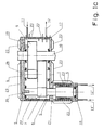
- FIG. 1 a A drive is schematically shown in FIG. 1 a, which comprises the motor 1 and the transmission 2 consists.
- the motor 1 is in a motor housing 3 and the transmission 2 in one Gear housing 4 housed.
- To assemble the motor 1 is usually on the Gearbox 2 facing away from the motor housing 3 (i.e. non-drive side) a bearing plate 18 arranged on the motor housing 3.
- the gear housing 4 can e.g. at the Motor 1 facing away from the transmission housing 4 for mounting and dismounting the Gear 2 have a gear cover 19.
- Motor 1 can be a electrical machine or an internal combustion engine. In the following Exemplary embodiments are only referred to electrical machines.
- the rotating one Motor shaft 6 protrudes from the motor housing 3 into the gear housing 4.
- gearbox 4 At the in Gearbox 4 arranged motor shaft 6 is a small wheel 7 rotatably with the motor shaft 6 connected, which drives the large wheel 9 via an intermediate shaft 8, which is rotatably connected to the drive shaft 10.
- the drive shaft 10 is with the part to be driven, e.g. a wheel of a vehicle (not shown).
- cooling channels 5 are provided, which together to form a cooling circuit are connected.
- One end of the cooling circuit is with a feed line 11 and the other end of the cooling circuit is connected to a return line 12 via which the cooling medium or is discharged.
- the cross section of the cooling channels 5 is preferably round or oval but theoretically have any shape.
- Cooling liquid especially a water-glycol mixture used. But it is also the one Use of other cooling liquids or a gaseous cooling medium possible.
- the Cooling of the transmission 2 can be combined with any cooling of the engine 1. in the Gearbox cover 19 can be arranged additional cooling channels. Furthermore is in the gear cover 19 a line 26 for introducing the transmission oil from the transmission space via a nozzle 35 arranged in the hollow motor shaft 6 for cooling them.
- a labyrinth seal 21 Seals gearbox from the engine compartment.
- Ribs 22, 23 or can also be used The same on the motor housing 3, gear housing 4, bearing plate 18 or gear cover 19th be provided.
- Ribs 22 arranged on the inside serve mainly to improve cooling by enlarging the inner surface while ribs 23 arranged outside mainly used for reinforcement, which means that the components are usually used with less Wall thicknesses can be carried out and even weight can be saved.
- the cooling of the transmission 2 is included the cooling of the engine 1 combined.
- the cooling circuit is in the Gearbox 4 connected to the cooling circuit in the motor housing 3, so that a common cooling circuit for the entire drive results.
- a line 13 of the transmission cooling connected to the cooling circuit of the transmission arranged that when the motor 1 and the transmission 2 are assembled with the line 15, which is connected to the circuit of the engine cooling.
- Line 14 of the gearbox cooling together with line 16 of the engine cooling.
- connection will advantageously sealed, for example with the aid of O-rings or the like (not shown).
- the connection can also be designed as a plug connection.
- the resulting common cooling circuit for engine 1 and transmission 2 has a supply line 11 and a return line 12 on the gear housing 4, via which the cooling medium is introduced or removed.
- the motor housing 3 common supply line 11 'or the return line 12' may be arranged.
- a combination a supply line 11 on the gear housing 4 and a return line 12 'on the motor housing 3 possible.
- more than one supply line 11, 11 'and return line 12, 12' to Connection of the common cooling circuit can be provided to the outside.
- FIG. 1c shows a particularly advantageous embodiment of the drive according to the invention, in which the motor 1 and the transmission 2 are housed in a common housing 17 are.
- a common cooling circuit for the cooling of the engine 1 and transmission 2 can be integrated.
- the cooling channels 5 are in the common housing 17 arranged so that they form a closed cooling circuit, without the need for connecting lines. Due to the one-piece construction of the housing 17 there can be no leakage of the cooling medium at connection points. For assembly and disassembly of the engine 1 and transmission 2 are forced openings in the common housing 17 required, which by the bearing plate 18 and Gear cover 19 to be completed.
- the end shield 18 and the gear cover 19 can include parts of the cooling channels, supply lines 11 'return lines 12', which advantageously be produced in one operation with the same.
- ribs 22, 23 or the like can also here on the common housing 17, bearing plate 18 or gear cover 19 is provided and with the common housing 17 be made in one operation.
- At least one feed line 11 and one return line 12 each are also provided Supply and return lines of the cooling medium.
- the tubes 20 can cover the entire cooling circuit or only form parts of it, in the latter case the subsequent connection of the Parts of the cooling circuit mean additional work and maintenance and the leakage losses of the cooling medium are increased as a result.
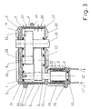
- Fig. 3 shows an embodiment of a drive according to the invention with a common housing 17 for the engine 1 and the transmission 2 in a sectional side view.
- the tubes 20 to form the common cooling circuit for the Motor 1 and gear 2 integrated.
- the labyrinth seal 21 which the Seals gearbox from the engine compartment can be done in one operation with the Housing 17 are made.
- the transmission suspension 24 and the engine mount 25 can be molded with the housing 17, for example.
- the line for delivering the transmission oil into the rotor shaft in the housing 17 is also provided be and be produced with it in one operation.
- the shield 18 and in Gear cover 19 can provide structures such as ribs or the like, but also lines his. 3 shows a line 26 for introducing the transmission oil from the transmission space into the hollow motor shaft 6 for cooling it.
- the supply line 11 'and the return line 12' for the Cooling medium for cooling the outer part of the engine 1 and the transmission 2 are in the embodiment shown provided in the bearing plate 18.
- the feed line 11 'and Return line 12 ' is connected to a pump and the reservoir of the cooling medium.
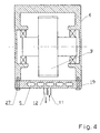
- Fig. 4 shows another embodiment variant of the transmission housing 4, the Gear cover 19 releasably connected to gear housing 4 via connecting screws 27 connected is.
- cooling channels 5 are integrated, which with at least a supply line 11 leading to the outside and at least one return line 12 are, so that a closed cooling circuit is formed.
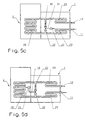
- 5a to 5d schematically show different variants of a combined gear motor cooling with integrated thermostat.
- a thermostat achieved that the gearbox only when an optimal operating temperature is reached is cooled and thus the optimal properties of the gear oil are exploited can.
- 5a the gearbox cooling circuit 28 with the engine cooling circuit 29 connected.
- the cooling medium is introduced into the cooling circuit via the feed line 11 and discharged via the return line 12.
- Parallel to the transmission cooling circuit 28 is one Bridging line 30 is arranged, which is closed by means of a valve 31 or the like can be.
- the valve 31 or the like can be similar to a cooler Motor vehicle via a bi-metal spring at a certain temperature be closed automatically.
- bypass line 30 at the sealed at the optimal temperature for the transmission oil, so that the cooling medium also passes through the transmission cooling circuit 28 and a further increase in the temperature in Counteracts transmission.
- By appropriate cross-section selection of the bypass line 30 is achieved that with the valve 31 open, the cooling medium essentially exclusively flows through the bypass line 30 and not through the transmission cooling circuit 28 without that a second valve in the transmission cooling circuit is required.
- FIG. 5b shows a variant of the thermostat-controlled transmission cooling, in which the valve 31 or the like. Is arranged in the transmission cooling circuit 28. When the optimum is reached Operating temperature of the transmission opens the valve 31 or the like, so that the cooling medium the transmission cooling circuit 28 can flow. Otherwise, the cooling medium is caused by the Bridging line 30 guided so that no cooling of the transmission takes place.
- the valve 32 can also be designed as an electromechanical valve be and be connected to a temperature sensor 33 via an electrical line 34.
- the temperature sensor 33 is preferably located within the transmission 2 Measurement of its operating temperature arranged.
- the invention is particularly aimed at traction drives of rail vehicles, where high performance and high heat losses occur.
- the electrical Machines can be used as an asynchronous machine, synchronous machine, or DC machine Transversal flow machine are present and designed as an inner rotor or outer rotor.
- An application with other drives, e.g. Internal combustion engines is also possible.
Landscapes
- Engineering & Computer Science (AREA)
- General Engineering & Computer Science (AREA)
- Mechanical Engineering (AREA)
- Power Engineering (AREA)
- General Details Of Gearings (AREA)
- Connection Of Motors, Electrical Generators, Mechanical Devices, And The Like (AREA)
- Motor Or Generator Frames (AREA)
Abstract
Description
- Fig. 1a bis 1c
- das Schema verschiedener Konstruktionen gekühlter Antriebe,
- Fig. 2
- eine Ausführungsvariante eines Getriebegehäuses mit Kühlung,
- Fig. 3
- eine Ausführungsvariante eines einstückigen Antriebs mit integrierter Kühlung.
- Fig. 4
- eine andere Ausführungsvariante des Getriebegehäuses, und
- Fig. 5a bis 5d
- schematisch verschiedene Varianten einer kombinierten Getriebe/Motorkühlung mit integriertem Thermostat.
Claims (10)
- Antrieb mit einem in einem Motorgehäuse (3) angeordneten Motor (1) und einem daran angeschlossenen, in einem Getriebegehäuse (4) angeordneten Getriebe (2), allenfalls mit einem mit dem Getriebegehäuse (4) lösbar verbundenen Getriebedeckel (19), wobei zumindest in einem Teil des Getriebegehäuses (4) und bzw. oder im Getriebedeckel (19) Kühlkanäle (5) zur Führung eines vorzugsweise flüssigen Kühlmittels angeordnet sind, dadurch gekennzeichnet, daß die Kühlkanäle (5) im Getriebegehäuse (4) und bzw. oder Getriebedeckel (19) mit Kühlkanälen im Motorgehäuse (3) zur Kühlung des Motors (1) verbunden sind.
- Antrieb nach Anspruch 1, dadurch gekennzeichnet, daß die Kühlkanäle (5) im Getriebegehäuse (4) und bzw. oder Getriebedeckel (19) integriert sind.
- Antrieb nach Anspruch 1 oder 2, dadurch gekennzeichnet, daß eine Überbrückungsleitung (30) parallel zu dem durch die Kühlkanäle (5) des Getriebegehäuses (4) und bzw. oder Getriebedeckels (19) gebildeten Getriebekühlkreislauf (28) vorgesehen ist, wobei in dieser Überbrückungsleitung (30) oder in zumindest einem der Kühlkanäle (5) des Getriebes ein Ventil (31, 32) od. dgl. zur Unterbrechung des Durchflusses des vorzugsweise flüssigen Kühlmittels angeordnet ist.
- Antrieb nach Anspruch 3, dadurch gekennzeichnet, daß das Ventil (31, 32) als elektronisches Ventil ausgebildet und mit einem vorzugsweise im Getriebegehäuse (4) angeordneten Temperatursensor (33) verbunden ist.
- Antrieb nach einem der Ansprüche 1 bis 4, dadurch gekennzeichnet, daß das Getriebegehäuse (3) an der, dem Motor (1) zugewandten Seite Leitungen (13, 14) aufweist, welche mit den Kühlkanälen (5) im Getriebegehäuse (4) verbunden sind, sodaß dicsc mit allfälligen Kiihlkanälen im Motorgehäuse (3) verbindbar sind.
- Antrieb nach einem der Ansprüche 1 bis 5. dadurch gekennzeichnet, daß das Motorgehäuse (3) und das Getriebegehäuse (4) einstückig als gemeinsames Gehäuse (17) ausgebildet sind, wobei in dem gemeinsamen Gehäuse (17) die Kühlkanäle (5) und allenfalls eine Überbrückungsleitung (30) angeordnet sind.
- Antrieb nach Anspruch 6, dadurch gekennzeichnet daß im gemeinsamen Gehäuse (17) des Motors (1) und des Getriebes (2) eine berührungslose Dichtung, z.B. eine Labyrinthdichtung (21) zur Abdichtung des Getrieberaumes gegenüber dem Motorraum vorgesehen ist.
- Antrieb nach Anspruch 6 oder 7, dadurch gekennzeichnet, daß auf dem gemeinsamen Gehäuse (17), allenfalls auf dem Getriebedeckel (19) und allenfalls auf einem mit dem Motorgehäuse (3) lösbar verbundenen Lagerschild (18) innenseitig und/oder außenseitig Rippen (22, 23) od. dgl. zur Versteifung und bzw. oder Verbesserung der Kühlwirkung angeordnet sind.
- Antrieb nach einem der Ansprüche 1 bis 8, dadurch gekennzeichnet, daß die Kühlkanäle (5) im Getriebegehäuse (4), Motorgehäuse (3) oder gemeinsamen Gehäuse (17), allfällige Überbrückungsleitungen (30), Leitungen (13, 14, 15, 16), Zuleitungen (11, 11') und Rückleitungen (12, 12') sowie allfällige Rippen (22, 23) od. dgl. im Getriebegehäuse (4), Motorgehäuse (3) oder gemeinsamen Gehäuse (17) mit diesem in einem Arbeitsvorgang durch Gießen oder Sintem hergestellt sind.
- Antrieb nach Anspruch 9, dadurch gekennzeichnet, daß die Kühlkanäle (5), allfällige Überbrückungsleitungen (30), Leitungen (13, 14, 15, 16), Zuleitungen (11, 11') und Rückleitungen (12, 12') durch Rohre (20) gebildet sind, welche aus einem Material mit höherem Schmelzpunkt als das Material des Getriebegehäuses (4), Motorgehäuses (3) oder gemeinsamen Gehäuses (17) bestehen.
Priority Applications (1)
| Application Number | Priority Date | Filing Date | Title |
|---|---|---|---|
| DE29924452U DE29924452U1 (de) | 1998-10-02 | 1999-09-28 | Antrieb |
Applications Claiming Priority (2)
| Application Number | Priority Date | Filing Date | Title |
|---|---|---|---|
| AT0165298A AT503361B1 (de) | 1998-10-02 | 1998-10-02 | Antrieb |
| AT165298 | 1998-10-02 |
Publications (2)
| Publication Number | Publication Date |
|---|---|
| EP0990820A2 true EP0990820A2 (de) | 2000-04-05 |
| EP0990820A3 EP0990820A3 (de) | 2002-07-24 |
Family
ID=3518053
Family Applications (1)
| Application Number | Title | Priority Date | Filing Date |
|---|---|---|---|
| EP99890309A Withdrawn EP0990820A3 (de) | 1998-10-02 | 1999-09-28 | Motorgetriebeeinheit mit gemeinsamer Kühlung |
Country Status (3)
| Country | Link |
|---|---|
| EP (1) | EP0990820A3 (de) |
| AT (1) | AT503361B1 (de) |
| PT (1) | PT9917U (de) |
Cited By (36)
| Publication number | Priority date | Publication date | Assignee | Title |
|---|---|---|---|---|
| WO2003006850A1 (de) * | 2001-07-12 | 2003-01-23 | Zf Friedrichshafen Ag | Anschluss einer getriebekühlung an den kühlkreislauf eines motors |
| GB2387206A (en) * | 2002-04-04 | 2003-10-08 | Ford Global Tech Inc | Gearbox cooling system |
| DE102004022863A1 (de) * | 2004-05-06 | 2005-12-01 | Sew-Eurodrive Gmbh & Co. Kg | Getriebe und Baukasten von Getrieben |
| DE10058111B4 (de) * | 2000-11-23 | 2010-08-05 | Zf Friedrichshafen Ag | Automatgetriebe |
| WO2010108696A1 (de) * | 2009-03-27 | 2010-09-30 | Sms Siemag Ag | Stranggussgetriebe mit hitzeabschirmung |
| EP2261534A1 (de) * | 2009-06-10 | 2010-12-15 | Siemens Aktiengesellschaft | Industriegetriebe |
| DE102009037548A1 (de) * | 2009-08-17 | 2011-04-07 | Sew-Eurodrive Gmbh & Co. Kg | Gehäuseteil für ein Getriebe und Verfahren zur Herstellung |
| WO2010123635A3 (en) * | 2009-04-20 | 2012-04-12 | General Electric Company | Integrated brushless starter/generator system |
| WO2012076141A3 (de) * | 2010-12-09 | 2012-10-18 | Sew-Eurodrive Gmbh & Co. Kg | Getriebemotor |
| DE102012012837A1 (de) | 2012-06-19 | 2013-12-19 | Getrag Getriebe- Und Zahnradfabrik Hermann Hagenmeyer Gmbh & Cie Kg | Schmierfluid-Temperierungsverfahren und- vorrichtung |
| DE102012012840A1 (de) | 2012-06-19 | 2013-12-19 | Getrag Getriebe- Und Zahnradfabrik Hermann Hagenmeyer Gmbh & Cie Kg | Gehäuseanordnung für eine Kupplungs-/Getriebeanordnung |
| WO2012079752A3 (de) * | 2010-12-14 | 2014-01-09 | Volkswagen Aktiengesellschaft | Verfahren zur herstellung eines elektromotorgehäuseteilrohlings und elektromotorgehäuseteil |
| DE102012022453A1 (de) | 2012-11-09 | 2014-05-15 | Getrag Getriebe- Und Zahnradfabrik Hermann Hagenmeyer Gmbh & Cie Kg | Elektrische Maschine und Kraftfahrzeug-Antriebsstrang |
| DE102012022451A1 (de) | 2012-11-09 | 2014-05-15 | Getrag Getriebe- Und Zahnradfabrik Hermann Hagenmeyer Gmbh & Cie Kg | Ringkanaleinrichtung, elektrische Maschine und Antriebsstrang |
| DE102012022452A1 (de) | 2012-11-09 | 2014-05-15 | Getrag Getriebe- Und Zahnradfabrik Hermann Hagenmeyer Gmbh & Cie Kg | Elektrische Maschine und Kraftfahrzeug-Antriebsstrang |
| DE102012111963A1 (de) * | 2012-12-07 | 2014-06-12 | Dr. Ing. H.C. F. Porsche Aktiengesellschaft | Achsgetriebeeinheit für ein Kraftfahrzeug |
| CN104734424A (zh) * | 2013-12-20 | 2015-06-24 | 西门子公司 | 具有集成润滑系统的驱动器布置 |
| CN108351017A (zh) * | 2015-11-24 | 2018-07-31 | 马自达汽车株式会社 | 结构体的壳体 |
| CN108583256A (zh) * | 2018-07-05 | 2018-09-28 | 重庆方巨科技集团有限公司 | 纯电动车动力驱动系统结构 |
| US10151380B2 (en) * | 2015-09-29 | 2018-12-11 | Mazda Motor Corporation | Transmission and manufacturing method of the same |
| US10302191B2 (en) * | 2015-07-21 | 2019-05-28 | Mazda Motor Corporation | Automatic transmission and method of manufacturing the same |
| CN110581619A (zh) * | 2019-09-11 | 2019-12-17 | 烟台菱辰能源有限公司 | 一种电机端盖和齿轮室一体式结构及电机及空压机 |
| WO2021099034A1 (de) * | 2019-11-20 | 2021-05-27 | Robert Bosch Gmbh | Modularer elektrischer achsantrieb |
| EP3926215A1 (de) * | 2020-06-15 | 2021-12-22 | Robert Bosch GmbH | Vorrichtung zur verbesserung der kühlung eines getriebegehäuses |
| CN113883258A (zh) * | 2020-07-02 | 2022-01-04 | 瑞维安知识产权控股有限责任公司 | 具有内部冷却销的齿轮箱 |
| WO2022175070A1 (de) * | 2021-02-18 | 2022-08-25 | Bayerische Motoren Werke Aktiengesellschaft | Getriebekühlung |
| US11466768B2 (en) * | 2018-12-31 | 2022-10-11 | Abb Schweiz Ag | Methods and systems for cooling transmissions |
| CN115298050A (zh) * | 2020-04-02 | 2022-11-04 | 罗伯特·博世有限公司 | 用于驱动系统的壳体和用以制造用于驱动系统的壳体的方法 |
| DE102021207386A1 (de) | 2021-07-13 | 2023-01-19 | Zf Friedrichshafen Ag | Getriebeanordnung für ein Kraftfahrzeug |
| EP4152575A1 (de) * | 2021-09-17 | 2023-03-22 | Robert Bosch GmbH | Elektrischer antrieb |
| WO2023057148A1 (de) * | 2021-10-04 | 2023-04-13 | Bayerische Motoren Werke Aktiengesellschaft | Kühlungsanordnungen für eine elektromotorische antriebseinheit bzw. deren komponenten |
| US20230184322A1 (en) * | 2020-05-12 | 2023-06-15 | Nissan Motor Co., Ltd. | Drive device |
| JP2024003505A (ja) * | 2022-06-27 | 2024-01-15 | 株式会社アイシン | 車両用駆動装置 |
| WO2024061424A1 (de) * | 2022-09-19 | 2024-03-28 | Quantron Ag | Getriebeeinheit für ein fahrzeug, fahrzeug und verfahren zum erwärmen von getriebeöl |
| JP2024049534A (ja) * | 2022-09-29 | 2024-04-10 | 本田技研工業株式会社 | ドライブユニット及び回転電機 |
| US20240360899A1 (en) * | 2023-04-26 | 2024-10-31 | Volkswagen Aktiengesellschaft | Drive train |
Families Citing this family (1)
| Publication number | Priority date | Publication date | Assignee | Title |
|---|---|---|---|---|
| DE102016009019A1 (de) * | 2016-07-23 | 2018-01-25 | Man Truck & Bus Ag | Mechanikstrang eines Fahrzeugantriebs |
Citations (10)
| Publication number | Priority date | Publication date | Assignee | Title |
|---|---|---|---|---|
| DE3331131A1 (de) | 1983-08-30 | 1985-03-07 | Volkswagenwerk Ag, 3180 Wolfsburg | Kuehleinrichtung fuer antriebsachsen |
| DE3606963A1 (de) | 1985-03-15 | 1986-09-25 | Zahnradfabrik Friedrichshafen Ag, 7990 Friedrichshafen | Maschinengehaeusemantel als oelkuehler |
| US4872502A (en) | 1987-09-25 | 1989-10-10 | The Falk Company | Air cooling of enclosed gear drives |
| DE4125079A1 (de) | 1990-08-06 | 1992-02-13 | Calsonic Co | Oelkuehler fuer automatisches getriebe |
| US5099715A (en) | 1987-04-02 | 1992-03-31 | Walter Baiker | Vehicle gear box in particular for heavy and special vehicles |
| DE4212243A1 (de) | 1991-04-23 | 1992-10-29 | Volkswagen Ag | Getriebe |
| EP0785612A1 (de) | 1995-12-20 | 1997-07-23 | ABB Daimler Benz Transportation Austria GmbH | Einrichtung zur Förderung des Getriebeöls zur Kühlung elektrischer Maschinen |
| WO1997044882A1 (de) | 1996-05-20 | 1997-11-27 | Abb Daimler-Benz Transportation Austria Gmbh | Flüssigkeitskühlung für elektrische maschinen |
| AT403864B (de) | 1994-06-13 | 1998-06-25 | Abb Daimler Benz Transp | Kühlsystem für eine elektrische maschine |
| EP0853225A2 (de) | 1997-01-10 | 1998-07-15 | KTM-Kühler GmbH | Kühler für das Öl im Gehäuse eines Getriebes |
Family Cites Families (2)
| Publication number | Priority date | Publication date | Assignee | Title |
|---|---|---|---|---|
| DE2148819C3 (de) * | 1971-09-30 | 1982-02-25 | Gewerkschaft Eisenhütte Westfalia, 4670 Lünen | Kühlvorrichtung für eine Getriebeanordnung, insbesondere für den Antrieb von Gewinnungs- und Fördereinrichtungen für den Bergbau |
| ATE157822T1 (de) * | 1993-12-23 | 1997-09-15 | Abb Daimler Benz Transp | Kühlsystem für einen motor |
-
1998
- 1998-10-02 AT AT0165298A patent/AT503361B1/de not_active IP Right Cessation
-
1999
- 1999-09-28 EP EP99890309A patent/EP0990820A3/de not_active Withdrawn
-
2003
- 2003-10-23 PT PT9917U patent/PT9917U/pt not_active IP Right Cessation
Patent Citations (10)
| Publication number | Priority date | Publication date | Assignee | Title |
|---|---|---|---|---|
| DE3331131A1 (de) | 1983-08-30 | 1985-03-07 | Volkswagenwerk Ag, 3180 Wolfsburg | Kuehleinrichtung fuer antriebsachsen |
| DE3606963A1 (de) | 1985-03-15 | 1986-09-25 | Zahnradfabrik Friedrichshafen Ag, 7990 Friedrichshafen | Maschinengehaeusemantel als oelkuehler |
| US5099715A (en) | 1987-04-02 | 1992-03-31 | Walter Baiker | Vehicle gear box in particular for heavy and special vehicles |
| US4872502A (en) | 1987-09-25 | 1989-10-10 | The Falk Company | Air cooling of enclosed gear drives |
| DE4125079A1 (de) | 1990-08-06 | 1992-02-13 | Calsonic Co | Oelkuehler fuer automatisches getriebe |
| DE4212243A1 (de) | 1991-04-23 | 1992-10-29 | Volkswagen Ag | Getriebe |
| AT403864B (de) | 1994-06-13 | 1998-06-25 | Abb Daimler Benz Transp | Kühlsystem für eine elektrische maschine |
| EP0785612A1 (de) | 1995-12-20 | 1997-07-23 | ABB Daimler Benz Transportation Austria GmbH | Einrichtung zur Förderung des Getriebeöls zur Kühlung elektrischer Maschinen |
| WO1997044882A1 (de) | 1996-05-20 | 1997-11-27 | Abb Daimler-Benz Transportation Austria Gmbh | Flüssigkeitskühlung für elektrische maschinen |
| EP0853225A2 (de) | 1997-01-10 | 1998-07-15 | KTM-Kühler GmbH | Kühler für das Öl im Gehäuse eines Getriebes |
Cited By (67)
| Publication number | Priority date | Publication date | Assignee | Title |
|---|---|---|---|---|
| DE10058111B4 (de) * | 2000-11-23 | 2010-08-05 | Zf Friedrichshafen Ag | Automatgetriebe |
| US7162936B2 (en) | 2001-07-12 | 2007-01-16 | Zf Friedrichshafen Ag | Connection of a gearbox cooling to the cooling circuit of an engine |
| WO2003006850A1 (de) * | 2001-07-12 | 2003-01-23 | Zf Friedrichshafen Ag | Anschluss einer getriebekühlung an den kühlkreislauf eines motors |
| GB2387206A (en) * | 2002-04-04 | 2003-10-08 | Ford Global Tech Inc | Gearbox cooling system |
| GB2387206B (en) * | 2002-04-04 | 2005-08-10 | Ford Global Tech Inc | A transmission housing with cooling passageways |
| DE102004022863A1 (de) * | 2004-05-06 | 2005-12-01 | Sew-Eurodrive Gmbh & Co. Kg | Getriebe und Baukasten von Getrieben |
| DE102004022863B4 (de) * | 2004-05-06 | 2010-08-05 | Sew-Eurodrive Gmbh & Co. Kg | Getriebe |
| CN102365477A (zh) * | 2009-03-27 | 2012-02-29 | Sms西马格股份公司 | 带有热隔离的连续铸造传动装置 |
| WO2010108696A1 (de) * | 2009-03-27 | 2010-09-30 | Sms Siemag Ag | Stranggussgetriebe mit hitzeabschirmung |
| CN102577033A (zh) * | 2009-04-20 | 2012-07-11 | 通用电气公司 | 集成无刷式起动器/发电器系统 |
| WO2010123635A3 (en) * | 2009-04-20 | 2012-04-12 | General Electric Company | Integrated brushless starter/generator system |
| CN102577033B (zh) * | 2009-04-20 | 2015-02-11 | 通用电气公司 | 集成无刷式起动器/发电器系统 |
| US8450888B2 (en) | 2009-04-20 | 2013-05-28 | General Electric Company | Integrated brushless starter/generator system |
| EP2261534A1 (de) * | 2009-06-10 | 2010-12-15 | Siemens Aktiengesellschaft | Industriegetriebe |
| DE102009037548A1 (de) * | 2009-08-17 | 2011-04-07 | Sew-Eurodrive Gmbh & Co. Kg | Gehäuseteil für ein Getriebe und Verfahren zur Herstellung |
| WO2012076141A3 (de) * | 2010-12-09 | 2012-10-18 | Sew-Eurodrive Gmbh & Co. Kg | Getriebemotor |
| CN103262397A (zh) * | 2010-12-09 | 2013-08-21 | 索尤若驱动有限及两合公司 | 减速电机 |
| CN103262397B (zh) * | 2010-12-09 | 2016-05-04 | 索尤若驱动有限及两合公司 | 减速电机 |
| WO2012079752A3 (de) * | 2010-12-14 | 2014-01-09 | Volkswagen Aktiengesellschaft | Verfahren zur herstellung eines elektromotorgehäuseteilrohlings und elektromotorgehäuseteil |
| CN103732335A (zh) * | 2010-12-14 | 2014-04-16 | 大众汽车有限公司 | 用于制造电动机壳体件毛坯的方法和电动机壳体件 |
| DE102010054496B4 (de) | 2010-12-14 | 2020-06-18 | Volkswagen Ag | Durch Gießen hergestelltes Elektromotorgehäuseteil für einen Elektromotor |
| CN103732335B (zh) * | 2010-12-14 | 2018-07-17 | 大众汽车有限公司 | 用于制造电动机壳体件毛坯的方法和电动机壳体件 |
| WO2013189754A1 (de) * | 2012-06-19 | 2013-12-27 | Getrag Getriebe- Und Zahnradfabrik Hermann Hagenmeyer Gmbh & Cie Kg | Schmierfluid-temperierungsverfahren und -vorrichtung |
| DE102012012840A1 (de) | 2012-06-19 | 2013-12-19 | Getrag Getriebe- Und Zahnradfabrik Hermann Hagenmeyer Gmbh & Cie Kg | Gehäuseanordnung für eine Kupplungs-/Getriebeanordnung |
| DE102012012837A1 (de) | 2012-06-19 | 2013-12-19 | Getrag Getriebe- Und Zahnradfabrik Hermann Hagenmeyer Gmbh & Cie Kg | Schmierfluid-Temperierungsverfahren und- vorrichtung |
| DE102012022452B4 (de) | 2012-11-09 | 2018-04-05 | Getrag Getriebe- Und Zahnradfabrik Hermann Hagenmeyer Gmbh & Cie Kg | Elektrische Maschine und Kraftfahrzeug-Antriebsstrang |
| DE102012022451B4 (de) * | 2012-11-09 | 2016-08-18 | Getrag Getriebe- Und Zahnradfabrik Hermann Hagenmeyer Gmbh & Cie Kg | Ringkanaleinrichtung, elektrische Maschine und Antriebsstrang |
| DE102012022453A1 (de) | 2012-11-09 | 2014-05-15 | Getrag Getriebe- Und Zahnradfabrik Hermann Hagenmeyer Gmbh & Cie Kg | Elektrische Maschine und Kraftfahrzeug-Antriebsstrang |
| DE102012022451A1 (de) | 2012-11-09 | 2014-05-15 | Getrag Getriebe- Und Zahnradfabrik Hermann Hagenmeyer Gmbh & Cie Kg | Ringkanaleinrichtung, elektrische Maschine und Antriebsstrang |
| DE102012022452A1 (de) | 2012-11-09 | 2014-05-15 | Getrag Getriebe- Und Zahnradfabrik Hermann Hagenmeyer Gmbh & Cie Kg | Elektrische Maschine und Kraftfahrzeug-Antriebsstrang |
| DE102012111963B4 (de) * | 2012-12-07 | 2021-07-08 | Dr. Ing. H.C. F. Porsche Aktiengesellschaft | Achsgetriebeeinheit für ein Kraftfahrzeug |
| DE102012111963A1 (de) * | 2012-12-07 | 2014-06-12 | Dr. Ing. H.C. F. Porsche Aktiengesellschaft | Achsgetriebeeinheit für ein Kraftfahrzeug |
| CN104734424A (zh) * | 2013-12-20 | 2015-06-24 | 西门子公司 | 具有集成润滑系统的驱动器布置 |
| CN104734424B (zh) * | 2013-12-20 | 2017-10-31 | 西门子公司 | 具有集成润滑系统的驱动器布置 |
| DE102013226804B4 (de) * | 2013-12-20 | 2015-07-09 | Siemens Aktiengesellschaft | Antriebsanordnung mit integrierter Schmierung |
| DE102013226804A1 (de) * | 2013-12-20 | 2015-06-25 | Siemens Aktiengesellschaft | Antriebsanordnung mit integrierter Schmierung |
| US10302191B2 (en) * | 2015-07-21 | 2019-05-28 | Mazda Motor Corporation | Automatic transmission and method of manufacturing the same |
| DE102016008641B4 (de) | 2015-07-21 | 2020-08-06 | Mazda Motor Corporation | Automatikgetriebe und Herstellungsverfahren hierfür |
| US10151380B2 (en) * | 2015-09-29 | 2018-12-11 | Mazda Motor Corporation | Transmission and manufacturing method of the same |
| US20180259056A1 (en) * | 2015-11-24 | 2018-09-13 | Mazda Motor Corporation | Case of structure |
| CN108351017A (zh) * | 2015-11-24 | 2018-07-31 | 马自达汽车株式会社 | 结构体的壳体 |
| US10465789B2 (en) * | 2015-11-24 | 2019-11-05 | Mazda Motor Corporation | Case of structure |
| DE112016005375B4 (de) | 2015-11-24 | 2021-08-12 | Mazda Motor Corporation | Eine Struktur aufweisendes Gehäuse |
| CN108583256A (zh) * | 2018-07-05 | 2018-09-28 | 重庆方巨科技集团有限公司 | 纯电动车动力驱动系统结构 |
| US11466768B2 (en) * | 2018-12-31 | 2022-10-11 | Abb Schweiz Ag | Methods and systems for cooling transmissions |
| CN110581619A (zh) * | 2019-09-11 | 2019-12-17 | 烟台菱辰能源有限公司 | 一种电机端盖和齿轮室一体式结构及电机及空压机 |
| CN110581619B (zh) * | 2019-09-11 | 2022-03-25 | 烟台东德氢能技术有限公司 | 一种电机端盖和齿轮室一体式结构及电机及空压机 |
| WO2021099034A1 (de) * | 2019-11-20 | 2021-05-27 | Robert Bosch Gmbh | Modularer elektrischer achsantrieb |
| CN115298050B (zh) * | 2020-04-02 | 2026-03-06 | 罗伯特·博世有限公司 | 用于驱动系统的壳体和用以制造用于驱动系统的壳体的方法 |
| CN115298050A (zh) * | 2020-04-02 | 2022-11-04 | 罗伯特·博世有限公司 | 用于驱动系统的壳体和用以制造用于驱动系统的壳体的方法 |
| US11781640B2 (en) * | 2020-05-12 | 2023-10-10 | Nissan Motor Co., Ltd. | Drive device |
| US20230184322A1 (en) * | 2020-05-12 | 2023-06-15 | Nissan Motor Co., Ltd. | Drive device |
| EP3926215A1 (de) * | 2020-06-15 | 2021-12-22 | Robert Bosch GmbH | Vorrichtung zur verbesserung der kühlung eines getriebegehäuses |
| CN113883258B (zh) * | 2020-07-02 | 2025-03-11 | 瑞维安知识产权控股有限责任公司 | 具有内部冷却销的齿轮箱 |
| US11261956B2 (en) * | 2020-07-02 | 2022-03-01 | Rivian Ip Holdings, Llc | Gearbox having internal cooling pins |
| US20220003308A1 (en) * | 2020-07-02 | 2022-01-06 | Rivian Ip Holdings, Llc | Gearbox having internal cooling pins |
| US11867279B2 (en) | 2020-07-02 | 2024-01-09 | Rivian Ip Holdings, Llc | Gearbox having internal cooling pins |
| CN113883258A (zh) * | 2020-07-02 | 2022-01-04 | 瑞维安知识产权控股有限责任公司 | 具有内部冷却销的齿轮箱 |
| WO2022175070A1 (de) * | 2021-02-18 | 2022-08-25 | Bayerische Motoren Werke Aktiengesellschaft | Getriebekühlung |
| DE102021207386A1 (de) | 2021-07-13 | 2023-01-19 | Zf Friedrichshafen Ag | Getriebeanordnung für ein Kraftfahrzeug |
| EP4152575A1 (de) * | 2021-09-17 | 2023-03-22 | Robert Bosch GmbH | Elektrischer antrieb |
| WO2023057148A1 (de) * | 2021-10-04 | 2023-04-13 | Bayerische Motoren Werke Aktiengesellschaft | Kühlungsanordnungen für eine elektromotorische antriebseinheit bzw. deren komponenten |
| JP2024003505A (ja) * | 2022-06-27 | 2024-01-15 | 株式会社アイシン | 車両用駆動装置 |
| WO2024061424A1 (de) * | 2022-09-19 | 2024-03-28 | Quantron Ag | Getriebeeinheit für ein fahrzeug, fahrzeug und verfahren zum erwärmen von getriebeöl |
| JP2024049534A (ja) * | 2022-09-29 | 2024-04-10 | 本田技研工業株式会社 | ドライブユニット及び回転電機 |
| US20240360899A1 (en) * | 2023-04-26 | 2024-10-31 | Volkswagen Aktiengesellschaft | Drive train |
| US12345321B2 (en) * | 2023-04-26 | 2025-07-01 | Volkswagen Aktiengesellschaft | Drive train |
Also Published As
| Publication number | Publication date |
|---|---|
| AT503361A1 (de) | 2007-09-15 |
| AT503361B1 (de) | 2011-10-15 |
| PT9917T (pt) | 2004-04-30 |
| PT9917U (pt) | 2004-12-31 |
| EP0990820A3 (de) | 2002-07-24 |
Similar Documents
| Publication | Publication Date | Title |
|---|---|---|
| AT503361B1 (de) | Antrieb | |
| EP3878080B1 (de) | Elektrische maschine mit einer fluid-kühleinrichtung | |
| DE102019109313B4 (de) | Elektrischer Antrieb mit Wärmetauscherabschnitt | |
| DE3738592C1 (en) | Electric motor for driving a liquid pump, and a method for its production | |
| DE102012202460A1 (de) | Elektromotorische Getriebevorrichtung mit einstückigem Gehäuse | |
| DE69905184T2 (de) | Verbesserung in oder an pumpenvorrichtung für brennkraftmaschine | |
| DE19509417A1 (de) | Antriebseinheit | |
| EP1317790B1 (de) | Flüssigkeitsgekühlter elektromotor | |
| EP0858692B1 (de) | Flüssigkeitskühlung für elektrische maschinen | |
| DE102021207527A1 (de) | Getriebe für ein integrales Differential, integrales Differential sowie Antriebsstrang | |
| AT403864B (de) | Kühlsystem für eine elektrische maschine | |
| EP1963674B1 (de) | Wassergekühlter kolbenverdichter | |
| DE102010064061A1 (de) | Turboverdichter und Verfahren zur Verdichtung von Gas | |
| WO2006063788A2 (de) | Kompakter schraubenkompressor zum mobilen einsatz in einem fahrzeug | |
| WO2020169189A1 (de) | Mehrteiliges segmentiertes e-maschinengehäuse | |
| EP0722867B1 (de) | Antriebseinheit mit einer Brennkraftmaschine und einem hydrodynamischen Retarder | |
| DE29924452U1 (de) | Antrieb | |
| EP0711692A1 (de) | Antriebseinheit mit einer Brennkraftmaschine und einem hydrodynamischen Retarder | |
| DE10307566A1 (de) | Elektrohydraulisches Doppelpumpen-Doppelmotor-Aggregat für eine selbstfahrende Arbeitsmaschine, insbesondere Flurförderzeug | |
| DE102014223642A1 (de) | Antriebseinrichtung | |
| DE19828406A1 (de) | Elektromotor | |
| DE102019117155A1 (de) | Elektrischer Antrieb für ein Fahrzeug sowie Fahrzeug mit dem elektrischen Antrieb | |
| EP0711691A1 (de) | Antriebseinheit mit einer Brennkraftmaschine und einem hydrodynamischen Retarder | |
| EP0716966A2 (de) | Antriebseinheit | |
| DE10339433A1 (de) | Selbsttragendes Antriebsmodul |
Legal Events
| Date | Code | Title | Description |
|---|---|---|---|
| PUAI | Public reference made under article 153(3) epc to a published international application that has entered the european phase |
Free format text: ORIGINAL CODE: 0009012 |
|
| AK | Designated contracting states |
Kind code of ref document: A2 Designated state(s): AT BE CH CY DE DK ES FI FR GB GR IE IT LI LU MC NL PT SE |
|
| AX | Request for extension of the european patent |
Free format text: AL;LT;LV;MK;RO;SI |
|
| RAP1 | Party data changed (applicant data changed or rights of an application transferred) |
Owner name: BOMBARDIER TRANSPORTATION GMBH |
|
| RAP1 | Party data changed (applicant data changed or rights of an application transferred) |
Owner name: DAIMLERCHRYSLER AG |
|
| PUAL | Search report despatched |
Free format text: ORIGINAL CODE: 0009013 |
|
| AK | Designated contracting states |
Kind code of ref document: A3 Designated state(s): AT BE CH CY DE DK ES FI FR GB GR IE IT LI LU MC NL PT SE |
|
| AX | Request for extension of the european patent |
Free format text: AL;LT;LV;MK;RO;SI |
|
| STAA | Information on the status of an ep patent application or granted ep patent |
Free format text: STATUS: THE APPLICATION HAS BEEN WITHDRAWN |
|
| 18W | Application withdrawn |
Effective date: 20021217 |
|
| 110E | Request filed for conversion into a national patent application [according to art. 135 epc] |
Effective date: 20030218 |
|
| APAF | Appeal reference modified |
Free format text: ORIGINAL CODE: EPIDOSCREFNE |
|
| APAF | Appeal reference modified |
Free format text: ORIGINAL CODE: EPIDOSCREFNE |