EP0992649A1 - Zerlegbarer Schrank dessen Inhalt gegen Hitze geschützt ist - Google Patents
Zerlegbarer Schrank dessen Inhalt gegen Hitze geschützt ist Download PDFInfo
- Publication number
- EP0992649A1 EP0992649A1 EP98390013A EP98390013A EP0992649A1 EP 0992649 A1 EP0992649 A1 EP 0992649A1 EP 98390013 A EP98390013 A EP 98390013A EP 98390013 A EP98390013 A EP 98390013A EP 0992649 A1 EP0992649 A1 EP 0992649A1
- Authority
- EP
- European Patent Office
- Prior art keywords
- panel
- wall
- internal
- wing
- walls
- Prior art date
- Legal status (The legal status is an assumption and is not a legal conclusion. Google has not performed a legal analysis and makes no representation as to the accuracy of the status listed.)
- Withdrawn
Links
- 239000000919 ceramic Substances 0.000 claims abstract description 18
- 210000002268 wool Anatomy 0.000 claims abstract description 18
- 239000002184 metal Substances 0.000 claims abstract description 15
- 229910052751 metal Inorganic materials 0.000 claims abstract description 15
- 239000004568 cement Substances 0.000 claims abstract description 10
- 239000012774 insulation material Substances 0.000 claims abstract description 5
- 238000009413 insulation Methods 0.000 claims description 48
- 239000000463 material Substances 0.000 claims description 14
- 239000011324 bead Substances 0.000 claims description 8
- 230000001681 protective effect Effects 0.000 claims description 5
- 229910000746 Structural steel Inorganic materials 0.000 claims description 4
- 230000000694 effects Effects 0.000 claims description 3
- 230000007246 mechanism Effects 0.000 claims description 3
- 230000007423 decrease Effects 0.000 claims description 2
- 230000004907 flux Effects 0.000 claims description 2
- 239000011810 insulating material Substances 0.000 claims description 2
- 230000010339 dilation Effects 0.000 claims 1
- 230000000284 resting effect Effects 0.000 claims 1
- 230000003014 reinforcing effect Effects 0.000 abstract 1
- 238000003466 welding Methods 0.000 description 4
- 125000006850 spacer group Chemical group 0.000 description 3
- 229910000831 Steel Inorganic materials 0.000 description 2
- 230000004888 barrier function Effects 0.000 description 2
- 230000006866 deterioration Effects 0.000 description 2
- 239000010959 steel Substances 0.000 description 2
- 230000004075 alteration Effects 0.000 description 1
- 230000005540 biological transmission Effects 0.000 description 1
- 239000000945 filler Substances 0.000 description 1
- 239000003517 fume Substances 0.000 description 1
- 239000012212 insulator Substances 0.000 description 1
- 238000004519 manufacturing process Methods 0.000 description 1
- 239000011819 refractory material Substances 0.000 description 1
- 238000010079 rubber tapping Methods 0.000 description 1
- 238000007789 sealing Methods 0.000 description 1
- 238000000926 separation method Methods 0.000 description 1
- 230000035939 shock Effects 0.000 description 1
- XLYOFNOQVPJJNP-UHFFFAOYSA-N water Substances O XLYOFNOQVPJJNP-UHFFFAOYSA-N 0.000 description 1
Images


Classifications
-
- E—FIXED CONSTRUCTIONS
- E05—LOCKS; KEYS; WINDOW OR DOOR FITTINGS; SAFES
- E05G—SAFES OR STRONG-ROOMS FOR VALUABLES; BANK PROTECTION DEVICES; SAFETY TRANSACTION PARTITIONS
- E05G1/00—Safes or strong-rooms for valuables
- E05G1/02—Details
- E05G1/024—Wall or panel structure
-
- E—FIXED CONSTRUCTIONS
- E05—LOCKS; KEYS; WINDOW OR DOOR FITTINGS; SAFES
- E05Y—INDEXING SCHEME ASSOCIATED WITH SUBCLASSES E05D AND E05F, RELATING TO CONSTRUCTION ELEMENTS, ELECTRIC CONTROL, POWER SUPPLY, POWER SIGNAL OR TRANSMISSION, USER INTERFACES, MOUNTING OR COUPLING, DETAILS, ACCESSORIES, AUXILIARY OPERATIONS NOT OTHERWISE PROVIDED FOR, APPLICATION THEREOF
- E05Y2900/00—Application of doors, windows, wings or fittings thereof
- E05Y2900/20—Application of doors, windows, wings or fittings thereof for furniture, e.g. cabinets
Definitions
- the present invention relates to a removable cabinet for protection against strong heat like those released during fires.
- the object of the present invention is to overcome the drawbacks mentioned above in offering a removable cabinet designed so that the storage volume is protected from heat and so that the temperature in the latter is lower than the ignition temperature of the paper for certain area and at the alteration temperature of the recordings on magnetic media for other areas.
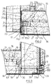
- the removable cabinet according to the invention comprising a horizontal bottom wall with legs, a vertical rear wall assembled to the back wall, two vertical side walls, assembled to the walls bottom and rear, a horizontal upper wall placed on the horizontal upper edges of the walls rear and side and assembled to the rear and side walls and a door has one or more leaves hinged mounted on hinges fixed to one of the side walls, coming in the closed position against front edges of the bottom, side and top walls, which edges define the opening quadrangular of the storage volume and all develop along the same vertical plane (P), essentially characterized in that each wall and door leaf is constituted by a first metal panel external to the storage volume, by a second metal panel internal to the storage volume and kept at a distance from the previous one by at least one layer of a material of filling with thermal insulation qualities, and that thermal insulation joints are arranged between the walls at their junction which decreases, for each wall, the importance of heat flow between the external panel and the internal panel on the one hand and the importance of the heat
- the cabinet has increased thermal insulation both in the direction of the thickness of the walls than from one wall to the other.
- two layers of material are provided. filling in between the panels, one of which is made of refractory cement and comes against the internal face of the first panel and completely covers said face and of which the other is made by ceramic wool, the second layer being placed between the first layer and the face of the second internal panel at the interval between the panels and completely covering the first layer and said internal face of the second panel.
- This provision which provides for the use of a layer of refractory cement in contact with the external panel, ie the one most exposed to heat, increases the mechanical resistance of the wall and in particular avoids its deformation under the effect of a high temperature.
- the front edge of each bottom wall, side and top is constituted by a front wing of the internal panel to the storage volume by a front wing of the panel external to the storage volume, the two wings being spaced from one another, the front wing of the inner panel, facing the outer panel, being folded along two fold lines successively parallel in one direction and then in the other to form a right angle offset while the wing of the outer panel, facing the inner panel, along a parallel fold line at the fold lines of the front wing, is folded towards the inside of the wall, parallel to the panels internal and external, to come opposite the recess and form with it, a groove longitudinal running along the entire length of the front edge, said groove receiving an insulation joint thermal, of quadrangular cross section against which the internal face of the leaf of the door in closed position.
- the internal face of the door leaf takes support against the thermal insulation joints by means of longitudinal bosses which it present, said bosses in the closed position of the door leaf coming into the grooves of the joints.
- thermal insulation joints are arranged, under strip form, between the door leaf and the front edges of the bottom, side, and top walls proximity to the grooves, overlapping the portions arranged along the plane (P) of the front wing of each internal and external panels of each said wall.
- the front wing of each external panel behind of the offset formed by the front wing of the corresponding external panel, is folded at right angles to rear of said recess and spacing of the latter so as to form in combination with this last a groove forming a vacuum.
- the internal face of the door leaf is provided with a quadrangular allowance with a vertical face internal to the storage volume whose width and height are slightly less than the height and width of the opening quadrangular storage volume, said extra thickness in the closed position of the leaf of the door coming to be arranged in the storage volume, and by its internal face coming to bear against thermal insulation joints arranged in the same vertical plane in grooves formed by profiles in combination with the internal faces of the storage volume of the internal panels of the bottom walls, lateral and upper.
- the internal face of the door leaf around the allowance and said allowance, in closing position of the door leaf preferably remain a few millimeters away from the bottom, side and top walls of the cabinet which further contributes to reducing the importance of heat flow between the door leaf and the walls, in the closed position of said leaf.
- the bottom, rear, side and upper walls are fixed to each other by through screws, the heads of which protrude from the panels external and are covered by protective cages attached to the external panels, in which around the screw heads, a thermal insulation material is arranged.
- This arrangement avoids any thermal shock between the screw heads and the threaded rods leading to deterioration of the screw by tearing off the head and avoids the use of refractory steel screws which is likely to reduce the cost of manufacturing the cabinet.
- the screws for fixing two walls to one another are spaced apart from each other in a straight line and the heads of these screws are covered by a single protective cage made up of a U-shaped section coming from its lateral wings on either side of the screw heads and from the edges of the supporting lateral wings against the outer panel of the corresponding wall.
- the removable cabinet according to the invention the internal volume of which is protected high temperatures known as those of a fire, for example, comprises a bottom wall 1, horizontal, possibly with legs for stable support on the ground, a rear wall vertical 2, assembled, removably to the bottom wall, two vertical side walls 3, removably assembled to the bottom wall 1 and to the rear wall 2, an upper wall horizontal 4, placed on the upper horizontal edges of the rear and side walls and assembled demountable way to said rear 2 and side walls 3 and a door 5 comprising at least one leaf mounted articulated on hinges 6 fixed to one of the side walls 3.
- the bottom wall 1 is mounted in a metal base 7 formed by a flat panel 8, bearing on the ground, and a crown 9 forming a belt, erected on the flat panel 7 to determine with this last a volume open upwards in which is disposed on said bottom panel, the wall 1.
- This thick wall 1 thermally insulating, collects the weight of the charges present in the volume of storage of the cabinet and transmits them to the base 7, said wall 1 with the crown 9 of the determining base a substantially U-shaped gap into which the lower ends of the walls are introduced lateral 3 and rear 2 for attachment to the crown 9 of the base.
- the flat panel 8 of the base 7, in the volume it determines with the crown 9, is lined with a layer of thermal insulation 11 capable of supporting the loads.
- a layer of thermal insulation 11 capable of supporting the loads.
- thermal insulation rest the bottom wall 1 and the horizontal lower edges of the side walls 3 and rear 2.
- the bottom wall 1 is constituted by an upper panel 12 internal to the storage volume and forming the bottom of said volume and a bottom external panel 13 of the storage volume separated from the previous to determine an interval in which is arranged at least one layer of a material insulating.
- a layer of refractory cement 14 may be placed bearing on the lower panel and a layer of ceramic wool on the layer of refractory cement.
- the lower panel 13 of the wall 1 comprises two lateral wings 16, a front wing 17 and a rear wing 18, these wings 16, 17, 18 being directed towards the upper panel 12.
- At least the lateral wings 16 are fixed, for example by welding, metal rods 19 rigid, vertical, bracing, small section, to which the panel is fixed by welding upper 12, the latter comprising a front wing 20, two lateral wings 21 and possibly a wing rear, these different wings being all oriented towards the lower panel.
- the stems vertical bracing 19 are fixed by welding to the side wings 21 of the upper panel.
- the front wing 12 of the upper panel has a vertical portion 20a rooted in the panel a horizontal portion 20b extending in the bottom wall 1 and separated from the previous one by a line of right angle fold, and third vertical portion 20c separated from the horizontal portion 20b by a line right angle bend, said vertical portion 20c extending towards the bottom panel.
- the front wing 17 of the lower panel 13 has a vertical portion 17a to which is rooted along a fold line a horizontal portion 17b.
- the portions 20b and 20c of the wing 20 of the upper panel and the portion 17a of the wing 17 of the lower panel determine a horizontal groove 23 of polygonal cross section, intended to receive a thermal insulator 24 in the form of a cord against which the internal face of the door bears closing position of the leaf (s).
- ceramic wool may be used for making the insulation bead 24.
- the internal face of the door leaf, facing the groove 23, has a slender bead horizontal 25 intended to penetrate into the groove 23 and come to bear against the seal 24 and between the portions 20a, 17a and the internal face of the door leaf can be arranged an insulating element 26 thermal in sheet form, preferably made of ceramic wool. More generally this sheet may also cover the front edges of the side walls 3 and top 4.
- the portion 17b of the front wing of the lower panel is extended vertically upwards by rear and in separation of the portion 20c of the front wing of the upper panel by a portion 17c determining with the portion 17b a longitudinal groove forming a vacuum.
- a Z-profile, 27 forming three perpendicular wings two by two, two of which determine with the internal face the volume of storage of the upper panel, a groove 27a, of polygonal cross section, in which is disposed a thermal insulation cord 28 against which the internal face of the storage volume is supported, with an extra thickness 5a presented by the door 5.
- the rear 18 and side 16 wings of the lower panel 13, in the upper part, may be each folded so as to form a recess la, the recesses la of the side walls 3 and rear 2 being arranged in the same horizontal plane and receiving in support one or more cord (s) of thermal insulation 29 coming against the internal face of the storage volume, respectively of the wall rear 2 and side walls 3.
- the rear wings 18 and side 16 and the internal faces at storage volume of the side walls 3 and rear 2 under the insulation cord (s) 29, may be interposed thermal insulation seals 30 in the form of a strip.
- the base 7 of the bottom wall 1 bears externally on its crown 9 and on the area of this last facing the rear 2 and side 3 walls, a horizontal, elongated boss 31, provided according to the same horizontal plane, of a plurality of through holes 32.
- the wall of the crown also has a through hole.
- fixing screws 40 of the rear 2 and side 3 walls in the base these screws fixing 40 being screwed into threads made in said walls.
- the vertical rear wall 2 consists of an external panel 33 with storage space or first panel, from an internal panel 34 to said volume or second panel, separated from the previous one and from a filling material, thermal insulation, placed in the gap between the two panels according to minus a vertical layer.
- two layers are provided, namely, a layer of refractory cement 35 coming against the external panel and a layer of ceramic wool 36 coming against the refractory layer and counting the internal panel 34.
- the rear wall 2 in the space between the two panels 33, 34 is provided with an element elongated upper stiffening 37, horizontal fixed against the inner face of the outer panel and a elongated lower stiffening element 38, horizontal fixed against the internal face of the external panel 33.
- These stiffening elements carry several rigid, horizontal, bracing figs 39 extending in the direction of the thickness of the wall. At the end, the figs receive in fixing, the panel internal 34.
- the rigid figs preferably made of metal, are of small section in order to minimize the importance of the heat flow between the external and internal panels. These rods are mainly used for maintain the internal panel in relation to the external panel.
- each stiffening element is constituted by a angle iron fixed by the flat of one of its wings to the face of the internal panel 33 at the interval between the panels, the rigid spacer rods 39 being fixed to the bank of the other wing.
- a longitudinal boss 33a provided with a plurality of threads axially aligned with through holes made in the panel. In tapping, are engaged in screwing the fixing screws 40.
- the outer panel 33 of the rear wall 2 has respectively, along the two edges vertical of said wall, two lateral wings 41. According to the two vertical lateral banks respectively from the wall 2, the internal panel 34 also includes two lateral wings 42.
- Each wing 41 along its entire height, is folded at right angles successively along two lines folding in one direction and in the other to form a recess facing the internal panel.
- One of the aims of this step is to form a longitudinal stiffening rib.
- Each side wing 42 along its entire height, is folded at right angles parallel to the panel towards the inside of the wall 2 and comes opposite the recess of the corresponding wing 41 to form with the latter a longitudinal groove 2a running along the entire height of the corresponding bank.
- this groove is arranged a thermal insulation bead 43 bearing against the side wall 3 corresponding, this thermal insulation cord 43 being made of ceramic wool or other material appropriate.
- the outer panel of the rear wall 2, inside the wall, along each side wing 41, has a vertical longitudinal boss 44 provided with a plurality of through threads. These threads are axially aligned with through holes drilled in the outer panel and are intended to receive fixing screws 45 from the side walls 3 to the rear wall 2.
- the horizontal wing of the upper angle 37 of the wall 2 is also provided with a boss.
- longitudinal 37a provided with a series of vertical threads in which screws 46 for fixing are engaged of the upper wall 4, these threads being axially aligned with through holes in the wing horizontal.
- Each side wall 3 consists of a first external panel 47 with storage space, a second internal panel 48 with storage volume, this second panel being separated from the previous one to determine an interval into which at least one insulation filler material is introduced thermal in one or more vertical layers.
- each side wall 3 is provided at least one elongated horizontal stiffening element fixed to the internal face of the external panel of preferably an upper elongate element 49 and a lower elongate element 50 consisting of example, each by an angle. This angle will be fixed by the flat of one of its wings, against the face internal to the interval between the two panels of the external panel 47.
- Elements 49 and 50 are fixed, for example by welding, horizontal metal rods 51 of bracing extending in the thickness direction of the wall 3, and fixed to the vertical bank of the wing horizontal of the angle iron on the one hand and the internal panel 48 on the other hand.
- These rigid rods 51 are of preference of small section in order to minimize the importance of heat fluxes between the external panel 47 and the internal panel 48.
- the horizontal wing of the upper angle 49 is provided with a series of vertical threads intended to receive screws 46 for fixing the upper wall.
- two layers of filling material 52, 53 will be provided, one of these layers, layer 52 being made of refractory concrete and being affixed against the external panel 47 while the other is made of ceramic wool and is placed between the first layer and the internal panel 48.
- the external panel 47 in the rear zone of the wall is provided with a covering wing 47a forming the rear vertical edge of the wall 3.
- each side wall 3 at its rear region of jointing with the rear wall 2 has a form of mortise 54 in which is housed, with interposition of a thermal insulation joint 54a, the corresponding vertical edge of the rear wall 2, the opening of said mortise shape being located in the internal face of said wall 3.
- This arrangement while ensuring the continuity of the thermal barrier arranged around the storage volume, ensures precise positioning of the side walls 3 relative to the rear wall 2.
- the bottom of the mortise form 54 is upholstered by the joint 54a and is constituted by a metallic wing 54b, vertical, integral with the covering wing 47a and extending perpendicular to said covering wing 47a.
- This wing 54b preferably is one of the two wings of an angle iron fixed by its other wing to the internal face of the wing cover 47a.
- the seal 54a is in the form of a strip and is interposed between the bottom of the mortise form 54 and the vertical edge of the rear panel 2 as well as between the mortise form 54 and the outer panel 33 of the wall 2.
- the covering wing 47a on its external face, along substantially its entire height, has a vertical longitudinal boss 55.
- the boss 55 and the wing 47a have a series of through holes in each of which engages a fixing screw 45 from the side wall 3 to the rear wall 2.
- the internal panel 48 of each side wall 3 has, along all of its height, a rear vertical wing 48a parallel to the wing 47a and intended to come against the internal panel 34 of the rear wall 2.
- This vertical wing 48a is bent at right angles along a vertical fold line, towards the inside of the storage space, in order to form a wing for fixing to the internal panel 34 of the rear wall 2.
- This internal panel receives for this purpose, in fixing, a vertical section of straight section in L.
- This profile is fixed by the flat of one of its wings against the internal panel and by its other wing is fixed by through bolts to the fixing wing 48a.
- each side wall 3 at the opening of the cabinet has a vertical wing 56, longitudinal, forming in combination with a vertical wing 57 longitudinal of the internal panel 48, the vertical front edge of the side wall 3.
- the vertical wing 57 by folding, along two vertical folding lines and successively according to opposite directions, forms a recess in particular to strengthen the panel at this level.
- the vertical wing of the panel 48 along a vertical fold line, is folded at right angles to the interior of the wall 3 and comes opposite the step to form with the latter a groove 3a, longitudinal, vertical, open towards the closing plane of the door, in which a cord is arranged thermal insulation 58 made for example of ceramic wool.
- the internal face of the door is provided with a boss longitudinal 59 vertical which comes in the closed position of the door 4, in pressure against the cord thermal insulation 58.
- This joint 62 can be made of ceramic wool. Against this seal, comes under pressure in the closed position of the door, the extra thickness 5a presented by the latter.
- the vertical wing 56 is bent at right angles to the internal panel to form with the wing 57, a vertical, longitudinal groove forming a vacuum.
- a fixing support vertical slender produced by a metal bar of polygonal cross section.
- This support which occupies the entire height of the wing, aims to considerably strengthen the resistance of the wall 3 at this level. So one of the side walls 3 can receive, at this level, two or more articulation hinges 6 of the swinging from the door 5.
- the upper wall 4 is introduced into the upper part of the storage volume and is carried by a support plate 63, bearing on the upper horizontal edges of the rear walls 2 and lateral 3. By the support plate 63, the wall 4 is fixed to the walls 2 and 3.
- the wall 4 comprises a first panel 64 external to the storage volume, a second panel 65 internal to the storage volume, separated from the previous one and at least one layer of material filling, having thermal insulation qualities arranged in the interval between the panels 64, 65, these panels being kept at a distance from each other by vertical rigid rods 66, fixed to one and the other panels.
- the inner panel 65 or lower has a front fender vertical 65a extending towards the outer panel 64 or higher, this wing, before according to consecutively two horizontal fold lines, being folded at right angles in one direction and then in the other to form a recess arranged opposite the external panel.
- the external panel 64 also has a front wing 67 folded at right angles towards the inside of the wall 4 and comes opposite the recess for form with the latter a longitudinal, horizontal groove 68, open towards the closing plane of the door. In the groove is arranged a thermal insulation bead 69 made for example of wool ceramic.
- the internal face of the door is provided with a boss longitudinal 70 vertical which comes in the closed position of the door 4, in pressure against the joint thermal insulation 69.
- the second panel of the wall 3 in the storage volume receives in fixing a profile of cross section in Z 71, forming three perpendicular wings two by two, two of which determine the second panel a vertical groove 72 facing the closing plane.
- This joint can be made in ceramic wool. Against this seal, comes under pressure in the closed position of the door, the extra thickness 5a presented by the latter.
- the wing 67 is folded at a right angle towards the internal panel 65 to form with the wing 65a, a horizontal, longitudinal groove forming a vacuum.
- the internal panel and the external panel all comprise two of the lateral, vertical wings to which the bracing rods 66 are fixed.
- a longitudinal boss 74 In the front wing 67, in the upper wall 4, against the panel 64, is formed a longitudinal boss 74, provided with a series of through threads coming in correspondence with panel through holes 64. In the threads are engaged by screwing the fixing screws 76 of the support plate 63.
- the latter in line with the longitudinal boss 74 has a boss 75a with vertical through holes. These vertical holes are aligned with holes through holes in the plate and these holes come in correspondence with the holes of the panel 64 and the bosses of the boss 74. In the holes of the boss 75a and holes of the plate the fixing screws 76 are engaged.
- the support plate 63 in line with the horizontal upper edges of the side walls 3 and rear 2, has a continuous boss 75 connected to the boss 75a, in which are drilled vertical holes coming in correspondence with through holes made in the plate to receive fixing screws 46 of said plate and wall 4 by engagement of the threaded portion of say screws in the threads made in the horizontal wings of the upper angles 37 and 49.
- thermal insulation joint 63a in the form of a sheet.
- two layers of filling material will be provided, one of which 4a, in contact with the external panel, will consist of refractory cement and the other 4b, in contact with the layer 4a and the internal panel will consist of ceramic wool.
- the door 5 comprises an external panel 80 and an internal panel 81 disposed at a distance from the above to provide an interval in which is arranged in one or more layers, a material thermal insulation such as ceramic wool and / or refractory concrete.
- the internal panel forms the extra thickness 5a and is fixed to the external panel by horizontal spacers 82.
- the outer panel 80 of the door leaf 5 forms a parallelepiped box comprising a first large vertical wall 83 external to the cabinet, a second large flat wall 84 parallel to the previous one facing the cabinet in the closed position of door leaf and vertical side walls, horizontal top, and bottom horizontal, extending between the two large walls perpendicular to the latter, the second large wall 84 being provided with a central quadrangular opening 85 opposite which the second is disposed panel which forms a box whose opening faces the central opening 85 of the first panel, said second panel 81 forming the quadrangular allowance 5a.
- the beads 25, 59 and 70 being carried by the second large wall 84.
- the first 86 is placed in the box formed by the first panel and is made up of a cement refractory and the second 86a is placed in the box formed by the second panel and is constituted by ceramic wool.
- the horizontal spacers 82 maintain the second panel with a small spacing from the first panel and consist of metal rods of small section to minimize the importance of the flow thermal between the first panel 80 and the second 81.
- Each rod 82 is fixed by its end proximal to a support integral with the second large wall. By its distal end, the stem receives in securing the second panel.
- the rod near its distal end has a stop shoulder. The portion of the rod between the stop shoulder and the distal end is threaded. This threaded portion is engaged in a through hole made in the second panel and receives a lock nut from the second panel against the stop shoulder.
- an insulated box 87 intended to receive products fragile such as magnetic computer media.
- This box will have an internal shell and a outer shell discarded from the previous one in order to define an interval into which a material will be introduced insulating.
- the protective casing on its upper face will include a bearing in which will engage the lower end of a vertical column 88 mounted by its upper end in a bearing integral with the upper wall 4.
- the vertical column 88 constitutes a support for, for example, a series horizontal rotary plates, not shown, constituting the storage rotor.
- the various fixing screws 40, 45, 46, 76, from the walls to one another will be covered by a U-shaped cross section, protective 89, forming a cage around the screws.
- this cage will be arranged a thermal insulation material such as ceramic wool for example.
- This arrangement is particularly advantageous since it avoids the use of refractory steel screws.
- the sections 89 by the bank of their lateral wings come on either side of the screw heads against the walls and by their core overlap said heads. In the preferred embodiment, the sections 89 overlap the longitudinal bosses 31, 55, 74, 75.
- the various thermal insulation joints or only some of them may, if applicable if necessary, be of the type likely to expand under the effect of heat.
- the interest of such provision lies in the fact that under high heat, the sealing of the removable cabinet is reinforced and the internal storage volume is sheltered from water, fumes and others.
Landscapes
- Refrigerator Housings (AREA)
Priority Applications (1)
| Application Number | Priority Date | Filing Date | Title |
|---|---|---|---|
| EP98390013A EP0992649A1 (de) | 1998-10-08 | 1998-10-08 | Zerlegbarer Schrank dessen Inhalt gegen Hitze geschützt ist |
Applications Claiming Priority (1)
| Application Number | Priority Date | Filing Date | Title |
|---|---|---|---|
| EP98390013A EP0992649A1 (de) | 1998-10-08 | 1998-10-08 | Zerlegbarer Schrank dessen Inhalt gegen Hitze geschützt ist |
Publications (1)
| Publication Number | Publication Date |
|---|---|
| EP0992649A1 true EP0992649A1 (de) | 2000-04-12 |
Family
ID=8235236
Family Applications (1)
| Application Number | Title | Priority Date | Filing Date |
|---|---|---|---|
| EP98390013A Withdrawn EP0992649A1 (de) | 1998-10-08 | 1998-10-08 | Zerlegbarer Schrank dessen Inhalt gegen Hitze geschützt ist |
Country Status (1)
| Country | Link |
|---|---|
| EP (1) | EP0992649A1 (de) |
Cited By (2)
| Publication number | Priority date | Publication date | Assignee | Title |
|---|---|---|---|---|
| WO2007055662A1 (en) * | 2005-11-10 | 2007-05-18 | Hoong Thye Eldon Lee | Ceramic doors and boards and applications thereof |
| RU2689218C1 (ru) * | 2015-12-08 | 2019-05-24 | Протехна С.А. | Шпунтовая пробка со встроенным устройством выравнивания давления |
Citations (6)
| Publication number | Priority date | Publication date | Assignee | Title |
|---|---|---|---|---|
| BE696223A (de) * | 1967-03-29 | 1967-09-01 | ||
| FR2153886A5 (de) * | 1971-09-17 | 1973-05-04 | Sperry Rand Corp | |
| EP0023621A1 (de) * | 1979-08-02 | 1981-02-11 | Distelrath Gmbh | Stahlschrank, Tresor oder dergleichen |
| EP0199491A2 (de) * | 1985-04-12 | 1986-10-29 | Chubb & Son's Lock and Safe Company Limited | Feuerfeste Umwandung |
| EP0269357A2 (de) * | 1986-11-27 | 1988-06-01 | Micropore International Limited | Verfahren zum Zusammenbau eines feuerbeständigen Behälters |
| CH668801A5 (en) * | 1985-11-01 | 1989-01-31 | Gestle Ag | Composite armouring for strong room walls - has layer of elastic composite material within layers of beam-shaped members, contg. steel rope strands as reinforcement |
-
1998
- 1998-10-08 EP EP98390013A patent/EP0992649A1/de not_active Withdrawn
Patent Citations (6)
| Publication number | Priority date | Publication date | Assignee | Title |
|---|---|---|---|---|
| BE696223A (de) * | 1967-03-29 | 1967-09-01 | ||
| FR2153886A5 (de) * | 1971-09-17 | 1973-05-04 | Sperry Rand Corp | |
| EP0023621A1 (de) * | 1979-08-02 | 1981-02-11 | Distelrath Gmbh | Stahlschrank, Tresor oder dergleichen |
| EP0199491A2 (de) * | 1985-04-12 | 1986-10-29 | Chubb & Son's Lock and Safe Company Limited | Feuerfeste Umwandung |
| CH668801A5 (en) * | 1985-11-01 | 1989-01-31 | Gestle Ag | Composite armouring for strong room walls - has layer of elastic composite material within layers of beam-shaped members, contg. steel rope strands as reinforcement |
| EP0269357A2 (de) * | 1986-11-27 | 1988-06-01 | Micropore International Limited | Verfahren zum Zusammenbau eines feuerbeständigen Behälters |
Cited By (4)
| Publication number | Priority date | Publication date | Assignee | Title |
|---|---|---|---|---|
| WO2007055662A1 (en) * | 2005-11-10 | 2007-05-18 | Hoong Thye Eldon Lee | Ceramic doors and boards and applications thereof |
| GB2445907A (en) * | 2005-11-10 | 2008-07-23 | Hoong Thye Eldon Lee | Ceramic doors and boards and applications thereof |
| GB2445907B (en) * | 2005-11-10 | 2011-05-18 | Hoong Thye Eldon Lee | Ceramic doors and boards and applications thereof |
| RU2689218C1 (ru) * | 2015-12-08 | 2019-05-24 | Протехна С.А. | Шпунтовая пробка со встроенным устройством выравнивания давления |
Similar Documents
| Publication | Publication Date | Title |
|---|---|---|
| FR2781036A1 (fr) | Cuve etanche et thermiquement isolante a barriere isolante simplifiee, integree dans une structure porteuse de navire | |
| FR2780942A1 (fr) | Cuve etanche et thermiquement isolante a structure d'angle perfectionnee, integree dans une structure porteuse de navire | |
| EP0064886A1 (de) | Flüssigkeitsdichter und thermisch isolierende, in der tragenden Schiffsstruktur integrierter Tank | |
| EP0581664A1 (de) | Panel zum wärmedäuerenden Bekleiden von Gebäudewänden | |
| WO2012010773A1 (fr) | Bloc de coffrage isolant | |
| EP0992649A1 (de) | Zerlegbarer Schrank dessen Inhalt gegen Hitze geschützt ist | |
| CA2252007A1 (fr) | Paroi ou enveloppe formee de feuilles de tole tendues sur une ossature ou une charpente et son procede de construction | |
| CA2246642A1 (fr) | Armoire demontable dont le volume interne est protege de la chaleur | |
| FR2607171A1 (fr) | Lisse pour revetement de facade et revetement de facade utilisant de telles lisses | |
| FR2981115A1 (fr) | Element de coffrage pour un volet roulant, destine a etre pose au niveau de la traverse haute d'un dormant rapporte au sein d'une baie de batiment | |
| EP1369549B1 (de) | Selbsttragendes Türblatt für ein Kipptor | |
| EP3147444B1 (de) | Brandschutzpaneel für wand, und entsprechendes montagekit | |
| FR3113297A1 (fr) | Coffre de volet roulant équipé d’une structure longitudinale de renfort intérieure | |
| EP1972750B1 (de) | Führungsschiene eines Rollladens | |
| FR2730514A1 (fr) | Paroi de batiment, notamment paroi de couverture comportant une isolation thermique et/ou acoustique | |
| FR2963377A1 (fr) | Porte coupe-feu et procede de fabrication d'une telle porte | |
| BE887911R (fr) | Procede de jonction etanche de vitrage constitue de feuilles synthetiques par integration de structure sans adjonction de joint d'etancheite | |
| FR2898149A1 (fr) | Element de menuiserie apte a recevoir une partie vitree et element a fonction verriere correspondant | |
| EP1185745B1 (de) | Balkenanordnung mit verbindungselement für wohnhaus | |
| FR3018532A1 (fr) | Accessoire linteau | |
| WO2021250622A1 (fr) | Dispositif pour la realisation d'un bassin de piscine renforce et isolant | |
| FR2848579A1 (fr) | Structure perfectionnee pour construction mobile | |
| FR2691236A1 (fr) | Elément incorporable pour des ouvertures pratiquées dans la paroi extérieure d'une construction. | |
| FR2721632A1 (fr) | Porte de retenue d'eau en matériau composite. | |
| FR2734297A1 (fr) | Element de structure pour la realisation d'ossatures de batiments |
Legal Events
| Date | Code | Title | Description |
|---|---|---|---|
| PUAI | Public reference made under article 153(3) epc to a published international application that has entered the european phase |
Free format text: ORIGINAL CODE: 0009012 |
|
| AK | Designated contracting states |
Kind code of ref document: A1 Designated state(s): AT BE CH CY DE DK ES FI FR GB GR IE IT LI LU MC NL PT SE |
|
| AX | Request for extension of the european patent |
Free format text: AL;LT;LV;MK;RO;SI |
|
| AKX | Designation fees paid | ||
| REG | Reference to a national code |
Ref country code: DE Ref legal event code: 8566 |
|
| STAA | Information on the status of an ep patent application or granted ep patent |
Free format text: STATUS: THE APPLICATION IS DEEMED TO BE WITHDRAWN |
|
| 18D | Application deemed to be withdrawn |
Effective date: 20001013 |