EP0995542A2 - Carrier unit for holding a workpiece by vacuum and vacuum holding head - Google Patents
Carrier unit for holding a workpiece by vacuum and vacuum holding head Download PDFInfo
- Publication number
- EP0995542A2 EP0995542A2 EP99120505A EP99120505A EP0995542A2 EP 0995542 A2 EP0995542 A2 EP 0995542A2 EP 99120505 A EP99120505 A EP 99120505A EP 99120505 A EP99120505 A EP 99120505A EP 0995542 A2 EP0995542 A2 EP 0995542A2
- Authority
- EP
- European Patent Office
- Prior art keywords
- absorption
- workpiece
- head
- frame
- free
- Prior art date
- Legal status (The legal status is an assumption and is not a legal conclusion. Google has not performed a legal analysis and makes no representation as to the accuracy of the status listed.)
- Granted
Links
Images


Classifications
-
- B—PERFORMING OPERATIONS; TRANSPORTING
- B65—CONVEYING; PACKING; STORING; HANDLING THIN OR FILAMENTARY MATERIAL
- B65G—TRANSPORT OR STORAGE DEVICES, e.g. CONVEYORS FOR LOADING OR TIPPING, SHOP CONVEYOR SYSTEMS OR PNEUMATIC TUBE CONVEYORS
- B65G47/00—Article or material-handling devices associated with conveyors; Methods employing such devices
- B65G47/74—Feeding, transfer, or discharging devices of particular kinds or types
- B65G47/90—Devices for picking-up and depositing articles or materials
- B65G47/91—Devices for picking-up and depositing articles or materials incorporating pneumatic, e.g. suction, grippers
-
- H—ELECTRICITY
- H10—SEMICONDUCTOR DEVICES; ELECTRIC SOLID-STATE DEVICES NOT OTHERWISE PROVIDED FOR
- H10P—GENERIC PROCESSES OR APPARATUS FOR THE MANUFACTURE OR TREATMENT OF DEVICES COVERED BY CLASS H10
- H10P72/00—Handling or holding of wafers, substrates or devices during manufacture or treatment thereof
- H10P72/30—Handling or holding of wafers, substrates or devices during manufacture or treatment thereof for conveying, e.g. between different workstations
- H10P72/32—Handling or holding of wafers, substrates or devices during manufacture or treatment thereof for conveying, e.g. between different workstations between different workstations
- H10P72/3202—Mechanical details, e.g. rollers or belts
-
- B—PERFORMING OPERATIONS; TRANSPORTING
- B23—MACHINE TOOLS; METAL-WORKING NOT OTHERWISE PROVIDED FOR
- B23Q—DETAILS, COMPONENTS, OR ACCESSORIES FOR MACHINE TOOLS, e.g. ARRANGEMENTS FOR COPYING OR CONTROLLING; MACHINE TOOLS IN GENERAL CHARACTERISED BY THE CONSTRUCTION OF PARTICULAR DETAILS OR COMPONENTS; COMBINATIONS OR ASSOCIATIONS OF METAL-WORKING MACHINES, NOT DIRECTED TO A PARTICULAR RESULT
- B23Q7/00—Arrangements for handling work specially combined with or arranged in, or specially adapted for use in connection with, machine tools, e.g. for conveying, loading, positioning, discharging, sorting
- B23Q7/04—Arrangements for handling work specially combined with or arranged in, or specially adapted for use in connection with, machine tools, e.g. for conveying, loading, positioning, discharging, sorting by means of grippers
- B23Q7/048—Multiple gripper units
-
- B—PERFORMING OPERATIONS; TRANSPORTING
- B25—HAND TOOLS; PORTABLE POWER-DRIVEN TOOLS; MANIPULATORS
- B25B—TOOLS OR BENCH DEVICES NOT OTHERWISE PROVIDED FOR, FOR FASTENING, CONNECTING, DISENGAGING OR HOLDING
- B25B11/00—Work holders not covered by any preceding group in the subclass, e.g. magnetic work holders, vacuum work holders
- B25B11/005—Vacuum work holders
-
- B—PERFORMING OPERATIONS; TRANSPORTING
- B65—CONVEYING; PACKING; STORING; HANDLING THIN OR FILAMENTARY MATERIAL
- B65G—TRANSPORT OR STORAGE DEVICES, e.g. CONVEYORS FOR LOADING OR TIPPING, SHOP CONVEYOR SYSTEMS OR PNEUMATIC TUBE CONVEYORS
- B65G47/00—Article or material-handling devices associated with conveyors; Methods employing such devices
- B65G47/74—Feeding, transfer, or discharging devices of particular kinds or types
- B65G47/90—Devices for picking-up and depositing articles or materials
- B65G47/91—Devices for picking-up and depositing articles or materials incorporating pneumatic, e.g. suction, grippers
- B65G47/918—Devices for picking-up and depositing articles or materials incorporating pneumatic, e.g. suction, grippers with at least two picking-up heads
-
- H—ELECTRICITY
- H10—SEMICONDUCTOR DEVICES; ELECTRIC SOLID-STATE DEVICES NOT OTHERWISE PROVIDED FOR
- H10P—GENERIC PROCESSES OR APPARATUS FOR THE MANUFACTURE OR TREATMENT OF DEVICES COVERED BY CLASS H10
- H10P72/00—Handling or holding of wafers, substrates or devices during manufacture or treatment thereof
- H10P72/70—Handling or holding of wafers, substrates or devices during manufacture or treatment thereof for supporting or gripping
- H10P72/78—Handling or holding of wafers, substrates or devices during manufacture or treatment thereof for supporting or gripping using vacuum or suction, e.g. Bernoulli chucks
Definitions
- This invention relates to a workpiece absorption carrier unit and an absorption head, for using when a workpiece in the shape of a plate, for instance, is absorbed and carried with a laser beam machining equipment or the like.
- the workpiece after machining has various kinds of shapes. Especially, in case of the workpiece having complex shape, it was difficult to absorb and carry the workpiece since the position of the vacuum pad can not be successfully fitted in the shape of the workpiece. Besides, in case of the workpiece having a fine part, the vaccum pad is out of the workpiece. So, effective suction force can not generate and it was difficult to absorb and carry.
- the object of the present invention is to provide an workpiece absorption carrier unit and an absorption head, capable of appropriately absorbing even complex and fine shape workpiece. Besides, preferably, the object of the present invention is to provide an absorption head capable of appropriately carrying workpieces to a narrow place.
- the invention of claim 1 of the present invention is a workpiece absorption carrier unit, comprising:
- one or more than one absorption means aggregates are provided, being free to move and position in a horizontal two-dimensional direction through the horizontal direction moving structure. Then, even if the workpiece to be absorbed and carried is one having complex shape, the workpiece can be absorbed and carried with no problem in such a manner that the absorption means aggregates are matched with the shape of the workpiece so as to move and position in a horizontal two-dimensional direction.
- the absorption means aggregate has a plurality of absorption means provided such that the absorption portions are adjacent to one another, and the absorption driving means is connected with each of the absorption means. That is, the absorption of the workpiece can be separately performed by each absorption means.
- the workpiece to be absorbed and carried has a fine part and some absorption portions of the absorption means aggregate are out of the fine part of the workpiece, for instance, the absorption of the workpiece can be effectively performed through the remainder absorption portions positioning on this workpiece without getting out, so the workpiece can be absorbed and carried with no problem. In this way, in the workpiece absorption carrier unit according to the present invention, even fine complex workpiece can be appropriately absorbed and carried.
- the invention of claim 2 of the present invention is the workpiece absorption carrier unit according to the invention of claim 1 wherein a plurality of said absorption means aggregates are provided, and these plural absorption means aggregates are free to individually move and position in a horizontal two-dimensional direction through said horizontal direction moving structure.
- a plurality of absorption means aggregates are provided, being free to separately move and position in a horizontal two-dimensional direction. Therefore, in addition to the effects of the invention of claim 1, a plurality of absorption means aggregates can be positioned with various location patterns, so the workpiece having more complex shape can be absorbed and carried. Then, it is very convenient.
- the invention of claim 3 of the present invention is the workpiece absorption carrier unit according to the invention of claim 1 wherein respective absorption means of said absorption means aggregate are supported, being free to respectively individually move in up and down direction.
- effects can be exercised when the absorbed workpiece is brought down at a narrow place so as to be delivered to the pallet or the like. That is, in this case, the absorption means which does not absorb the workpiece may hit another hindrance during going down. But, each absorption means is free to move in up and down direction, separately. Then, while the absorption means which hit a hindrance stops going down as it is, the absorption means absorbing the workpiece goes down without hindrance and the absorbed workpiece can be delivered to the pallet or the like with no problem. So, it is very convenient. Then, the end portion of the workpiece in the shape of a plate, positioned near another workpiece or a part of the classification head, can be absorbed.
- the invention of claim 4 of the present invention is the workpiece absorption carrier unit according to the invention of claim 1 wherein said absorption driving means has an absorption control means for intermittently controlling absorption state of each absorption means.
- the absorption state of the absorption means is cut off through the absorption control means only concerning the absorption means of the absorption portion getting out of the workpiece. Then, in addition to the effects according to the invention of claim 1, using vain energy by operating the absorption means by which effective suction force can not generate to the workpiece is avoided and the saving of the energy is realized. Furthermore, the inconvenience of absorbing dust excluding the workpiece by the absorption means can be removed, so, it is very convenient.
- the invention of claim 5 of the present invention is the workpiece absorption carrier unit according to the invention of claim 1 wherein said horizontal direction moving structure has a frame provided with said head support rest, being free to rotate and position, an arm provided with said frame, being free to rotate and position and a head putting portion for putting said absorption means aggregates, provided with said arm, being free to move and position in a horizontal direction.
- each absorption means aggregate can be moved and positioned in a horizontal two-dimensional direction by rotating and positioning the frame with respect to the head support rest, and by rotating and positioning the arm with respect to the frame, and by moving and positioning the head putting portion with respect to the arm in a horizontal direction, and then, can be positioned at various positions in the horizontal plane. Therefore, in addition to the effects according to the invention of claim 1, the workpiece having more complex shape can be also absorbed and carried, so it's convenient.
- the invention of claim 6 of the present invention is an absorption head, comprising:
- the absorption head has the absorption portions densely provided, adjacent to one another, and the air absorption means is connected with each of these absorption portions. Then, the absorption of the workpiece can be separately performed by each of the absorption portions. Then, even if the object of absorption is a fine complex workpiece and some absorption portions of the absorption head get out of the fine part of the workpiece, the absorption of the workpiece can be effectively performed through the remainder absorption portions positioning on this workpiece without getting out. So, the workpiece can be absorbed with no problem. That is, according to the present invention, even the workpiece having complex and fine shape can be appropriately absorbed.
- the absorption means which do not absorb the workpiece may hit the hindrance, such as the pile of another workpiece during movement. Since the slide portion of each absorption means is free to move, separately from other absorption means. Therefore, while the absorption means which hit a hindrance, stop moving in the hit state, the absorption means absorbing the workpiece move without difficulty and the absorbed workpiece can be carried to the position to be carried with no problem. In this way, in the present invention, the workpiece can be appropriately carried to a narrow place, also.
- the absorption operation of air to the absorption portion of the absorption means is turned off only concerning the absorption means getting off the workpiece through the intermittent absorption control means so as to cut off the absorption state in the absorption portion.
- the invention of claim 7 of the present invention is the absorption head according to the invention of claim 6 wherein said slide portion in the shape of a bar is formed in the shape of a hollow tube, having air path therein, and said air path comprises a part of said air absorption means for absorbing air from each of said absorption portions.
- the slide portion serves a part of the air absorption means, saving of the member is possible. So, it's very convenient. Besides, since there is no pipe arrangement in the absorption portion, excluding the slide portion, it never happens that such a pipe arrangement interferes with the workpiece or the like. Then, it's convenient.
- the invention of claim 8 of the present invention is the absorption head according to the invention of claim 6 wherein each of said absorption portions is supported, rotatably in all direction with respect to said slide portion in the shape of a bar.
- each absorption portion is appropriately rotated and moved with respect to the surface having the irregular portion so as to match. Then, effective suction force can be generated between these absorption portion and the workpiece. Therefore, in addition to the effects according to the invention of claim 6, the absorption of the workpiece having an irregular portion is possible, so, it's very convenient.
- the invention of claim 9 of the present invention is the absorption head according to the invention of claim 6 wherein a moving means of said head body is provided with said head body.
- the absorption head can be moved to an appropriate absorption position in the workpiece by moving the head body by the moving means so as to fit in the shape of complex workpiece, the absorption of more complex workpiece is possible, in addition to the effects according to the invention of claim 6. So, it's very convenient.
- the invention of claim 10 of the present invention is the absorption head according to the invention of claim 6 wherein each of said absorption portions has a cover means for covering each of said absorption portions and a taper portion is formed on said head body side of said cover means.
- a laser beam machining equipment 1 has a well-known raw material stocker 2, which piles and stores a lot of raw material workpieces 70A in the shape of a plate, and from which the raw material workpiece 70A to be machined can be appropriately taken out of a lot of raw material workpieces 70A piled and stored.
- a well-known raw material stocker 2 With the side of the raw material stocker 2 (the right side of the paper of Fig.1), two well-known laser beam machines 3, capable of cutting and machining the above-mentioned raw material workpiece 70A with laser beam are provided (the number of the laser beam machine 3 may not be two).
- two well-known classification heads 5, capable of locating a machined workpiece 70 cut and machined by the laser beam machine 3 thereon, are provided (the number of the classification head 5 may not be two). Then, the raw material stocker 2, the laser beam machines 3, 3, and the classification heads 5, 5 are located in a predetermined horizontal carrier direction (the direction as shown by the arrows A and B of the figure) in a row.
- a guide rail 6 is provided, extending in the above-mentioned carrier direction (the direction as shown by the arrows A and B of the figure), so as to mutually communicate among the raw material stocker 2, the laser beam machines 3, 3 and the classification heads 5, 5.
- a carrier robot 7 is provided with the guide rail 6, being free to move and drive in the carrier direction (the direction as shown by the arrows A and B) along the guide rail 6.
- This carrier robot 7 is well-known, and can carry the raw material workpiece 70A from the raw material stocker 2 to each laser beam machine 3 through a vacuum pad, and can carry the machined workpiece 70 from each laser beam machine 3 to each classification head 5 through a fork or the like.
- a plural number of well-known workpiece stockers 9 are provided with the side rather than two classification heads 5, 5 (the right side of the paper of Fig.1, that is, the side of the arrow B of figure), aligning and locating along the carrier direction (the direction as shown by the arrows A and B) (In the present embodiment, four workpiece stockers are provided, but its number may not be four.).
- a pallet 10 in the shape of a plate is attachably and detachably provided, which can pile and locate a plural number of machined workpieces 70 as well as can locate and align workpiece piles 700 made by piling many machined workpieces 70.
- a pair of guide rails 11, 11, which are parallel to each other, are located through appropriate support members 11a, 11a, extending in the carrier direction (the direction as shown by the arrows A and B in the figure) so as to mutually communicate among the classification heads 5, 5 and a plural number of workpiece stockers 9.
- a palletizing robot 20 is provided with these guide rails 11, 11.
- the palletizing robot 20 has a suspension frame 21, being suspended by the guide rails 11, 11. And, the suspension frame 21 is free to move in the carrier direction (the direction as shown by the arrows A and B) along the guide rails 11, 11.
- racks 11b, 11b are provided with the support member 11a along the guide rails 11, 11.
- Each gear 22b of the travel driving unit 22 is engaged with each rack 11b.
- a pair of movement rails 23, 23, which are parallel to each other, are provided with the suspension frame 21, extending in the direction as shown by the arrows C and D in the figure, which is the horizontal direction, making right angle with the carrier direction (the direction as shown by the arrows A and B).
- a first frame 25 is provided with these movement rails 23, 23 so as to be suspended, and the first frame 25 is free to move in the direction as shown by the arrows C and D along the movement rails 23, 23.
- a move driving unit 26, which is comprised of a motor 26a and a gear 26b rotated and driven by the motor 26a and the like, is provided with the first frame 25, as shown in Fig.4.
- a rack 23a is provided with the suspension frame 21 along the movement rail 23. The gear 26a of the move driving unit 26 is engaged with the rack 23a.
- a plurality of guide holes 25a are formed on the first frame 25, penetrating in up and down direction, as shown in Fig.2 (In the present embodiment, four holes are formed as shown in Fig.3).
- a rod 27 extending in up and down direction is slidably inserted into each guide hole 25a.
- a second frame 29 is connected with the lower end side of these rods 27, then, this second frame 29 is free to move in the up and down direction (the direction as shown by the arrows E and F of the figure) with respect to the first frame 25.
- balancers 28 two balancers in the present embodiment
- balancers 28 which are air pressure cylinders units are provided between the first frame 25 and the second frame 29.
- Screw members 30 in the shape of a bar (two screw members in the present embodiment), extending in the upper direction are provided with the second frame 29, penetrating the first frame 25, as shown in Fig.2 or 3.
- Nut members 31 (two in the present embodiment) are provided with the first frame 25 so as to fix only in the up and down direction with respect to the first frame 25. These respective nut members 31 are engaged with the respective screw members 30 so as to comprise a ball screw unit.
- a motor 32a and a nut driving unit 32 capable of rotating and driving the respective nut members 31 by the power from the motor 32a are provided with the first frame 25.
- an axis 33 extending in the up and down direction so as to project in the lower direction rather than the second frame 29 (the direction as shown by the arrow F) is provided with the second frame 29, being free to axially rotate in the direction as shown by the arrows R1 and R2 with the rotational axis CT1. extending in up and down direction as its center.
- a suspension frame 35 is suspended on the lower end side of the axis 33. Between the second frame 29 and the axis 33, a rotation driving unit 36 is provided.
- the rotation driving unit 36 is comprised of a motor 36a provided on the second frame 29 side and a pulley 36 rotated and driven by the motor 36a through a belt or the like, and this pulley 36b is fixedly provided with the axis 33. And, the axis 33 can be rotated and driven in the direction as shown by the arrows R1 and R2 by the rotation of the pulley 36b.
- the suspension frame 35 of the present embodiment is basically in the shape of almost level plate and the plane is in the shape of almost cross, as shown in Figs.2 and 5.
- a head unit 45 is provided with each end portion 35a near the end of the four arm portions in the shape of a cross of the suspension frame 35 (The shape of the suspension frame 35 is optional, and one or more head units 45 may be provided.).
- each head unit 45 has a bracket 46 fixed on the lower side of the end portion 35a, and an arm 47 which is level and almost straight is provided with the bracket 46, being free to rotate in the direction as shown by the arrows S and T in the figure with the rotational axis CT2 extending in the up and down direction (the direction as shown by the arrows E and F) as its center.
- a driving motor 49 is provided with the bracket 46 portion.
- the side of an output axis 49a of this driving motor 49 is coaxially located with the rotational axis CT2 and is connected with the arm 47.
- Rails for sliding 50, 50 are provided with the arms 47, extending in the direction as shown by the arrows P and Q in the figure (level direction) which is the extending direction of the arm 47 along the arm 47.
- An absorption head 58 is provided through the rails for sliding 50, 50.
- the absorption head 58 has a head frame 51, being free to slide in the direction as shown by the arrows P and Q along the rails for sliding 50, 50 (In Fig.5, the rail for sliding 50 is omitted for simplification and the head frame 51 and the like are simply shown in the shape of a rectangular.)
- a slide driving unit 52 comprised of a motor 52a and a gear 52b rotated and driven by the motor 52a is provided with the head frame 51.
- a rack 47a is provided with the arm 47 along the arm 47.
- the gear 52b of the slide driving unit 52 is engaged with this rack 47a.
- a head support portion 53 in the shape of a level plate is formed on the head frame 51.
- a plurality of absorption sets 55 (Although the number in the present embodiment is 19, the number is not always 19 and two or more may be provided.) are supported by the head support portion 53 through bushes 53a extending in the up and down direction.
- a plurality of absorption sets 55 supported by one head support portion 53 comprises an absorption set aggregate as a bundle.
- Each absorption set 55 has a tube body 56 in the shape of a bar, extending in up and down direction, and this tube body 56 penetrates the head support portion 53 through the bush 53a and the like.
- the tube body 56 is free to slide in the up and down direction (the direction as shown by the arrows E and F) with respect to the head support portion 53.
- a stopper 56a having the size so as not to pass through the bush 53a, is provided at the portion near the top end of the tube body 56.
- the tube body 56 is supported by the head support portion 53 such that this stopper 56a is on the head support portion 53 so as to stop the head support portion 53 by the stopper 56a.
- pads 57 in the shape of a cone, which are vacuum pads, are provided, facing the lower hand (the direction as shown by the arrow F) with the lower end of the tube bodies 56.
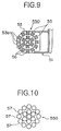
- pad protecting members 59 (The pad protecting members 59 are shown with two-dot chain line concerning only a part of the absorption sets 55 in Fig.11 for simplification.) in the shape of almost a cylinder, open in the lower direction, are provided at the portion near the lower end of the tube body 56, covering and protecting the periphery of the side of the pad 57.
- the upper side portion of the pad protecting member 59 is a taper portion 59a in the shape of a taper, making itself thinner for the upper hand.
- the inside of the pad 57 is connected and communicated with an air path 56c (Fig.6) which is the inside of the tube body 56 through the lower end of the tube body 56.
- Tubes 60 (are shown with a straight line, such as a dashed line in respective figures for simplification), which are expandable spiral tubes, are connected with the upper end side of the tube bodies 56 through joints 56b , communicating these air paths 56c and the inside of the tube 60 with each other.
- a horizontal tube support portion 61 in the shape of a plate is provided with the head frame 51, facing the head support portion 53 in the upper and lower direction above the head support portion 53.
- the end portion of the tube 60 of each absorption set 55 is connected with and supported by this tube support portion 61 through an appropriate joint 61a (which is omitted in Fig.7).
- a pressure transfer member 62 which is comprised of another tube is connected with each tube 60 through the joint 61a.
- the top end of the pressure transfer member 62 is connected with a vacuum pump 63 (The pressure transfer member 62 and the vacuum pump 63 are shown only in Fig.6.).
- a valve 65 free to open and close the inside of the pressure transfer member 62, is provided as shown in Fig.6.
- Each valve 65 is selectively free to be driven by a predetermined valve driving unit which is not shown.
- the absorption set aggregate 550 which is comprised of a plurality of absorption sets 55 are densely located, adjacent to each other such that these pads 57 form circular outline, as shown in Fig.10.
- the laser beam machining equipment 1 and the palletizing robot 20 are comprised as explained before. Then, the machining and the classification of a workpiece with the laser beam machining equipment 1 advance as shown in the following. That is, as shown in Fig.1, the raw material workpieces 70A, which are stored and piled at the raw material stocker 2, are taken out in order, and the raw material workpieces 70A taken out are carried to each laser beam machine 3 in order by the carrier robot 7.
- the raw material workpieces 70A carried in order are cut and machined in order at each laser beam machine 3, and the machined workpieces 70 finished machining at each laser beam machine 3, are carried to each classification head 5 in order by the carrier robot 7.
- the machined workpieces 70 carried to each classification head 5 are carried on each pallet 10 of each workpiece stocker 9 in order through the palletizing robot 20 with the routines explained hereinafter in detail.
- the palletizing robot 20 is positioned at a desired position in such a manner that the motor 22a is operated in the travel driving unit 22 provided with the suspension frame 21 so as to rotate and drive the gears 22b, 22b, then, the suspension frame 21 is moved and driven through the gears 22b, 22b and the racks 11b, 11b engaged with the gears 22b, 22b in the direction as shown by the arrow A along the guide rails 11, 11, so as to stop by the brake function of the travel driving unit 22. Then, the suspension frame 21 is positioned at the position corresponding to the machined workpiece 70 to be carried from now on, on the classification head 5 (the position corresponding to the direction as shown by the arrows A and B above the machined workpiece 70).
- the first frame 25 is moved and driven in the direction as shown by the arrows C and D along the movement rail 23 with respect to the suspension frame 21 in such a manner that the motor 26a is operated in the move driving unit 26 provided with the first frame 25 so as to rotate and drive the gear 26b, through the gears 26b and the rack 23a engaged with the gear 26b, and the first frame 25 is positioned at a desired position by the brake function of the move driving unit 26. Then, the first frame 25 is positioned at a position almost just above the machined workpiece 70 to be carried from now on, on the classification head 5.
- each absorption set aggregate 550 of four head units 45 is moved and positioned in horizontal two-dimensional direction above the machined workpiece 70, fitting in the form of the objective machined workpiece 70, for instance, as shown in Fig.5.
- This movement positioning is executed by performing (a) rotation and positioning of the suspension frame 35, (b) rotation and positioning of the arm 47 and (c) sliding movement and positioning of the head frame 51, explained hereinafter.
- each absorption set aggregate 550 of the four head units 45 is moved and positioned in a horizontal two-dimensional direction with respect to the stationary second frame 29 side, that is, with respect to the machined workpiece 70 on the classification head 5, and is positioned, fitting the shape of the machined workpiece 70 to be carried from now on, as shown in Fig.5, for instance.
- the motor 32a in the nut driving unit 32 of the first frame 25 is operated so as to rotate and drive each nut member 31 by the motor 32a, then each screw member 30 engaged with each nut member 31 is driven for the lower hand.
- the second frame 29 side is moved and driven in the lower direction (the direction as shown by the arrow F in the figure) with respect to the first frame 25 side, being guided through a plurality of rods 27 and the guide holes 25a inserting these rods.
- the moving and driving of the second frame 29 side with respect to the first frame 25 side is further continued. That is, the absorption set aggregate 550 of the four head units 45 is brought down, and the nut driving unit 32 is stopped to operate in such a state that each pad 57 of these absorption set aggregates 550 is abutted on the machined workpiece 70 on the classification head 5 so as to stop the movement of the second frame 29 side with respect to the first frame 25 side, as shown in Fig.5.
- the descent of the second frame 29 side with respect to the first frame 25 side may be continued to some degree after each pad 57 of the absorption set aggregate 550 is abutted on the machined workpiece 70, also.
- each absorption set 55 is free to move in the upper direction, relatively with respect to the head support portion 53, slidably moving the tube body 56. Then, the head support portion 53 is free to move in the lower direction, relatively with respect to each absorption set 55.
- each absorption set aggregate 550 of the four head units 45 are already positioned, fitting the shape of the objective machined workpiece 70, for instance, as shown in Fig.5, as mentioned before, these absorption set aggregates 550 are brought down to the machined workpiece 70, thereby many pads 57 of these absorption set aggregates 550 are appropriately abutted on the machined workpiece 70, for instance, as shown in Fig.5.
- the rotational axis CT2 which is rotational center of each arm 47 are located at intervals of 90 degrees with the rotational axis CT1 of the axis 33 suspending the suspension frame 35 as its center on the same circumference, and the length of each arm 47 is slightly shorter than the distance between the rotational axes CT1 and CT2.
- the boundary RF1-RF4 capable of positioning each absorption set aggregate 550 in a horizontal two-dimensional direction (in the level plane) is the boundary shown by the oblique line of Fig. 15 with each rotational axis CT2 as its standard, for instance (The two-dot chain line in Fig.15 shows the locus which the arm 47 and the absorption set aggregate 550 move).
- the boundary RG capable of positioning each absorption set aggregate 550 in a horizontal two-dimensional direction (in the level plane) with the rotational axis CT1 as its standard is the boundary inside the circle with the rotational axis CT1 as its center, as shown in Fig.15, for instance (shown by the dashed line of Fig.15).
- each absorption set aggregate 550 with respect to this machined workpiece 70 is appropriately performed as long as the machined workpiece 70 to be carried is in the boundary RG of the lower hand of the suspension frame 35.
- the absorption set aggregate 550 of the arms 47 is moved and positioned to the portion near the rotational axis CT1, gathering the top ends of each arm 47 to the portion near the rotational axis CT1, thereby the positioning of the absorption set aggregate 550 with respect to the small workpiece 70 in the shape of U near the rotational axis CT1 (Fig.16) and the circular workpiece 70 near the rotational axis CT1 (Fig.18) is executed.
- one absorption set aggregate 550 (the absorption set aggregate 550 of the lower side of the paper in the figure) is positioned further putting close to the rotational axis CT1 from the state of Fig.18, thereby the positioning of the absorption set aggregate 550 with respect to the small triangular workpiece near the rotational axis CT1 is executed.
- one arm 47 (the arm 47 of the lower side of the paper in the figure) is rotated and moved so as to keep away from the rotational axis CT1 from the state of Fig.18, and the absorption set aggregate 550 of the another arm 47 different from the precedent arm 47 (the arm 47 of the right side of the paper in the figure) is moved along the arm 47 so as to keep away from the rotational axis CT1, thereby the positioning of the absorption set aggregate 550 with respect the workpiece 70 having complex shape, which is long and narrow in the right and left direction of the paper in the figure (the long and narrow shape having a projection) is executed.
- two arms 47 are rotated and moved so as to keep away from the rotational axis CT1 from the state of Fig.19, thereby the positioning of the absorption set aggregate 550 with respect to the workpiece 70 having further complex shape in comparison with the shape in Fig.19 is executed.
- two arms 47 are rotated and moved from the state of Fig.18 so as to keep away from the rotational axis CT1, thereby the positioning of the absorption set aggregate 550 with respect to the workpiece 70 which is longer in the right and left direction of the paper in the figure, having a complex shape, in comparison with the shape in Fig.18 is executed.
- the four absorption set aggregates 550 are positioned with various patterns, which are not shown, thereby the positioning with respect to the various workpieces having a complex shape can be executed.
- the absorption of the workpiece 70 is performed.
- the vacuum pump 63 (Fig.6) is operated in advance and the valve 65 of each pressure transfer member 62 is in the state of being closed. Then, the valve 65 of each pressure transfer member 62 is driven so as to be in the state of being open in order to absorb the workpiece 70. By doing so, the pressure of the inside of each pad 57 connected with the vacuum pump 63 through the pressure transfer member 62, the tube 60 and the tube body 56 is decreased so as to generate suction force.
- each pad 57 abuts on the objective machined workpiece 70 as shown in Figs.5 and 13
- suction force generates between the pad 57 and the workpiece 70 so as to absorb the workpiece 70.
- the suction force to the workpiece 70 does not effectively generates in the pad 57 out of the workpiece 70, but in the pad 57 completely positioning on the workpiece 70, regardless of the pad 57 out of the workpiece 70, the airtightness between the pad 57 and the workpiece 70 is maintained and suction force effectively generates. Then, even if all of the pads 57 of the absorption set aggregate 550 is completely certainly not on the workpiece 70, the suction force necessary for certainly absorbing the workpiece 70 can be gotten. Therefore, even if the workpiece is one having a width smaller than the absorption set aggregate 550 or one having fine and complex shape, the suction force effectively generates so as to absorb the workpiece with no problem. Then, it is very convenient.
- the valve 65 When the workpiece is absorbed, the valve 65 is driven such that it becomes to be close state in the pressure transfer member 62 corresponding to the pads 57 out of the workpiece 70. By doing so, no vain suction force gives to the pad 57 to which effective suction force does not generate by the workpiece 70, and this energy can be saved. Besides, by doing so, the pad 57 out of the workpiece 70 can be prevented from absorbing ones excluding the workpiece 70 to be absorbed, such as the classification head 5 and the other workpieces 70, or from absorbing dust, so it is very convenient.
- the second frame 29 side is moved and driven with respect to the first frame 25 side in the upper direction (the direction as shown by the arrow E in the figure) by the nut driving unit 32 so as to raise the absorbed machined workpiece 70 to a predetermined height.
- the suspension frame 21 is moved and driven along the guide rails 11, 11 in the direction as shown in the arrow B by the travel driving unit 22 so as to stop the palletizing robot 20 at a desired position (the position matching to the pallet 10 of the workpiece stocker 9 to be delivered the absorbed machined workpiece 70 in the direction as shown by the arrows A and B).
- the first frame 25 side is moved and driven with respect to the suspension frame 21 along the movement rail 23 in the direction as shown by the arrows C and D by the move driving unit 26 so as to move the absorbed machined workpiece 70 to a desired position (the position almost just above the position on the pallet 10 to be delivered the machined workpiece 70). Then, the first frame 25 side is stopped so as to position.
- the axis 33 is rotated and driven with respect to the second frame 29 in the direction as shown by the arrows R1 and R2 in the figure with the rotational axis CT1 as its center by the rotation driving unit 36, and the suspension frame 35 side is rotated and driven in the direction as shown by the arrows R1 and R2 in the figure so as to adjust the direction of the absorbed machined workpiece 70 in a desired direction.
- the second frame 29 side is moved and driven with respect to the first frame 25 side in the lower direction (the direction as shown by the arrow F in the figure) by the nut driving unit 32 so as to bring the absorbed machined workpiece 70 down on the pallet 10. Furthermore, the second frame 29 side is moved and driven with respect to the first frame 25 side in the lower direction so as to further bring the absorbed workpiece 70 down.
- the workpiece 70 is put on a predetermined position on the pallet 10 (on the workpiece pile 700 already piled and put in the figure, but may be on the surface of the pallet 10).
- the valve 65 of each pressure transfer member 62 is made close so as to release the suction force between each pad 57 and the workpiece 70 and release the absorption of the workpiece 70.
- the absorbed carried workpiece 70 is delivered, putting on the workpiece pile 700 on the pallet 10.
- the movement and driving of the second frame 29 side with respect to the first frame 25 side in the lower direction may be continued to a degree.
- the head support portion 53 supporting a plurality of absorption sets 55 is further brought down as shown in Fig.14 (The absorption sets 55 absorbing the workpiece 70 are two in the center of the paper in the figure.).
- the head support portion 53 is free to move in the lower direction relatively with respect to each absorption set 55 as explained before, the head support portion 53 can be brought down without prevention by these absorption sets 55 even if each absorption set 55 abuts on the workpiece 70 and the like and is not further moved in the lower direction and stopped. Then, the absorption set 55 receives no unpremeditated power by the head support portion 53 and the like. That is, even if the movement quantity of the second frame 29 side with respect to the first frame 25 side is not specifically correct, the putting and the deliver of the absorbed machined workpiece 70 is appropriately performed. Then, it is very convenient.
- the putting position of the workpiece 70 to be put thereon (the height level) is different depending on the height of the workpiece pile 700 adready existent.
- the absorbed workpiece 70 can be put on and delivered to a predetermined putting position (the height level). Therefore, even if the movement quantity of the workpiece 70 in the up and down direction at the time of descending is always set constant for instance, the putting and deliver of the workpiece 70 in the height level different according to respective cases can be appropriately performed. Therefore, the control of the movement quantity in the up and down direction is made simple, then it is convenient.
- the carried workpieces 70 are put and delivered, making the workpiece piles 700 beside the already existent workpiece piles 700, as shown in Fig.12 and Fig.14, for instance, since it is necessary to classify many workpieces, effectively making use of the limited space on the pallet 10.
- the already existent another workpiece piles 700 exist, higher than the putting position to be put the absorbed workpiece 70 (the height level) just under the absorption sets 55 which does not absorb the workpiece 70 (two absorption sets 55 of the left side of the paper in Fig.14).
- the absorption set 55 which does not absorb the workpiece 70 (two absorption sets 55 of the left side of the paper in Fig.14) abuts on the upper face of another workpiece pile 700.
- the absorbing sets 55 abutting on the workpiece pile 700 remains to be in abutting condition, and is slidably moved in the upper direction relatively with respect to the head support portion 53. This is because each absorption set 55 is individually free to move in the up and down direction relatively with respect to the head support portion 53 in one absorption set aggregate 550.
- the absorption set 55 abutting on the workpiece pile 700 does not prevent the descent of the head support portion 53 side.
- these absorption sets 55 receive no unpremeditated force from the head support portion 53 side.
- the absorption sets 55 aborbing the workpiece 70 are brought down without hindrance, and the workpiece 70 can be put and delivered to a predetermined putting position. Even such a narrow place, the workpiece 70 can be appropriately delivered.
- the pad protecting member 59 in each absorption set 55 has a function of preventing from inadvertently absorbing outside dust when suction force generates in the pad 57, in addition to preventing from damaging by colliding a plurality of pads 57 with one another in the absorption set aggregate 550.
- the pad protecting member 59 of a plurality of pads 57 adjacent to one another has the taper portion 59a on its upper side. Therefore, when the pad protecting members 59, 59 adjacent to each other are shifted in up and down direction and are returned to the same height again, the lower end side of the pad protecting member 59 going down from the upper hand abuts on the taper portion 59a of the adjacent pad protecting member 59 which is in the lower hand, then the pad protecting member 59 slips down along this taper shape. Then, catching the pad protecting members 59, 59 each other can be prevented, so it is convenient.
- the palletizing robot 20 is traveled and moved in the direction as shown by the arrow A to the classification head 5 putting the workpiece to be carried next.
- the four absorption set aggregates 550 are positioned, fitting the objective machined workpiece 70 on the classification head 5 by the movement and positioning of the first frame 25 with respect to the suspension frame 21 in the direction as shown by the arrows C and D, (a) the rotation and positioning of the suspension frame 35, (b) the rotation and positioning of the arm 47 and (c) slidably movement and positioning of the head frame 51.
- a plurality of pads 57 of each absorption set aggregate 550 are abutted on the objective workpiece.
- the workpiece is absorbed by these pads 57.
- the palletizing robot 20 is traveled and moved to the workpiece stocker 9 in the direction as shown by the arrow B.
- the workpiece absorbed and carried by the rotation and positioning of the first frame 25 with respect to the suspension frame 21 in the direction as shown by the arrows C and D and the rotation and the positioning of the suspension frame 35 side is adjusted so as to match with the position to be put on the pallet 10 of the workpiece stocker 9.
- the absorbed workpiece is put on the putting position, and the absorption by the pads 57 is released. Then, the deliver finishes.
- the machined workpieces 70 put on each classification head 5 in order are absorbed and carried in order so as to be put and delivered on the pallet 10 of each workpiece stocker 9.
- each absorption set aggregate 550 can be appropriately positioned with respect to the workpiece having a complex shape, then, the workpiece can be absorbed and carried with no problem.
- each absorption set aggregate 550 is comprised of a plurality of absorption sets 55 which pads 57 are provided adjacent to each other. Then, suction force individually generates in the pads 57 of each absorption set 55.
- the workpiece can be appropriately absorbed by the remainder pads 57. Then, the fine complex workpiece having the width smaller than the absorption set aggregate 550, for instance, can be also absorbed, so it is very convenient.
- the tube body 56 and the pad 57 are fixedly connected in the absorption set 55.
- the tube body 56 and the pad 57 may be connected with an universal joint (not shown) or the like so as to rotate the pad 57 in all direction with respect to the tube body 56 (for instance, in the direction as shown by the arrow M1, M2, M3 or M4 shown in the right edge of the paper of Fig.11).
- the pads 57 are adjusted to the surface having the irregular portion by appropriately rotating each pad 57. Then, effective suction force can be generated between the pad 57 and the workpiece. So, the absorption and carry of the workpiece having an irregular portion can be performed.
- the absorption set aggregate 550 is free to move and position in a horizontal two-dimensional direction through the horizontal direction moving structure, which is comprised of the axis 33, the suspension frame 35, the rotation driving unit 36, the arm 47, the driving motor 49, the head frame 51, the slide driving unit 52 and the like.
- the horizontal direction moving structure may have another various structure.
- the arm having a flexible joint at a plurality of parts can be provided with the second frame 29 or the like so as to put the absorption set aggregate 550 on the top end side of this arm.
- the tube body 56 in the absorption set 55 is the member connecting and supporting the pad 57, being free to move in the up and down direction with respect to the head support portion 53, and is the absorbing means for transferring reduction of pressure from the vacuum pump 63 side to the pads 57.
- the slide member in the shape of a bar, which does not serve an absorbing means may be adopted in place of the tube body 56, and the absorbing means which is comprised of a tube or the like, connected with the vacuum pump 63 side, may be directly connected with the pad 57 connected with the slide member.
- the absorption head is applied in the laser beam machining equipment.
- the absorption head according to the present invention is not limited for only the laser beam machining equipment, and can be applied to the other type of machine tool equipment, also.
Landscapes
- Engineering & Computer Science (AREA)
- Mechanical Engineering (AREA)
- Manipulator (AREA)
- Magnetic Heads (AREA)
- Adornments (AREA)
- Electrical Discharge Machining, Electrochemical Machining, And Combined Machining (AREA)
- Jet Pumps And Other Pumps (AREA)
- Specific Conveyance Elements (AREA)
Abstract
Description
Claims (10)
- A workpiece absorption carrier unit, comprising:a machine body being free to move and drive at least in a horizontal direction;a head support rest provided with said machine body, being free to raise,one or more absorption means aggregates provided with said head support rest, being free to move and position in a horizontal two-dimensional direction through a horizontal direction moving structure;said absorption means aggregate having a plurality of absorption means provided such that absorption portions are adjacent to one another; andan absorption driving means connected with each of said absorption means.
- The workpiece absorption carrier unit as set forth in claim 1 wherein a plurality of said absorption means aggregates are provided, and these plural absorption means aggregates are free to individually move and position in a horizontal two-dimensional direction through said horizontal direction moving structure.
- The workpiece absorption carrier unit as set forth in claim 1 wherein respective absorption means of said absorption means aggregate are supported, being free to respectively individually move in up and down direction.
- The workpiece absorption carrier unit as set forth in claim 1 wherein said absorption driving means has an absorption control means for intermittently controlling absorption state of each absorption means.
- The workpiece absorption carrier unit as set forth in claim 1 wherein said horizontal direction moving structure has a frame provided with said head support rest, being free to rotate and position, an arm provided with said frame, being free to rotate and position and a head putting portion for putting said absorption means aggregates, provided with said arm, being free to move and position in a horizontal direction.
- An absorption head, comprising:a head body;a plurality of absorption means, provided with said head body;a slide portion in the shape of a bar provided with each of said absorption means, movably supported in an axial center direction with respect to said head body, being independent of another absorption means;an absorption portion densely located, being adjacent to one another in non-absorption state of an object, provided with a top end of each of said slide portions;an air absorption means connected with each of said absorption portions; andan intermittent absorption control means provided with said air absorption means, capable of individually on-off controlling of absorption operation of air to each of said absorption portions.
- The absorption head as set forth in claim 6 wherein said slide portion in the shape of a bar is formed in the shape of a hollow tube, having air path therein, and said air path comprises a part of said air absorption means for absorbing air from each of said absorption portions.
- The absorption head as set forth in claim 6 wherein each of said absorption portions is supported, rotatably in all direction with respect to said slide portion in the shape of a bar.
- The absorption head as set forth in claim 6 wherein a moving means of said head body is provided with said head body.
- The absorption head as set forth in claim 6 wherein each of said absorption portions has a cover means for covering each of said absorption portions and a taper portion is formed on said head body side of said cover means.
Priority Applications (1)
| Application Number | Priority Date | Filing Date | Title |
|---|---|---|---|
| EP04011753A EP1452267B1 (en) | 1998-10-19 | 1999-10-15 | Carrier unit for holding a workpiece by vacuum and vacuum holding head |
Applications Claiming Priority (4)
| Application Number | Priority Date | Filing Date | Title |
|---|---|---|---|
| JP31541498 | 1998-10-19 | ||
| JP31541398 | 1998-10-19 | ||
| JP10315414A JP2000127076A (en) | 1998-10-19 | 1998-10-19 | Suction head |
| JP31541398A JP3895483B2 (en) | 1998-10-19 | 1998-10-19 | Workpiece suction transfer device |
Related Child Applications (1)
| Application Number | Title | Priority Date | Filing Date |
|---|---|---|---|
| EP04011753A Division EP1452267B1 (en) | 1998-10-19 | 1999-10-15 | Carrier unit for holding a workpiece by vacuum and vacuum holding head |
Publications (3)
| Publication Number | Publication Date |
|---|---|
| EP0995542A2 true EP0995542A2 (en) | 2000-04-26 |
| EP0995542A3 EP0995542A3 (en) | 2002-10-16 |
| EP0995542B1 EP0995542B1 (en) | 2005-04-06 |
Family
ID=26568294
Family Applications (2)
| Application Number | Title | Priority Date | Filing Date |
|---|---|---|---|
| EP04011753A Expired - Lifetime EP1452267B1 (en) | 1998-10-19 | 1999-10-15 | Carrier unit for holding a workpiece by vacuum and vacuum holding head |
| EP99120505A Expired - Lifetime EP0995542B1 (en) | 1998-10-19 | 1999-10-15 | Carrier unit for workpiece sucking and holding means |
Family Applications Before (1)
| Application Number | Title | Priority Date | Filing Date |
|---|---|---|---|
| EP04011753A Expired - Lifetime EP1452267B1 (en) | 1998-10-19 | 1999-10-15 | Carrier unit for holding a workpiece by vacuum and vacuum holding head |
Country Status (5)
| Country | Link |
|---|---|
| US (1) | US6311966B1 (en) |
| EP (2) | EP1452267B1 (en) |
| KR (1) | KR100481020B1 (en) |
| AT (2) | ATE387285T1 (en) |
| DE (2) | DE69924578T2 (en) |
Cited By (6)
| Publication number | Priority date | Publication date | Assignee | Title |
|---|---|---|---|---|
| EP1249398A1 (en) * | 2001-04-09 | 2002-10-16 | FPS Food Processing Systems B.V. | Suction cup device |
| EP1286168A4 (en) * | 2001-02-08 | 2005-08-10 | Seiko Epson Corp | ELEMENT MOVING DEVICE, ELEMENT MOTION MEMBER CONTROL METHOD, INTEGRATED CIRCUIT INSPECTION METHOD, INTEGRATED CIRCUIT MANIPULATOR, AND INTEGRATED CIRCUIT INSPECTION DEVICE |
| EP1967301A1 (en) | 2007-03-06 | 2008-09-10 | Trumpf Sachsen GmbH | Machine assembly for processing plate-shaped workpieces with a processing unit and a handling device for processed products |
| CN106670657A (en) * | 2015-11-11 | 2017-05-17 | 上海酷铃自动化设备有限公司 | Vacuum suction cup mechanical carrying device plate carrying device |
| CN107640885A (en) * | 2017-09-19 | 2018-01-30 | 深圳市华星光电技术有限公司 | A kind of offal timber clamp device |
| CN109809184A (en) * | 2019-03-21 | 2019-05-28 | 大族激光科技产业集团股份有限公司 | A kind of handling equipment |
Families Citing this family (13)
| Publication number | Priority date | Publication date | Assignee | Title |
|---|---|---|---|---|
| DE69937810T2 (en) * | 1998-12-25 | 2008-06-26 | Yamazaki Mazak K.K. | Unit for parts classification |
| US6817145B2 (en) * | 2002-08-28 | 2004-11-16 | Chung-Teng Chen | Glasshouse strut |
| JP5008252B2 (en) * | 2004-05-18 | 2012-08-22 | パナソニック株式会社 | Liquid fuel container for fuel cell and fuel cell system |
| US20100126320A1 (en) * | 2008-11-21 | 2010-05-27 | Trumpf, Inc. | Vacuum based part separation |
| JP5505713B2 (en) * | 2010-04-26 | 2014-05-28 | 株式会社Sumco | Polishing liquid distributor and polishing apparatus provided with the same |
| CN102909499A (en) * | 2011-08-03 | 2013-02-06 | 重庆长安凌云汽车零部件有限公司 | Intelligent robot welding workstation for fixing apparatuses of child restraint systems of automobiles |
| CN103367217B (en) * | 2012-04-11 | 2016-08-24 | 上海微电子装备有限公司 | A kind of silicon-chip absorption device and absorption method thereof |
| CN104051290B (en) * | 2013-03-12 | 2018-03-09 | 松下知识产权经营株式会社 | Engagement device and film-form substrate holding unit |
| CN107627242B (en) * | 2017-10-20 | 2023-07-11 | 昆山佰奥智能装备股份有限公司 | Separable carrier positioning mechanism |
| USD864263S1 (en) * | 2018-04-26 | 2019-10-22 | Jinan Jinqiang Laser CNC Equipment Co., Ltd | Loader machine |
| JP7156067B2 (en) * | 2019-02-07 | 2022-10-19 | トヨタ自動車株式会社 | Gripping error correction method, device, and program |
| CN113579725A (en) * | 2021-07-30 | 2021-11-02 | 博众精工科技股份有限公司 | Positioning transfer device |
| CN117800089B (en) * | 2024-01-29 | 2025-02-11 | 北京沃华慧通测控技术有限公司 | Annular workpiece conveying device and conveying method |
Family Cites Families (9)
| Publication number | Priority date | Publication date | Assignee | Title |
|---|---|---|---|---|
| CA1042281A (en) * | 1974-07-22 | 1978-11-14 | Cominco Ltd. | Method and apparatus for dust control treatment |
| DE3333301A1 (en) * | 1983-09-15 | 1985-03-28 | Otto Hänsel GmbH, 3000 Hannover | DEVICE FOR INLAYING CONFECTIONERY PIECES LIKE CHOCOLATES, SWEETS, CHOCOLATE TABLETS OD. DGL. IN BOXES OR PACKING INSERTS |
| US4684113A (en) * | 1984-09-28 | 1987-08-04 | The Boeing Company | Universal holding fixture |
| NL9200001A (en) * | 1992-01-02 | 1993-08-02 | Rohaco Ind Handling B V | DEVICE FOR GRIPPING AND MOVING OBJECTS. |
| JP3070344B2 (en) * | 1992-07-31 | 2000-07-31 | トヨタ自動車株式会社 | Cleaning equipment for cutting plate work for press |
| ES2075800B1 (en) * | 1993-10-14 | 1998-07-16 | Torres Martinez M | INSTALLATION FOR THE TRANSPORT AND TURNING OF LARGE PARTS. |
| US5544968A (en) * | 1995-06-02 | 1996-08-13 | Advanced Machine & Engineering Co. | Lockable ball joint apparatus |
| NL1006715C2 (en) * | 1997-08-04 | 1999-02-08 | Food Processing Systems | Product transfer device as well as an assembly comprising such a product transfer device. |
| US5975183A (en) * | 1998-03-23 | 1999-11-02 | Northrop Grumman Corporation | Repair pressure applicator for in the field damaged aircraft |
-
1999
- 1999-10-15 AT AT04011753T patent/ATE387285T1/en not_active IP Right Cessation
- 1999-10-15 EP EP04011753A patent/EP1452267B1/en not_active Expired - Lifetime
- 1999-10-15 AT AT99120505T patent/ATE292542T1/en not_active IP Right Cessation
- 1999-10-15 EP EP99120505A patent/EP0995542B1/en not_active Expired - Lifetime
- 1999-10-15 DE DE69924578T patent/DE69924578T2/en not_active Expired - Lifetime
- 1999-10-15 DE DE69938260T patent/DE69938260T2/en not_active Expired - Fee Related
- 1999-10-18 US US09/420,116 patent/US6311966B1/en not_active Expired - Lifetime
- 1999-10-19 KR KR10-1999-0045373A patent/KR100481020B1/en not_active Expired - Fee Related
Cited By (10)
| Publication number | Priority date | Publication date | Assignee | Title |
|---|---|---|---|---|
| EP1286168A4 (en) * | 2001-02-08 | 2005-08-10 | Seiko Epson Corp | ELEMENT MOVING DEVICE, ELEMENT MOTION MEMBER CONTROL METHOD, INTEGRATED CIRCUIT INSPECTION METHOD, INTEGRATED CIRCUIT MANIPULATOR, AND INTEGRATED CIRCUIT INSPECTION DEVICE |
| US6984973B2 (en) | 2001-02-08 | 2006-01-10 | Seiko Epson Corporation | Part transfer apparatus, control method for part transfer apparatus, IC test method, IC handler, and IC test apparatus |
| EP1249398A1 (en) * | 2001-04-09 | 2002-10-16 | FPS Food Processing Systems B.V. | Suction cup device |
| EP1967301A1 (en) | 2007-03-06 | 2008-09-10 | Trumpf Sachsen GmbH | Machine assembly for processing plate-shaped workpieces with a processing unit and a handling device for processed products |
| US8074975B2 (en) | 2007-03-06 | 2011-12-13 | Trumpf Sachsen Gmbh | Mechanical arrangement for processing plate-like workpieces |
| CN106670657A (en) * | 2015-11-11 | 2017-05-17 | 上海酷铃自动化设备有限公司 | Vacuum suction cup mechanical carrying device plate carrying device |
| CN106670657B (en) * | 2015-11-11 | 2019-04-02 | 上海酷铃自动化设备有限公司 | Vacuum chuck machinery handling device plate handling device |
| CN107640885A (en) * | 2017-09-19 | 2018-01-30 | 深圳市华星光电技术有限公司 | A kind of offal timber clamp device |
| CN109809184A (en) * | 2019-03-21 | 2019-05-28 | 大族激光科技产业集团股份有限公司 | A kind of handling equipment |
| CN109809184B (en) * | 2019-03-21 | 2021-05-14 | 大族激光科技产业集团股份有限公司 | A loading and unloading device |
Also Published As
| Publication number | Publication date |
|---|---|
| ATE292542T1 (en) | 2005-04-15 |
| KR20000029186A (en) | 2000-05-25 |
| ATE387285T1 (en) | 2008-03-15 |
| KR100481020B1 (en) | 2005-04-07 |
| US6311966B1 (en) | 2001-11-06 |
| EP0995542B1 (en) | 2005-04-06 |
| DE69924578D1 (en) | 2005-05-12 |
| EP1452267B1 (en) | 2008-02-27 |
| DE69924578T2 (en) | 2006-02-09 |
| DE69938260D1 (en) | 2008-04-10 |
| EP1452267A1 (en) | 2004-09-01 |
| DE69938260T2 (en) | 2009-03-05 |
| EP0995542A3 (en) | 2002-10-16 |
Similar Documents
| Publication | Publication Date | Title |
|---|---|---|
| EP0995542B1 (en) | Carrier unit for workpiece sucking and holding means | |
| US5401128A (en) | Octahedral machine with a hexapodal triangular servostrut section | |
| US6745455B2 (en) | Automatic milling and drilling machine | |
| CN110238553B (en) | A skylight tailor welding machine | |
| US20180250781A1 (en) | Autonomous production line | |
| EP1712337B1 (en) | Machining centre with two operating units with part handling means | |
| JP7270542B2 (en) | Conveying apparatus, method and computer program product for loading into and out of at least one material machining unit | |
| JP7301001B2 (en) | Travel system and gear cutting machine | |
| JPS6352952A (en) | Machining center with inclinable vacuum holding work table | |
| US20080181759A1 (en) | Workpiece handling device | |
| JP3874872B2 (en) | Spindle head 3-axis moving CNC lathe | |
| EP4552776A1 (en) | Cutting machine and related operating method | |
| JP3895483B2 (en) | Workpiece suction transfer device | |
| EP1469365B1 (en) | Parts classification unit | |
| EP4090493A1 (en) | System for processing a workpiece | |
| JP4490449B2 (en) | Workpiece suction transfer device | |
| CN116809838A (en) | Frame cross beam riveting system and riveting method | |
| CN208759110U (en) | Opposite type multistation loading and unloading storage arrangement | |
| JP3558988B2 (en) | Welding method and welding system | |
| CN211991398U (en) | A mobile phone mid-board turntable copper sheet welding equipment | |
| CN107900796A (en) | Full-automatic polishing machine and polishing method | |
| JP6469540B2 (en) | Machining center | |
| CN118927033A (en) | A blade grinding production line | |
| JP3911441B2 (en) | Work delivery device | |
| CN212981561U (en) | Steering device |
Legal Events
| Date | Code | Title | Description |
|---|---|---|---|
| PUAI | Public reference made under article 153(3) epc to a published international application that has entered the european phase |
Free format text: ORIGINAL CODE: 0009012 |
|
| AK | Designated contracting states |
Kind code of ref document: A2 Designated state(s): AT BE CH CY DE DK ES FI FR GB GR IE IT LI LU MC NL PT SE |
|
| AX | Request for extension of the european patent |
Free format text: AL;LT;LV;MK;RO;SI |
|
| PUAL | Search report despatched |
Free format text: ORIGINAL CODE: 0009013 |
|
| AK | Designated contracting states |
Kind code of ref document: A3 Designated state(s): AT BE CH CY DE DK ES FI FR GB GR IE IT LI LU MC NL PT SE |
|
| AX | Request for extension of the european patent |
Free format text: AL;LT;LV;MK;RO;SI |
|
| 17P | Request for examination filed |
Effective date: 20030416 |
|
| AKX | Designation fees paid |
Designated state(s): AT BE CH CY DE DK ES FI FR GB GR IE IT LI LU MC NL PT SE |
|
| 17Q | First examination report despatched |
Effective date: 20031114 |
|
| GRAP | Despatch of communication of intention to grant a patent |
Free format text: ORIGINAL CODE: EPIDOSNIGR1 |
|
| RTI1 | Title (correction) |
Free format text: CARRIER UNIT FOR WORKPIECE SUCKING AND HOLDING MEANS |
|
| GRAS | Grant fee paid |
Free format text: ORIGINAL CODE: EPIDOSNIGR3 |
|
| GRAA | (expected) grant |
Free format text: ORIGINAL CODE: 0009210 |
|
| AK | Designated contracting states |
Kind code of ref document: B1 Designated state(s): AT BE CH CY DE DK ES FI FR GB GR IE IT LI LU MC NL PT SE |
|
| PG25 | Lapsed in a contracting state [announced via postgrant information from national office to epo] |
Ref country code: NL Free format text: LAPSE BECAUSE OF FAILURE TO SUBMIT A TRANSLATION OF THE DESCRIPTION OR TO PAY THE FEE WITHIN THE PRESCRIBED TIME-LIMIT Effective date: 20050406 Ref country code: LI Free format text: LAPSE BECAUSE OF FAILURE TO SUBMIT A TRANSLATION OF THE DESCRIPTION OR TO PAY THE FEE WITHIN THE PRESCRIBED TIME-LIMIT Effective date: 20050406 Ref country code: FI Free format text: LAPSE BECAUSE OF FAILURE TO SUBMIT A TRANSLATION OF THE DESCRIPTION OR TO PAY THE FEE WITHIN THE PRESCRIBED TIME-LIMIT Effective date: 20050406 Ref country code: CH Free format text: LAPSE BECAUSE OF FAILURE TO SUBMIT A TRANSLATION OF THE DESCRIPTION OR TO PAY THE FEE WITHIN THE PRESCRIBED TIME-LIMIT Effective date: 20050406 Ref country code: BE Free format text: LAPSE BECAUSE OF FAILURE TO SUBMIT A TRANSLATION OF THE DESCRIPTION OR TO PAY THE FEE WITHIN THE PRESCRIBED TIME-LIMIT Effective date: 20050406 Ref country code: AT Free format text: LAPSE BECAUSE OF FAILURE TO SUBMIT A TRANSLATION OF THE DESCRIPTION OR TO PAY THE FEE WITHIN THE PRESCRIBED TIME-LIMIT Effective date: 20050406 |
|
| RAP1 | Party data changed (applicant data changed or rights of an application transferred) |
Owner name: YAMAZAKI MAZAK KABUSHIKI KAISHA |
|
| REG | Reference to a national code |
Ref country code: GB Ref legal event code: FG4D |
|
| REG | Reference to a national code |
Ref country code: CH Ref legal event code: EP |
|
| REG | Reference to a national code |
Ref country code: IE Ref legal event code: FG4D |
|
| REF | Corresponds to: |
Ref document number: 69924578 Country of ref document: DE Date of ref document: 20050512 Kind code of ref document: P |
|
| PG25 | Lapsed in a contracting state [announced via postgrant information from national office to epo] |
Ref country code: SE Free format text: LAPSE BECAUSE OF FAILURE TO SUBMIT A TRANSLATION OF THE DESCRIPTION OR TO PAY THE FEE WITHIN THE PRESCRIBED TIME-LIMIT Effective date: 20050706 Ref country code: GR Free format text: LAPSE BECAUSE OF FAILURE TO SUBMIT A TRANSLATION OF THE DESCRIPTION OR TO PAY THE FEE WITHIN THE PRESCRIBED TIME-LIMIT Effective date: 20050706 Ref country code: DK Free format text: LAPSE BECAUSE OF FAILURE TO SUBMIT A TRANSLATION OF THE DESCRIPTION OR TO PAY THE FEE WITHIN THE PRESCRIBED TIME-LIMIT Effective date: 20050706 |
|
| PG25 | Lapsed in a contracting state [announced via postgrant information from national office to epo] |
Ref country code: ES Free format text: LAPSE BECAUSE OF FAILURE TO SUBMIT A TRANSLATION OF THE DESCRIPTION OR TO PAY THE FEE WITHIN THE PRESCRIBED TIME-LIMIT Effective date: 20050717 |
|
| PG25 | Lapsed in a contracting state [announced via postgrant information from national office to epo] |
Ref country code: PT Free format text: LAPSE BECAUSE OF FAILURE TO SUBMIT A TRANSLATION OF THE DESCRIPTION OR TO PAY THE FEE WITHIN THE PRESCRIBED TIME-LIMIT Effective date: 20050908 |
|
| NLV1 | Nl: lapsed or annulled due to failure to fulfill the requirements of art. 29p and 29m of the patents act | ||
| REG | Reference to a national code |
Ref country code: CH Ref legal event code: PL |
|
| PG25 | Lapsed in a contracting state [announced via postgrant information from national office to epo] |
Ref country code: CY Free format text: LAPSE BECAUSE OF FAILURE TO SUBMIT A TRANSLATION OF THE DESCRIPTION OR TO PAY THE FEE WITHIN THE PRESCRIBED TIME-LIMIT Effective date: 20051015 |
|
| PG25 | Lapsed in a contracting state [announced via postgrant information from national office to epo] |
Ref country code: IE Free format text: LAPSE BECAUSE OF NON-PAYMENT OF DUE FEES Effective date: 20051017 |
|
| PG25 | Lapsed in a contracting state [announced via postgrant information from national office to epo] |
Ref country code: MC Free format text: LAPSE BECAUSE OF NON-PAYMENT OF DUE FEES Effective date: 20051031 Ref country code: LU Free format text: LAPSE BECAUSE OF NON-PAYMENT OF DUE FEES Effective date: 20051031 |
|
| PLBE | No opposition filed within time limit |
Free format text: ORIGINAL CODE: 0009261 |
|
| STAA | Information on the status of an ep patent application or granted ep patent |
Free format text: STATUS: NO OPPOSITION FILED WITHIN TIME LIMIT |
|
| ET | Fr: translation filed | ||
| 26N | No opposition filed |
Effective date: 20060110 |
|
| REG | Reference to a national code |
Ref country code: IE Ref legal event code: MM4A |
|
| PGFP | Annual fee paid to national office [announced via postgrant information from national office to epo] |
Ref country code: DE Payment date: 20091008 Year of fee payment: 11 |
|
| PGFP | Annual fee paid to national office [announced via postgrant information from national office to epo] |
Ref country code: IT Payment date: 20091017 Year of fee payment: 11 Ref country code: GB Payment date: 20091014 Year of fee payment: 11 Ref country code: FR Payment date: 20091029 Year of fee payment: 11 |
|
| GBPC | Gb: european patent ceased through non-payment of renewal fee |
Effective date: 20101015 |
|
| PG25 | Lapsed in a contracting state [announced via postgrant information from national office to epo] |
Ref country code: FR Free format text: LAPSE BECAUSE OF NON-PAYMENT OF DUE FEES Effective date: 20101102 |
|
| REG | Reference to a national code |
Ref country code: FR Ref legal event code: ST Effective date: 20110630 |
|
| REG | Reference to a national code |
Ref country code: DE Ref legal event code: R119 Ref document number: 69924578 Country of ref document: DE Effective date: 20110502 |
|
| PG25 | Lapsed in a contracting state [announced via postgrant information from national office to epo] |
Ref country code: GB Free format text: LAPSE BECAUSE OF NON-PAYMENT OF DUE FEES Effective date: 20101015 |
|
| PG25 | Lapsed in a contracting state [announced via postgrant information from national office to epo] |
Ref country code: IT Free format text: LAPSE BECAUSE OF NON-PAYMENT OF DUE FEES Effective date: 20101015 |
|
| PG25 | Lapsed in a contracting state [announced via postgrant information from national office to epo] |
Ref country code: DE Free format text: LAPSE BECAUSE OF NON-PAYMENT OF DUE FEES Effective date: 20110502 |