EP0997399A2 - Transportbehälter - Google Patents
Transportbehälter Download PDFInfo
- Publication number
- EP0997399A2 EP0997399A2 EP99120883A EP99120883A EP0997399A2 EP 0997399 A2 EP0997399 A2 EP 0997399A2 EP 99120883 A EP99120883 A EP 99120883A EP 99120883 A EP99120883 A EP 99120883A EP 0997399 A2 EP0997399 A2 EP 0997399A2
- Authority
- EP
- European Patent Office
- Prior art keywords
- transport container
- transport
- locking device
- frame
- receiving part
- Prior art date
- Legal status (The legal status is an assumption and is not a legal conclusion. Google has not performed a legal analysis and makes no representation as to the accuracy of the status listed.)
- Withdrawn
Links
Images


Classifications
-
- B—PERFORMING OPERATIONS; TRANSPORTING
- B65—CONVEYING; PACKING; STORING; HANDLING THIN OR FILAMENTARY MATERIAL
- B65D—CONTAINERS FOR STORAGE OR TRANSPORT OF ARTICLES OR MATERIALS, e.g. BAGS, BARRELS, BOTTLES, BOXES, CANS, CARTONS, CRATES, DRUMS, JARS, TANKS, HOPPERS, FORWARDING CONTAINERS; ACCESSORIES, CLOSURES, OR FITTINGS THEREFOR; PACKAGING ELEMENTS; PACKAGES
- B65D85/00—Containers, packaging elements or packages, specially adapted for particular articles or materials
- B65D85/30—Containers, packaging elements or packages, specially adapted for particular articles or materials for articles particularly sensitive to damage by shock or pressure
- B65D85/38—Containers, packaging elements or packages, specially adapted for particular articles or materials for articles particularly sensitive to damage by shock or pressure for delicate optical, measuring, calculating or control apparatus
-
- B—PERFORMING OPERATIONS; TRANSPORTING
- B65—CONVEYING; PACKING; STORING; HANDLING THIN OR FILAMENTARY MATERIAL
- B65D—CONTAINERS FOR STORAGE OR TRANSPORT OF ARTICLES OR MATERIALS, e.g. BAGS, BARRELS, BOTTLES, BOXES, CANS, CARTONS, CRATES, DRUMS, JARS, TANKS, HOPPERS, FORWARDING CONTAINERS; ACCESSORIES, CLOSURES, OR FITTINGS THEREFOR; PACKAGING ELEMENTS; PACKAGES
- B65D7/00—Containers having bodies formed by interconnecting or uniting two or more rigid, or substantially rigid, components made wholly or mainly of metal
- B65D7/02—Containers having bodies formed by interconnecting or uniting two or more rigid, or substantially rigid, components made wholly or mainly of metal characterised by shape
- B65D7/06—Containers having bodies formed by interconnecting or uniting two or more rigid, or substantially rigid, components made wholly or mainly of metal characterised by shape of polygonal cross-section, e.g. tins, boxes
-
- B—PERFORMING OPERATIONS; TRANSPORTING
- B65—CONVEYING; PACKING; STORING; HANDLING THIN OR FILAMENTARY MATERIAL
- B65D—CONTAINERS FOR STORAGE OR TRANSPORT OF ARTICLES OR MATERIALS, e.g. BAGS, BARRELS, BOTTLES, BOXES, CANS, CARTONS, CRATES, DRUMS, JARS, TANKS, HOPPERS, FORWARDING CONTAINERS; ACCESSORIES, CLOSURES, OR FITTINGS THEREFOR; PACKAGING ELEMENTS; PACKAGES
- B65D2585/00—Containers, packaging elements or packages specially adapted for particular articles or materials
- B65D2585/68—Containers, packaging elements or packages specially adapted for particular articles or materials for machines, engines, or vehicles in assembled or dismantled form
- B65D2585/6802—Containers, packaging elements or packages specially adapted for particular articles or materials for machines, engines, or vehicles in assembled or dismantled form specific machines, engines or vehicles
- B65D2585/6835—Containers, packaging elements or packages specially adapted for particular articles or materials for machines, engines, or vehicles in assembled or dismantled form specific machines, engines or vehicles audio-visual devices
- B65D2585/6837—Containers, packaging elements or packages specially adapted for particular articles or materials for machines, engines, or vehicles in assembled or dismantled form specific machines, engines or vehicles audio-visual devices tv or computers
Definitions
- the invention relates to a transport container for electronic goods, especially PC and its accessories, typewriters and the like, which are free of any protective packaging, in particular from the manufacturer's packaging.
- Transport containers are usually made of light metal available in various sizes to accommodate the stowed in it Protection against harmful external feet, such as dust, Splash water, blows, etc., offer. Because of the usual very long Distribution channels must be the transport boxes for all goods have sufficient stability and also low Have empty weight.
- transport container crates are made of aluminum for this used.
- the inside of the shipping container is mostly accessible via a removable cover, which is often also via the Can be swiveled perpendicular to the bottom of the container into a stop position and thus can be determined .
- the inner surfaces of the transport container lined with foam and, if necessary, partitions fed, which are also provided with foam and the corresponding Space essentially suitable for the goods to be transported delimit.
- computers In the case of computers, for example, it is necessary to follow the Completion of the hardware in a further sales stage at a software provider for the end customer with special software equip. To do this, the computers would have to be included after unpacking the appropriate cables are connected to the necessary Establish connections with the corresponding devices. After this The computers will be configured with the monitors, printers, Scanners and the like. Connected packed ready for transport to later unpacked and set up ready for use by the end customer become.
- the invention is based on the object Functionally expand the transport container so that especially a Handling of the goods to be transported, in particular computer components, is made possible essentially from all sides without remove them from the shipping container.
- This object is achieved by the features specified in claim 1 solved.
- This is a frame based Transport container, which has wing doors on its side surfaces, which allow access to the transport goods. So is a Handling of the goods in the transport container easily possible through the open areas of the transport container, such as e.g. plugging in connecting cables, etc. after editing the goods to be transported remain in the transport container and can be transported further without, for example, computer stations the connections of the individual modules again separate or rearrange within the transport container.
- the transport container according to claim 2 results in an advantageous embodiment, the two double doors on opposite sides, preferably attached to the two parallel long sides, whereby optimal stability of the transport container because of the Panels provide side areas on the one hand and an optimal one on the other Accessibility through the large, open side areas is guaranteed .
- the wing doors interfere with Do not open each other and therefore also open when open no hindrance to those on the transport goods in the transport container working people.
- the transport container can easily be any as a modular construction cuboid shape in changeable dimensions, without having to make design changes.
- the preferred embodiments according to claims 3 to 7 an easy to manufacture, light and stable frame for the Transport container safe.
- the structure of the frame enables due to its skeletal structure, any arrangement of the Panels as well as the double wing doors. Attention is also paid to specifically lightweight materials, e.g. Aluminum for the pipes of the frame and plastic for the pipe connector, too use.
- the advantageous use of square tubes for that Roh system allows for mounting surfaces for attaching To provide structural components on the frame.
- has a square cross-sectional shape of the square tube good Stiffness values.
- a high-performance adhesive tape can be used to fasten the panels to the support webs or fluid adhesive, using rivets, Screws and the like. Used to support the attachment of the plates can be.
- This teaching leads to high strength a light overall weight of the transport container. Especially It is advantageous to make the support web in one piece with the square tube to train.
- Adequate stability, especially against external shocks on the transport container is by the teaching of claim 9 reached. With this structure it becomes a specific light and stable Plate for the side, roof and floor areas or for the double wing doors created.
- the frame can preferably hinge joints, in particular Bar hinges or double bar hinges, used be attached to the outer surface of the square tubes are. These allow the doors to swing open by up to 270 °.
- Beams can be provided to reinforce areas with tarpaulins be a stiffening of the tarpaulin also with regard to the cause the air cushions to inflate.
- transport container In the development of the transport container according to claim 10 an easily adaptable protective jacket for those stored in the transport container Goods provided. They ensure safe transport Transport goods are surrounded by air cushions that vary in shape Easily adjust the transported goods and after deflating them are removable.
- a transport container system according to claim 19 are transport containers according to the invention one above the other stacked and possibly stored on a traveling frame.
- the transport containers are preferably one above the other or on one another other system module can be coupled such that a stable transport container system unit arises.
- a transport container system unit arises.
- an inventive Transport container provided a locking device his.
- the locking device according to the invention with two together to be coupled, separate components, the engagement part and the receiving part, trained.
- Under engagement part is an element of To understand locking device that when locking the Transport container with the transport component to be coupled in the Receiving part takes hold.
- the receiving part takes part of the engagement part when locking in see either the engaging part at least partially inside a tubular element of the transport container housed or arranged in the system module is. Or that which interacts with the engagement part in a lockable manner Receiving part is arranged in the system module or at least partially inside a tubular element of the transport container assembled.
- the engagement part comprises a swivel hook which can be actuated from the outside from a passive position pivoted into the tubular element can be brought into an active pivoted position in which the Swivel hook comes into engagement with the receiving part.
- the recording part includes a bolt and a locking pin that the with secures the bolt locked swivel hook in its active position.
- the locking pin is acted upon by a spring which holds it in whose securing position holds.
- the locking pin can be from the outside are pulled against the spring force from the securing position, around the swivel hook from its active position to its passive Swivel position.
- Both the engaging part and the receiving part preferably have the swivel hook or the bolt and the locking pin receiving insert plate. This ensures a stable connection with the tubular elements and thus a robust locking.
- a preferred transport container is formed when this is both a Engagement part to lock another transport component with itself, as well as a receiving part to be attached to a corresponding one Engagement part provided transport component to be coupled.
- the two components - Engagement part and receiving part - in the frame of the Transport container are at least partially to accommodate.
- the engaging and receiving part are in adjacent pipe elements, preferably in the adjacent transverse or longitudinal pipe elements a cuboid frame, the transport containers to be coupled arranged.
- Immediate coupling and decoupling of a preferred transport container comes with a pair of engaging parts on the bottom or roof side of the transport container and a pair of receiving parts on the Roof side or floor side created.
- Both the engaging part and the receiving part are with the corresponding one Pipe element of the transport container over an insert plate mechanically firmly connected.
- a pair Locking devices are provided on the cross-tube elements.
- a preferred transport container system is made up of three stacked one on top of the other inventive transport container formed, among themselves coupled with a locking device according to the invention are.
- the transport container at the bottom is over a locking device according to the invention with a traveling frame connected.
- the cuboid frame 1 shown in FIG. 1 has a floor area 2, a roof area 3 and four side areas 4, 5, 6 and 7 on that in two parallel lengths 4, 5 and two parallel latitude side areas 6, 7 can be divided.
- the frame 1 consists of a pipe system 8, its pipes on the edges of the cuboid having.
- the pipes used for the pipe system are square pipes 9, of which there are three different types: four vertical square tubes 10, four length 4-square tubes 11 and four cross-square tubes 12th
- each a vertical, transverse and Lengths 4-square tube 10,11,12 connects with each other, the tubes always make a right angle with each other.
- the pipe connector 13 has three outlets 14 to which the respective Pipes are pushed on and fastened.
- a 2-component epoxy resin adhesive used, rivets additionally as a fuse can be used.
- the pipe connector includes one Plastic cover, in which a steel core is inserted to reinforce it is.
- FIGS. 2 and 3 Two cross-sectional shapes of the square tube 9 can be seen in FIGS. 2 and 3, the square tube 9 with its square hollow cross section (Side length a) is made of aluminum.
- the square tube 9 has two outer surfaces 15, 16 and two at least partially have side surfaces in the interior of the transport container 17.18. On the side surfaces 17, 18 there is in each case a support web 19 arranged in one piece with the tube 9.
- the footbridge 19 includes a support surface 20 for the walls, not shown, in particular Plates, of the transport container.
- the square tube shown in Fig.2 9 is used for the top length and cross-square tubes used.
- 4-edged tubes according to the Fig.3 used it points 4-edge pipe only a support web 19 on the side surface 18.
- the support webs 19 are arranged offset to the outside.
- the distance of the support web 19 to the respective outer edge 16a or 15a is denoted by b in Figures 2 and 3.
- FIG. 4 In the sectional view shown in Figure 4 are two lower length square tubes 11 visible to each other through a plate 21 for the Floor area 2 are connected.
- the plate 21 lies on the support surface 20 of the support web 19, wherein between the support web 19 and Plate 21 a high-performance adhesive tape is intended for attachment, that can be supported by riveting.
- beams 22 Under the plate for the Bottom area are beams 22 for stiffening the transport container intended.
- a stiffening tube 24 On a side surface facing the inside of the transport container is a stiffening tube 24 by means of rivets 25 to the length square tube 11 attached, which is arranged at a distance from the plate 23. This The gap is created by the support web (not shown) on the vertical square tube caused by inserting an intermediate piece 26 the gap is filled. Finally, are at the level of the stiffening pipe 24 handle brackets 27 by means of the plate and Stiffening pipe rivets attached through which a handling of the transport container becomes possible.
- the dimensions of the plates 21, 23 and 28 is basically determined by the Covered open floor, roof and side areas 4,5,6,7 determined. It is particularly important to ensure that the plates are tight rest on the tubes 9 of the frame.
- a layer structure 31 of the plates 21, 23, 28 for the base area 2, the roof area 3 and optionally for the side areas 4, 5, 6, 7 as well as the structure for the doors of the double wing doors Fig. 6 can be seen.
- Polyethylene is used as the core layer 32 of the plates, which is covered on both sides with an aluminum layer 33.
- On the aluminum layer can optionally be a protective lacquer layer be provided, which the plates and the transport container of Protect weather influences.
- the thickness d of the tarpaulin can vary Vary the strength requirement of the transport container between 2 and 8 mm, a thickness d between 3 and 5 mm is preferred.
- Support webs 19 see FIGS. 2 and 3) matched such that the outer surface 35 with the respective outer surface 15 or 16 of the square tube 9 is aligned.
- the double wing door 36 is provided on its two longitudinal side areas 4.
- the Double wing door 36 comprises two wing doors 37a, 37b, which are at 270 ° are pivotable.
- the wing doors 37a, 37b are on one of their height sides 39 on its inner surface using high-performance adhesive tape attached to a bar hinge 38, which in turn on the outer surface 16 of the vertical square tube also with a High-performance adhesive tape or a fluid adhesive is attached. This Attachment can also be secured by rivets.
- the dimension The doors 37a, 37b are designed so that their edges are approximately in the middle with respect to the width of the lengths 4 square tubes 11 and the doors overlap each other on their free height sides 40.
- the height range 40 of the door 37a of the Door 37b overlaps, each on its long sides 41 at the level of Height range 40, the counterpart 42 of a locking device 43, in particular a tension lock.
- the counterpart 42 as well as the locking device 43 are rivets 44 on the Door 38 or essentially centered on the corresponding length square tube 11 attached.
- each a stacking corner consisting of an angled square tube 45 has a stable stacking of the invention Ensures transport container.
- counterparts 46 are provided for locking devices 47 which a fixed arrangement of stacked transport containers one above the other enable.
- the counterpart 46 and the locking device are fastened with rivets 48 to the upper and lower transverse square tube.
- FIG. 8 also shows the double wing door 36 their overlapping doors 37a, 37b.
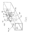
- FIG. 9 shows the interior of a transport container according to the invention 49, in which computer hardware is housed. It is a personal computer (PC).
- the screen 50 is located in the left section, followed (seen from the left) by a tower 51 and a desktop 52 and a printer 53.
- the Desktop 52 is on a raised tablet shelf above printer 53 54 arranged, which stands on the plate for the floor area.
- the tray holder has two handles 55, by which lifting the Tray tray 54 with desktop 52 arranged thereon is facilitated. All devices are surrounded by inflatable air tubes 56 which ensure protection of the devices during transport.
- the hoses 56 are arranged within the transport container 49 such that they can easily be dismantled after deflating, for free access to the devices for their configuration to allow.
- a preferred transport container system 101 according to the invention 10 comprises four system modules, three of which are stacked on top of one another, separated from each other, corresponding to that described above
- Transport container 49 formed transport container according to the invention 102, 103, 104 are of the same type and the fourth one is a transport container coupled frame 105.
- the driving frame 5 comprises a wheel 111 at its four corner areas, 112, 113, which is freely pivotable about a vertical axis.
- the locking device 114 is in a frame 1 of the transport container 102, 103, 104 or housed in the traveling frame 105.
- the locking devices 114 in the respective opposite transverse tube elements 12a, 12b of the transport container 102, 103, 104 or in the lower cross-tube element 12a of the Transport container 102 and the associated frame part 12c of the Moving frame 105 arranged.
- the placement of the locking device 114 in a tubular element 12a, 12b of the frame 1 is realized such that the outer, cuboid dimension of the transport container unchanged remains.
- the locking device 114 does not provide a protruding one Part, creating the risk of injury as well as involuntary Opening of the locking devices 114 excluded is.
- the locking device 114 is in two parts and comprises one of externally operable engaging part 121 and a receiving part 122.
- the engaging part 121 comprises a first insert plate 123, which is to be accommodated in a transverse tube element 12a, 12b.
- the engagement part 121 is completely in the tubular element 12a, 12b (see Fig. 14).
- 11 and 12 corresponds to that along the axis of symmetry 124 taken cross section of the first insert plate 123 of a U-shape, the first insert plate 123 having a wide U-leg 126, the adjacent to the outer wall 125 in the assembled state (see FIG. 1 u. 14) of the corresponding tubular element 12a, 12b, and a shorter one U-leg 127 has.
- the connecting section 128 of the two Leg 126, 127 is diamond-shaped.
- two bores 129 are provided, which with bores (not shown) in the wall 125 lying to the wide U-leg 126 of the tubular element 12a, 12b are aligned (see FIG. 14).
- A is coaxial with the axis of symmetry 124 of the first insert plate 123 Pivot shaft 131 stored in bores 132 and 133, respectively, in the respective U-legs 126, 127 are introduced.
- the swivel shaft 131 includes a thick, cylindrical portion 134, the free one End about the thickness of the assembled part of the engagement part 121 nearby outer wall 125 of the tubular element 12a, 12b extends beyond the U-leg 126.
- In the face of the section 134 is a square recess 135 milled over the using a 4-point key (not shown) on the swivel shaft 131 can be actuated.
- the second thin section 136 of the pivot shaft 131 has a rectangular cross section. In the area of free end of the thin portion 136, the rectangular goes into one circular cross-section, with an annular groove at this transition 137 is provided.
- the swivel limiter 138 is followed by a swivel hook 140 with the same one Recess like the swivel limiter 138.
- the swivel limiter 138 only allows the swivel shaft 131 to be rotated by 90 ° since a nose 139 of the hysteresis-shaped swivel limiter 138 to the Connecting part 128 of the insert plate 123 bumps and further turning of the swivel shaft 131 prevented (see also Fig. 14).
- the swivel hook 140 has a swivel range A from a passive, swiveled position, in the head of the swivel hook 140 is drawn with a solid line is and lies within the first insert plate 123, in a active, swung-out position in which the entire Swivel hook 140 is shown in dashed lines and from the first insert plate 123 protrudes vertically.
- an additional sheet 141 is shown, which is U-shaped in the middle Notch 142 has, which is slightly larger than the diameter of the thick section 134 of the swivel shaft 131 and with one completes the latter adapted semicircular area 143.
- the additional sheet 141 sits in the assembled state between the pivot limiter 138 and the first U-leg 126 with its area 143 on the thick section 134 of the swivel shaft 131.
- the additional plate 141 comprises two Bores 144, which in the assembled state of the additional sheet 141 the above-mentioned holes 129 in the insert plate 123 and with holes in the wall 125 of the tubular element 12a, 12b to align with each other to be attached by rivets.
- the receiving part 122 is shown that the includes second insert plate 146.
- the insert plate 146 has one U-shaped cross-section, with both U-legs 147, 148 in contrast to the first insert plate 121 are of the same length.
- the U-legs 147, 148 are connected by a connecting part 151, the two Has holes 152 through which the second insert plate 146 with the in its assembled state opposite wall of the corresponding Pipe element 12a, 12b is connected by rivets.
- the swivel hook 140 can be of a dashed, passive position in an active, with solid Line drawn position can be pivoted.
- the recesses 163, 164 of the walls 161, 162 see Fig. 14 and 18
- Lock pin 155 pivoted past in its passive position to finally lock with the bolt 154 of the receiving part 122.
- the locking pin 155 is again by the spring 158 returned to its active safety position, creating an independent Removal of the swivel hook 140 excluded from the bolt 154 is.
- the locking pin 155 is first pulled into its passive position. Subsequently, the swivel hook 140 is operated from the outside Swivel shaft 131 back into its passive in the tubular element 12a, 12b retracted position.
- the receiving part 122 is also in one Rohrlement 12a ', 12b' used such that the engaging part 121 and the receiving part 122 when arranging the Transport containers 102, 103, 104 are opposite.
- the contiguous Walls 161, 162 of the tubular elements 12a, 12b (see Fig. 14) and 12a ', 12b' (see Fig. 18) each comprise a recess 63 (see Fig. 14), 64 (see Fig. 18), which are assigned to each other.
- the additional plate 141 fastened to the engagement part 121 projects through the Recess 163 (see Fig. 14) over the tubular element 12a, 12b out into the tubular element 12a ', 12b', causing a lateral displacement the stacked transport containers 102, 103, 104 is prevented.
Landscapes
- Engineering & Computer Science (AREA)
- Mechanical Engineering (AREA)
- Packaging Of Annular Or Rod-Shaped Articles, Wearing Apparel, Cassettes, Or The Like (AREA)
- Pallets (AREA)
Abstract
Description
- Fig.1
- eine perspektivische Ansicht eines die Form des erfindungsgemäßen Transportbehälters bestimmenden Rahmengestells;
- Fig.2
- eine Querschnittsansicht eines für das Rahmengestell verwendeten 4-Kant-Rohres in einer ersten Ausführungsform;
- Fig.3
- eine Querschnittsansicht eines für das Rahmengestell verwendeten 4-Kant-Rohres in einer zweiten Ausführungsform;
- Fig.4
- eine Schnittansicht des unteren Abschnittes des Transportbehälters gemäß der Schnittlinie A-A nach Fig.1;
- Fig.5
- eine Schnittansicht des oberen Abschnittes des Transportbehälters gemäß der Schnittlinie B-B nach Fig.1;
- Fig.6
- den konstruktiven Aufbau einer Platte bzw. einer Tür einer Doppelflügeltür in einer Schnittansicht;
- Fig.7
- eine perspektivische Ansicht des Transportbehälters mit einer angebrachten Doppelflügeltür;
- Fig.8
- eine Schnittansicht des Rahmengestellabschnittes, an dem die Doppelflügeltür angeordnet ist, gemäß der Schnittlinie C-C nach Fig.7;
- Fig.9
- eine Innenansicht des beladenen, transportbereiten Transportbehälters.
- Fig.10
- eine perspektivische Ansicht auf ein erfindungsgemäß angeordnetes Transportbehältersystem;
- Fig.11
- eine Draufsicht eines Elementes - des Eingriffsteils - einer Verriegelungseinrichtung;
- Fig.12
- eine Seitenansicht des Eingriffsteils der Verriegelungseinrichtung nach Fig.3;
- Fig.13
- eine Seitenansicht des Zusatzblechs;
- Fig. 14
- eine perspektivische Ansicht eines Rahmenelements mit dem darin untergebrachten Eingriffsteil der Verriegelungseinrichtung;
- Fig.15
- eine Seitenansicht eines weiteren Elementes - des Aufnahmeteils - einer Verriegelungseinrichtung;
- Fig.16
- das Aufnahmeteil nach Fig.7 in einer Draufsicht;
- Fig.17
- eine Seitendarstellung des Aufnahmeteils und des Verriegelhakens des Eingriffsteils in dessen aktiver und passiver Stellung;
- Fig.18
- eine perspektivische Ansicht eines Rahmenelements mit einem darin untergebrachten Aufnahmeteil einer Verriegelungseinrichtung.
Claims (21)
- Transportbehälter für Transportgüter, insbesondere elektronische Geräte, die frei von jeglicher Schutzverpackung, insbesondere von der herstellerseitigen Verpackung, sind, umfassend:ein quaderförmiges Rahmengestell(1), das einen Bodenbereich (2), Dachbereich (3) und vier Seitenbereichen(4,5,6,7) begrenzt,am Rahmengestell (1) verschwenkbar befestigte Doppelflügeltüren (36), durch die mindestens zwei Seitenbereiche (4,5) des Transportbehälters (49) verschließbar sind,am Rahmengestell (1) befestigte Platten (21,23,28), die den Bodenbereich (2), den Dachbereich (3) und die restlichen Seitenbereiche (6,7) des Transportbehälters (49) bedecken.
- Transportbehälter nach Anspruch 1, dadurch gekennzeichnet, daß die einen der beiden parallelen Seitenbereiche (4,5), vorzugsweise die beiden längeren Seitenbereiche, jeweils von der Doppelflügeltür (36) und die anderen beiden von den Platten (23) verschlossen sind.
- Transportbehälter nach einem der Ansprüche 1 oder 2, dadurch gekennzeichnet, daß das Rahmengestell (1) ein Rohr-System (8) umfaßt.
- Transportbehälter nach Anspruch 3, dadurch gekennzeichnet, daß das durch das Rohr-System (8) gebildete quaderförmige Rahmengestell (1) an seinen Quaderecken Rohr-Steckverbinder (13) mit drei Rohrabgängen (14) für ein Längen-Rohr (11), ein Quer-Rohr (12) und ein Höhen-Rohr (10) aufweist.
- Transportbehälter nach Anspruch 4, dadurch gekennzeichnet, daß der Rohr-Steckverbinder (13) aus Kunststoffgebildet ist und gegebenenfalls einen Stahlkern umfaßt.
- Transportbehälter nach einem der Ansprüche 3 bis 5, dadurch gekennzeichnet, daß die Rohre des Rahmengestells (1) quadratische 4-Kant-Rohre (9) sind.
- Transportbehälter nach Anspruch 6, dadurch gekennzeichnet, daß mindestens ein Auflagesteg (19) senkrecht an jeweils einer der beiden in das Innere des Transportbehälters (49) zumindest teilweise weisenden Seitenflächen (17,18) des 4-Kant-Rohres (9) angeordnet ist.
- Transportbehälter nach Anspruch 7, dadurch gekennzeichnet, daß die Längen- und Quer- 4-Kant-Rohre (11,12)des Behälter-Bodenbereichs (2) sowie jegliche Höhen-4-Kant-Rohre (10) einen Auflagesteg (19) an einer der beiden in das Innere des Transportbehälters (49) zumindest teilweise weisenden Seitenflächen (17,18) des 4-Kant-Rohres (9), sowie die Längen- und Quer- 4-Kant-Rohre (11,12) des Behälter-Dachbereichs (3) jeweils ein Auflagestege(19) an einer in das Innere des Transportbehälters (49) zumindest teilweise weisenden Seitenfläche (17,18) des 4-Kant-Rohres (9) aufweisen.
- Transportbehälter nach einem der Ansprüche 1 bis 8, dadurch gekennzeichnet, daß die Platten (21,23,28) und/oder die Türen (37a,37b) der Doppelflügeltüren (36) gemäß einem Schichtaufbau (31) gebildet sind, der einen Polyäthylen-Kern (32) und eine beidseitige Aluminium-Deckschicht (33) aufweist.
- Transportbehälter nach einem der Ansprüche 1 bis 9, dadurch gekennzeichnet, daß die im Transportbehälter (49) untergebrachten Transportgüter zumindest teilweise von aufblasbaren Luftpolstern (56) umgeben sind.
- Verriegelungseinrichtung zum Koppeln eines Transportbehälters, insbesondere nach einem der Ansprüche 1 bis 9, an ein weiteres Transport-Bauteil, insbesondere einen weiteren Transportbehälter (102, 103, 104), wobei der Transportbehälter ein Rahmengestell (1) aus Rohrelementen (12) aufweist, umfassend:ein Eingriffsteil (121) undein Aufnahmeteil (122),
wobei das Eingriffsteil (121) bzw. das Aufnahmeteil (122) zumindest teilweise im Inneren eines Rohrelementes (12a, 12b) des Transportbehälters (102, 103, 104) montierbar und mit einem in dem zu koppelnden Transport-Bauteil (102, 103, 104, 105) vorgesehenen Aufnahmeteil (122) bzw. Eingriffsteil (121) verriegelbar ist. - Verriegelungseinrichtung nach Anspruch 11, dadurch gekennzeichnet, daß das Eingriffsteil (122) ein Einsatzblech (123) aufweist, das an einer Innenwand des Rohrelementes (12a, 12b) befestigbar ist.
- Verriegelungseinrichtung nach einem der Ansprüche 11 oder 12, dadurch gekennzeichnet, daß an dem Einsatzblech (123) ein Schwenkschaft (131) gelagert ist, an dem ein Schwenkhaken (140) befestigt ist, der von einer passiven in eine aktive Position durch das Betätigen des Schwenkschafts (131) hin und her verschwenkbar ist.
- Verriegelungseinrichtung nach einem der Ansprüche 11 bis 13, dadurch gekennzeichnet, daß das Aufnahmeteil (122) ein Einsatzblech (48) aufweist, das an einer Innenwand des Rohrelementes (12a, 12b) befestigbar ist.
- Verriegelungseinrichtung nach einem der Ansprüche 13 oder 14, dadurch gekennzeichnet, daß der Schwenkhaken (140) des Eingriffsteils (121) in dessen aktiver Position mit einem am Einsatzblech (148) des Aufnahmeteils (122) gelagerten Bolzen (154) in Eingriff kommt.
- Verriegelungseinrichtung nach Anspruch 15, dadurch gekennzeichnet, daß das Aufnahmeteil (122) einen extern betätigbaren Sicherungsstift (155) aufweist, der benachbart zum Bolzen (154) gelagert ist und von einer aktiven Sicherungsstellung, in der ein Hin- und Herverschwenken des Schwenkhakens (140) von dessen aktiver in dessen passive Position blockiert wird, in eine passive Stellung verbringbar ist, in der ein hindernisfreies Hin- und Herverschwenken des Schwenkhakens (140) von dessen passiver Position in dessen aktive Position möglich ist.
- Verriegelungseinrichtung nach Anspruch 16, dadurch gekennzeichnet, daß der Sicherheitsstift (155) des Aufnahmeteils (122) mit einer vorgespannten Feder (158) beaufschlagt ist, die den nicht betätigten Sicherheitsstift (155) in dessen aktiver Stellung hält.
- Verriegelungseinrichtung nach einem der Ansprüche 13 bis 17, dadurch gekennzeichnet, daß der Schwenkschaft (131) des Eingriffsteils (121) mit einem Bewegungsbegrenzer (138) zusammenwirkt, der den Schwenkweg (A) des Schwenkhakens (140) in dessen aktive und passive Position begrenzt.
- Transportsystem aus Transportbehältern, die nach einem der Ansprüche 1 bis 10 gebildet sind, dadurch gekennzeichnet, daß mindestens zwei, vorzugsweise drei Transportbehälter (102, 103, 104) übereinander gestapelt sind, wobei die Transportbehälter (102, 103, 104) an den Längen- oder Quer-Rohre (12) mindestens eine Verriegelungseinrichtung (47, 114) aufweisen.
- Transportbehältersystem nach Anspruch 19 dadurch gekennzeichnet, daß die Verriegelungseinrichtung (114) nach einem der Ansprüche 11 bis 18 gebildet ist.
- Transportbehältersystem nach Anspruch 20 gekennzeichnet durch einen an einem Transportbehälter (102) angeordneten Fahrrahmen (5), in dem ein Eingriffsteil (21) bzw. ein Aufnahmeteil (22) der Verriegelungseinrichtung (14) untergebracht ist.
Applications Claiming Priority (4)
| Application Number | Priority Date | Filing Date | Title |
|---|---|---|---|
| DE19850427 | 1998-10-27 | ||
| DE1998150427 DE19850427A1 (de) | 1998-10-27 | 1998-10-27 | Transportbehälter |
| DE29915800U | 1999-09-08 | ||
| DE29915800U DE29915800U1 (de) | 1998-10-27 | 1999-09-08 | Verriegelungseinrichtung |
Publications (2)
| Publication Number | Publication Date |
|---|---|
| EP0997399A2 true EP0997399A2 (de) | 2000-05-03 |
| EP0997399A3 EP0997399A3 (de) | 2000-08-16 |
Family
ID=26049899
Family Applications (1)
| Application Number | Title | Priority Date | Filing Date |
|---|---|---|---|
| EP99120883A Withdrawn EP0997399A3 (de) | 1998-10-27 | 1999-10-27 | Transportbehälter |
Country Status (1)
| Country | Link |
|---|---|
| EP (1) | EP0997399A3 (de) |
Cited By (4)
| Publication number | Priority date | Publication date | Assignee | Title |
|---|---|---|---|---|
| FR2835241A1 (fr) * | 2002-01-25 | 2003-08-01 | Saxh O | Dispositif de protection et de rangement pour du materiel |
| RU2299393C1 (ru) * | 2006-03-10 | 2007-05-20 | Государственное унитарное предприятие "Конструкторское бюро приборостроения" | Поддон для боевого отделения |
| WO2013056112A1 (en) * | 2011-10-14 | 2013-04-18 | Ergotron, Inc. | Tablet storage and transportation device |
| US8833716B2 (en) | 2011-10-14 | 2014-09-16 | Ergotron, Inc. | Tablet mounting systems and methods |
Family Cites Families (4)
| Publication number | Priority date | Publication date | Assignee | Title |
|---|---|---|---|---|
| ES262616A1 (es) * | 1960-11-19 | 1961-02-01 | Polo Sara | Procedimiento de fabricaciën de cestos partiendo de papel transformado |
| FR2694744B1 (fr) * | 1989-06-16 | 1996-03-29 | Xancho Rene | Palette de manutention, micro stockage, transport sous temperature dirige autonome. |
| DE4414215C2 (de) * | 1994-04-23 | 1996-11-07 | Ohmen Gmbh | Zusammensetzbarer Behälter |
| JPH0870937A (ja) * | 1994-09-10 | 1996-03-19 | Horiba Ltd | 計装品等の収納箱 |
-
1999
- 1999-10-27 EP EP99120883A patent/EP0997399A3/de not_active Withdrawn
Cited By (15)
| Publication number | Priority date | Publication date | Assignee | Title |
|---|---|---|---|---|
| FR2835241A1 (fr) * | 2002-01-25 | 2003-08-01 | Saxh O | Dispositif de protection et de rangement pour du materiel |
| RU2299393C1 (ru) * | 2006-03-10 | 2007-05-20 | Государственное унитарное предприятие "Конструкторское бюро приборостроения" | Поддон для боевого отделения |
| WO2013056112A1 (en) * | 2011-10-14 | 2013-04-18 | Ergotron, Inc. | Tablet storage and transportation device |
| US8833716B2 (en) | 2011-10-14 | 2014-09-16 | Ergotron, Inc. | Tablet mounting systems and methods |
| CN104169829A (zh) * | 2011-10-14 | 2014-11-26 | 爱格升有限公司 | 平板电脑存储和运输装置 |
| US9030828B2 (en) | 2011-10-14 | 2015-05-12 | Ergotron, Inc. | Tablet storage device |
| US9163779B2 (en) | 2011-10-14 | 2015-10-20 | Ergotron, Inc. | Tablet mounting systems, stands, and methods |
| US9182793B2 (en) | 2011-10-14 | 2015-11-10 | Ergotron, Inc. | Tablet storage and transportation device |
| US9207722B2 (en) | 2011-10-14 | 2015-12-08 | Ergotron, Inc. | Tablet and monitor support systems |
| US9298225B2 (en) | 2011-10-14 | 2016-03-29 | Ergotron, Inc. | Tablet storage device |
| US9441782B2 (en) | 2011-10-14 | 2016-09-13 | Ergotron, Inc. | Tablet mounting arm systems and methods |
| US9660466B2 (en) | 2011-10-14 | 2017-05-23 | Ergotron, Inc. | Tablet and monitor support systems |
| CN104169829B (zh) * | 2011-10-14 | 2017-11-17 | 爱格升有限公司 | 平板电脑存储和运输装置 |
| US10044203B2 (en) | 2011-10-14 | 2018-08-07 | Ergotron, Inc. | Tablet storage and transportation device |
| US10476285B2 (en) | 2011-10-14 | 2019-11-12 | Ergotron, Inc. | Tablet storage and transportation device |
Also Published As
| Publication number | Publication date |
|---|---|
| EP0997399A3 (de) | 2000-08-16 |
Similar Documents
| Publication | Publication Date | Title |
|---|---|---|
| DE69015938T2 (de) | Tragbare Anzeigevorrichtung. | |
| DE69308550T2 (de) | Einfaltbarer behälter | |
| WO1995014616A1 (de) | Transport- und lagersystem | |
| DE10297768T5 (de) | Plattenrahmen-/Rahmen-Verbindungsvorrichtung für einen klappbaren Materialtransportbehälter | |
| WO1990015002A1 (de) | Versandverpackung für fahrbereite motorräder und dergleichen | |
| DE69006936T2 (de) | Zusammenlegbarer Behälter für die Lagerung und den Transport von erzeugten Gegenständen. | |
| DE3200216A1 (de) | Zusammenlegbarer und stapelbarer behaelter | |
| EP0997399A2 (de) | Transportbehälter | |
| DE202005016455U1 (de) | Montierbarer Container | |
| EP0186857B1 (de) | Case-Gehäusesystem | |
| EP0401392B1 (de) | Versandverpackung für fahrbereite Motorräder und dergleichen | |
| DE19731868C2 (de) | Mehrweg-Transportbehälter für Zweiradfahrzeuge | |
| DE19850427A1 (de) | Transportbehälter | |
| DE69605761T2 (de) | Mehr- oder Einwegverpackungsbehälter | |
| DE9305904U1 (de) | Zusammenlegbarer Lager- und Transportkasten | |
| DE20008952U1 (de) | Verpackung für elektronische Geräte mit Zubehör | |
| DE102015009085B3 (de) | Verriegelung für Möbelkoffer oder Frachtkontainer | |
| DE4218176A1 (de) | Einrichtung zum transport von gegenstaenden, insbesondere profilen, profilierten staeben oder dergleichen | |
| DE3411381A1 (de) | Als boot nutzbarer anhaenger | |
| DE9113182U1 (de) | Palette | |
| DE9315284U1 (de) | Mehrwegverpackung, insbesondere für empfindliche Geräte | |
| DE9209526U1 (de) | Warenträger | |
| DE8438263U1 (de) | Gehäuse zur Aufnahme eines Rechners mit seinen Bestandteilen | |
| DE102017120200B4 (de) | Traggerüst für einen Planenaufbau eines Nutzfahrzeugs | |
| DE20007124U1 (de) | Verpackungselement mit 3-dimensionaler Abstandsfixierung |
Legal Events
| Date | Code | Title | Description |
|---|---|---|---|
| PUAI | Public reference made under article 153(3) epc to a published international application that has entered the european phase |
Free format text: ORIGINAL CODE: 0009012 |
|
| AK | Designated contracting states |
Kind code of ref document: A2 Designated state(s): AT BE CH CY DE DK ES FI FR GB GR IE IT LI LU MC NL PT SE |
|
| AX | Request for extension of the european patent |
Free format text: AL;LT;LV;MK;RO;SI |
|
| PUAL | Search report despatched |
Free format text: ORIGINAL CODE: 0009013 |
|
| AK | Designated contracting states |
Kind code of ref document: A3 Designated state(s): AT BE CH CY DE DK ES FI FR GB GR IE IT LI LU MC NL PT SE |
|
| AX | Request for extension of the european patent |
Free format text: AL;LT;LV;MK;RO;SI |
|
| AKX | Designation fees paid | ||
| RBV | Designated contracting states (corrected) |
Designated state(s): AT BE CH CY DE DK ES FI FR GB GR IE IT LI LU MC NL PT SE |
|
| 17P | Request for examination filed |
Effective date: 20010215 |
|
| 17Q | First examination report despatched |
Effective date: 20021016 |
|
| STAA | Information on the status of an ep patent application or granted ep patent |
Free format text: STATUS: THE APPLICATION IS DEEMED TO BE WITHDRAWN |
|
| 18D | Application deemed to be withdrawn |
Effective date: 20030501 |