EP0999180A2 - Process for reducing carbon production in solid electrolyte ionic conductor systems - Google Patents
Process for reducing carbon production in solid electrolyte ionic conductor systems Download PDFInfo
- Publication number
- EP0999180A2 EP0999180A2 EP98121852A EP98121852A EP0999180A2 EP 0999180 A2 EP0999180 A2 EP 0999180A2 EP 98121852 A EP98121852 A EP 98121852A EP 98121852 A EP98121852 A EP 98121852A EP 0999180 A2 EP0999180 A2 EP 0999180A2
- Authority
- EP
- European Patent Office
- Prior art keywords
- gas stream
- ion transport
- oxygen
- oxygen ion
- purge
- Prior art date
- Legal status (The legal status is an assumption and is not a legal conclusion. Google has not performed a legal analysis and makes no representation as to the accuracy of the status listed.)
- Withdrawn
Links
Images


Classifications
-
- B—PERFORMING OPERATIONS; TRANSPORTING
- B01—PHYSICAL OR CHEMICAL PROCESSES OR APPARATUS IN GENERAL
- B01D—SEPARATION
- B01D53/00—Separation of gases or vapours; Recovering vapours of volatile solvents from gases; Chemical or biological purification of waste gases, e.g. engine exhaust gases, smoke, fumes, flue gases, aerosols
- B01D53/22—Separation of gases or vapours; Recovering vapours of volatile solvents from gases; Chemical or biological purification of waste gases, e.g. engine exhaust gases, smoke, fumes, flue gases, aerosols by diffusion
-
- B—PERFORMING OPERATIONS; TRANSPORTING
- B01—PHYSICAL OR CHEMICAL PROCESSES OR APPARATUS IN GENERAL
- B01D—SEPARATION
- B01D53/00—Separation of gases or vapours; Recovering vapours of volatile solvents from gases; Chemical or biological purification of waste gases, e.g. engine exhaust gases, smoke, fumes, flue gases, aerosols
- B01D53/32—Separation of gases or vapours; Recovering vapours of volatile solvents from gases; Chemical or biological purification of waste gases, e.g. engine exhaust gases, smoke, fumes, flue gases, aerosols by electrical effects other than those provided for in group B01D61/00
- B01D53/326—Separation of gases or vapours; Recovering vapours of volatile solvents from gases; Chemical or biological purification of waste gases, e.g. engine exhaust gases, smoke, fumes, flue gases, aerosols by electrical effects other than those provided for in group B01D61/00 in electrochemical cells
-
- B—PERFORMING OPERATIONS; TRANSPORTING
- B01—PHYSICAL OR CHEMICAL PROCESSES OR APPARATUS IN GENERAL
- B01D—SEPARATION
- B01D63/00—Apparatus in general for separation processes using semi-permeable membranes
- B01D63/08—Flat membrane modules
- B01D63/087—Single membrane modules
-
- C—CHEMISTRY; METALLURGY
- C01—INORGANIC CHEMISTRY
- C01B—NON-METALLIC ELEMENTS; COMPOUNDS THEREOF; METALLOIDS OR COMPOUNDS THEREOF NOT COVERED BY SUBCLASS C01C
- C01B13/00—Oxygen; Ozone; Oxides or hydroxides in general
- C01B13/02—Preparation of oxygen
- C01B13/0229—Purification or separation processes
- C01B13/0248—Physical processing only
- C01B13/0251—Physical processing only by making use of membranes
-
- C—CHEMISTRY; METALLURGY
- C01—INORGANIC CHEMISTRY
- C01B—NON-METALLIC ELEMENTS; COMPOUNDS THEREOF; METALLOIDS OR COMPOUNDS THEREOF NOT COVERED BY SUBCLASS C01C
- C01B3/00—Hydrogen; Gaseous mixtures containing hydrogen; Separation of hydrogen from mixtures containing it; Purification of hydrogen; Reversible storage of hydrogen
- C01B3/02—Production of hydrogen; Production of gaseous mixtures containing hydrogen
- C01B3/32—Production of hydrogen; Production of gaseous mixtures containing hydrogen by reaction of gaseous or liquid organic compounds with gasifying agents, e.g. water, carbon dioxide or air
- C01B3/34—Production of hydrogen; Production of gaseous mixtures containing hydrogen by reaction of gaseous or liquid organic compounds with gasifying agents, e.g. water, carbon dioxide or air by reaction of hydrocarbons with gasifying agents
- C01B3/36—Production of hydrogen; Production of gaseous mixtures containing hydrogen by reaction of gaseous or liquid organic compounds with gasifying agents, e.g. water, carbon dioxide or air by reaction of hydrocarbons with gasifying agents using oxygen; using mixtures containing oxygen as gasifying agents
-
- B—PERFORMING OPERATIONS; TRANSPORTING
- B01—PHYSICAL OR CHEMICAL PROCESSES OR APPARATUS IN GENERAL
- B01D—SEPARATION
- B01D2313/00—Details relating to membrane modules or apparatus
- B01D2313/10—Specific supply elements
-
- B—PERFORMING OPERATIONS; TRANSPORTING
- B01—PHYSICAL OR CHEMICAL PROCESSES OR APPARATUS IN GENERAL
- B01D—SEPARATION
- B01D2313/00—Details relating to membrane modules or apparatus
- B01D2313/22—Cooling or heating elements
- B01D2313/221—Heat exchangers
-
- B—PERFORMING OPERATIONS; TRANSPORTING
- B01—PHYSICAL OR CHEMICAL PROCESSES OR APPARATUS IN GENERAL
- B01D—SEPARATION
- B01D2313/00—Details relating to membrane modules or apparatus
- B01D2313/42—Catalysts within the flow path
-
- C—CHEMISTRY; METALLURGY
- C01—INORGANIC CHEMISTRY
- C01B—NON-METALLIC ELEMENTS; COMPOUNDS THEREOF; METALLOIDS OR COMPOUNDS THEREOF NOT COVERED BY SUBCLASS C01C
- C01B2210/00—Purification or separation of specific gases
- C01B2210/0043—Impurity removed
- C01B2210/0046—Nitrogen
Definitions
- the invention relates to an apparatus and process for improving the operation efficiency of solid electrolyte ionic conductor systems and, more particularly, to an apparatus and process for reducing the production and deposition of carbon and/or coke on the permeate side of the oxygen ion transport membrane when a carbon-containing reactive gas stream is used as a purge by employing an exhaust gas recirculation process.
- Solid electrolyte ionic conductor materials that transport oxygen ions appear to be very useful for the separation of oxygen from gas mixtures, for example, air.
- Certain of these oxygen ion transport materials are mixed conductors, that is, they conduct both oxygen ions and electrons.
- oxygen ion transport materials contain mobile oxygen ion vacancies that provide conduction sites for selective transport of oxygen ions through the material.
- the ion transport is driven by the ratio of partial pressures of oxygen across the membrane: oxygen ions flow from the side with high oxygen partial pressure to the side that has a low oxygen partial pressure. Ionization of oxygen to oxygen ions takes place on the "cathode-side" of the membrane and these oxygen ions are transported across the oxygen ion transport membrane.
- oxygen ions deionize on the "anode-side" and are released as oxygen molecules.
- external electrodes are placed on the surfaces of the electrolyte and the electronic current is carried in an external circuit in an electrically-driven mode.
- electrons are transported to the cathode internally in mixed conducting materials in a pressure-driven mode, thus completing the circuit and obviating the need for external electrodes.
- Mixed conductors can also be used in electrically-driven mode, although it is desirable to do so only when the electronic conductivity is limiting.
- oxygen ion transport materials have several potential uses in the area of air separation and purification of gases.
- Some applications of these oxygen ion transport membranes involve the use of an anode side reactive purge to improve ion transport-based processes for purification of oxygen-containing gases and for syngas, hydrogen and carbon monoxide production.
- the basic motivation behind using such a reactive purge is to reduce the oxygen partial pressure on the anode side of the oxygen ion transport membrane greatly by introducing an oxygen scavenging gas (for example, methane, methanol, ethanol, or hydrogen) for purification/separation operations. This reduction in the oxygen partial pressure enhances the pressure-driven oxygen transport through the oxygen ion transport membrane.
- an oxygen scavenging gas for example, methane, methanol, ethanol, or hydrogen
- an oxygen ion transport membrane can take advantage of the low partial oxygen pressure generated on the anode by an oxygen consuming reaction, such as partial oxidation, to transport oxygen from a relatively low total pressure air stream to a high total pressure reaction site. This avoids a separate air separation plant and expensive compression system.
- a second difficulty is that all the fuel is introduced at one end of the oxygen ion transport module in a reactive purge process, while the oxygen is incrementally transported through the oxygen ion transport membrane along its entire length.
- the anode side gas composition is always fuel-rich near the fuel inlet and becomes increasingly fuel-lean as one approaches the other end of the oxygen ion transport module. This occurs irrespective of the overall fuel-to-oxygen ratio used in the oxygen ion transport module.
- Highly fuel rich operation at the purge inlet end leads to very low gas phase oxygen activity which could lead to corrosion or chemical decomposition of the membrane material.
- Another problem is that high overall fuel-to-oxygen ratios in the oxygen ion transport module will lead to incomplete combustion of the fuel, and cause the outgoing gas to contain species such as hydrogen, carbon monoxide and unreacted fuel which will adversely affect the fuel efficiency.
- a highly reactive gas such as hydrogen may be beneficial for effectively scavenging oxygen from the purge side of the oxygen transport membrane.
- hydrogen gas is generally more reactive than most organic fuels, its high cost and scarce availability make its use less desirable than carbon-containing fuels (for example, natural gas).
- a tubular solid-state membrane module is disclosed in Dyer et al., U.S. Patent No. 5,599,383, having a plurality of tubular membrane units, each unit having a channel-free porous support and a dense mixed conducting oxide layer supported thereon.
- the porous support of each unit is in flow communication with one or more manifolds or conduits to discharge oxygen which has permeated through the dense layer and the porous support.
- Another object of the invention is to reduce the amount of heat generated in the oxygen ion transport module which leads to undesirable exotherms in the oxygen ion transport module and may damage its components.
- Yet another object of the invention is to introduce fuel gas in such a way as to minimize the concentration gradient along the oxygen ion transport membrane from the fuel inlet to the feed end of the oxygen ion transport module.
- the invention comprises a process for inhibiting the formation of carbon and/or coke from a carbon-containing reactive gas stream on the permeate side of an oxygen ion transport membrane and for increasing the equilibrium oxygen activity in the purge gas so as to improve the chemical stability of the oxygen ion transport membrane in the presence of the reactive gas.
- a feed gas stream containing elemental oxygen and at least one other gas is separated using an oxygen ion transport module having an oxygen ion transport membrane with a retentate side and a permeate side such that an oxygen-depleted gas stream forms on the retentate side and a gas stream containing reaction products forms on the permeate side.
- the permeate side of the oxygen ion transport membrane is purged with the carbon-containing reactive gas stream and at least a portion of the exhaust gas stream formed from the reaction of the reactive gas stream with the oxygen gas stream permeating through the oxygen ion transport membrane is recirculated to purge the permeate side of the oxygen ion transport membrane, thereby inhibiting the formation of carbon and/or coke on that side.
- Exhaust gas recirculation according to the present invention also introduces oxygenated species (for example, carbon dioxide, carbon monoxide, water vapor) into the purge gas which results in significantly increased equilibrium oxygen activity in the purge gas, especially near the purge inlet.
- At least a portion of the exhaust gas stream is passed through a separator to remove carbon dioxide and at least a portion of the said carbon dioxide is combined with a recirculating portion of the non-separated exhaust gas stream before it is used to purge the permeate side of the oxygen ion transport membrane.
- the recirculating portion of the carbon dioxide stream from the separator may be used solely, and without contribution from the non-separated exhaust gas stream, to form the recirculating gas stream used to purge the permeate side of the oxygen ion transport membrane.
- the exhaust gas stream exits the oxygen ion transport module before it is recirculated and/or separated.
- the feed gas stream is air.
- water vapor or steam is added to at least a portion of the recirculated exhaust gas stream before it is used to purge the permeate side of the oxygen ion transport membrane. If water vapor or steam is added to the recirculated exhaust gas stream, another preferred embodiment uses a reformer unit that allows the water vapor and unreacted carbon-containing fuel to form carbon monoxide and hydrogen gas before the reformed gas stream is used to purge the permeate side of the oxygen ion transport membrane.
- the retentate gas stream is recovered as a nitrogen product.
- the exhaust gas recirculation is operated to increase the oxygen partial pressure on the permeate side to a desired operating range and/or to maintain the oxygen ion transport module within a preferred range of operating temperatures by mitigating undesirable reaction exotherms.
- one or more of the components of the exhaust gas stream are separated from the exhaust gas stream prior to recirculation.
- the invention involves a configuration allowing the recirculation of a portion of the exhaust gases produced in a reactively purged oxygen ion transport module that employs an oxygen ion transport membrane to separate oxygen from an oxygen-containing gas.
- This exhaust gas recirculation (EGR) process may mitigate or eliminate many of the potential problems associated with a reactively purged oxygen ion transport module which include sharp exotherms, carbon/coke formation, very low oxygen activity on the purge side (particularly at the purge inlet end) leading to chemical/mechanical instability of the membrane, and low oxygen flux due to slow fuel combustion on the purge side.
- EGR can also mitigate flow maldistribution problems on the purge side of the oxygen ion transport membrane by increasing the purge side gas flowrate.
- Multicomponent oxide compositions that exhibit oxygen ion conduction have been developed in the recent years. Such oxygen ion transport materials are potentially useful for separating oxygen from oxygen containing gas streams.
- the behavior of oxygen ion transport membranes has been extensively studied (for example, for fuel cells).
- Reactive purge arrangements are disclosed in Reactive Purge for Solid Electrolyte Membrane Gas Separation , U.S. Patent No. 5,837,125 and incorporated herein by reference.
- Preferred configurations for ion transport modules utilizing a reactive purge are disclosed in Solid Electrolyte Ionic Conductor Reactor Design , U.S. Patent No. 5,820,655 and also incorporated herein by reference. Both patents are commonly owned with the present application.
- Fig. 1 schematically depicts the configuration for employing EGR in a reactively purged oxygen ion transport process.
- the invention relates to the recirculation of a portion of the exhaust purge gas stream to the purge inlet to suppress carbon and/or coke formation and improve the performance of the oxygen ion transport module.
- oxygen-containing feed gas stream 1 is compressed in blower or compressor 2 and then warmed against the waste or product streams 10 and 15 in heat exchanger 26 .
- the warmed feed gas stream 4 is then optionally heated in heater 5 .
- the hot feed gas stream 6 then enters the feed side of oxygen ion transport module 7 including an oxygen ion transport membrane 8 , having retentate side 8a and permeate side 8b .
- the retentate gas stream 9 is divided into two portions: hot retentate gas stream 10 which may be a waste or a product gas stream and is used in heat exchanger 3 , as mentioned above, and as a part of the retentate purge gas stream 12 .
- Exhaust gas stream 13 exits from the oxygen ion transport module 7 and is divided into two portions: exhaust gas stream 15 and recycle exhaust gas stream 14 .
- Gas stream 15 is used in heat exchanger 3 , as mentioned above, to produce gas stream 16 which is discarded as waste (for example, in purification) or is recovered as a product (for example, in syngas production), depending on the application desired.
- Exhaust gas stream 14 is optionally cooled using heat rejection unit 17 to form exhaust gas stream 18 .
- the heat rejection unit 17 may involve, for example, a process by which the exhaust gas stream 11 is cooled by water, by adding atomized water to the exhaust gas stream 11 , or by bubbling through water.
- Exhaust gas stream 18 is optionally compressed by optional compressor 25 , preferably located downstream from heat rejection unit 17 in the EGR circuit, to make higher-pressure gas stream 19 .
- Gas stream 19 is combined with retentate purge gas stream 12 obtained from the retentate gas stream 9 and reactive gas stream 20 to form purge gas stream 21 which is optionally heated using heater 22 to form purge gas stream 23 .
- Purge gas stream 23 is used to purge the permeate side 8b of oxygen ion transport membrane 8 .
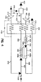
- Fig. 2 illustrates a modification of the configuration shown in Fig. 1.
- oxygen-containing feed gas stream 41 is compressed in blower or compressor 42 and then warmed against the waste or product streams 50 and 55 in heat exchanger 43 .
- the warmed feed gas stream 44 is then optionally heated in heater 45 .
- the hot feed gas stream 46 then enters the feed side of oxygen ion transport module 47 including an oxygen ion transport membrane 48 , having retentate side 48a and permeate side 48b .
- the retentate gas stream 49 is divided into two portions: hot retentate gas stream 50 which may be a waste or a product gas stream and is used in heat exchanger 43 , to produce gas stream 51 , and retentate purge gas stream 52 .
- Exhaust gas stream 53 exits from the oxygen ion transport module 47 and is divided into two portions: exhaust gas stream 55 and recycle exhaust gas stream 54 .
- Gas stream 55 is used in heat exchanger 43 , as mentioned above, to produce gas stream 56 which is discarded as waste (for example, in purification) or is recovered as a product (for example, in syngas production), depending on the application desired.
- Exhaust gas stream 54 is itself divided into a first gas stream portion 57 and a second gas stream portion 61 .
- the first gas stream portion 57 is passed through saturator 58 where a small amount of steam is added to produce saturated gas stream 59 which is combined with the second gas stream portion 61 to form gas stream 62 .
- Another source of steam or an atomizer can also be used instead of saturator 58 to introduce steam into the exhaust gas stream 54 .
- Oxygen-containing gas stream 77 containing a small amount of air and/or steam is optionally added to gas stream 59 .
- Gas stream 62 is then passed through partial oxidation/reformer unit 63 (optionally catalytic), where the unreacted organic fuel in gas stream 62 forms carbon monoxide and hydrogen gas and exits as gas stream 64 .
- a partial oxidation/reformer reactor unit is one in which a hydrocarbon reacts with steam or oxygen to produce carbon monoxide and hydrogen gas.
- the exhaust gas stream 64 may be optionally cooled by heat rejection unit 65 to form exhaust gas stream 66 .
- the heat rejection unit 65 may involve, for example, a process by which the exhaust gas stream 64 is cooled by water, by adding atomized water to the exhaust gas stream 64 , or by bubbling through water.
- Exhaust gas stream 66 is combined with retentate purge gas stream 52 obtained from the retentate gas stream 49 and reactive gas stream 60 to form purge gas stream 67 which is optionally heated using heater 68 to form purge gas stream 69 .
- Purge gas stream 69 is used to purge the permeate side 48b of the oxygen ion transport membrane 48 .
- gas stream 60 may be optionally heated using heater 68 before mixing with gas streams 52 and 66 .
- a pressure drop on the permeate side 48b of oxygen ion transport membrane 48 would cause exhaust gas stream 54 , and consequently gas stream 66 , to be at a lower pressure than gas streams 52 and 60 , and recirculation of the exhaust gases would require recompression.
- the temperature of exhaust gas stream 54 is relatively high (typically 450°C to 1100°C) because of the high temperature of operation of the oxygen ion transport process and because of the heat generated by the exothermic reaction on the permeate side 48b of the oxygen ion transport membrane 48 .
- Fig. 3 shows a method for circumventing these potential problems of Fig. 2 by using Venturi eductor 108 .
- feed gas stream 81 is compressed in blower or compressor 82 and then warmed against the waste or product streams 90 and 95 in heat exchanger 83 .
- the warmed feed gas stream 84 is then optionally heated in heater 85 .
- the hot feed gas stream 86 then enters the feed side of oxygen ion transport module 87 including an oxygen ion transport membrane 88 , having retentate side 88a and permeate side 88b .
- the retentate gas stream 89 is divided into two portions: hot retentate gas stream 90 which may be a waste or a product gas stream and is used in heat exchanger 83 , to produce gas stream 91 , and retentate purge gas stream 92 .
- Exhaust gas stream 93 exits from the oxygen ion transport module 87 and is divided into two portions: exhaust gas stream 95 and recycled exhaust gas stream 94 .
- Exhaust gas stream 95 is used in heat exchanger 83 , as mentioned above, to produce gas stream 96 which is discarded as waste (for example, in purification) or is recovered as a product (for example, in syngas production), depending on the application desired.
- Exhaust gas stream 94 is itself divided into a first gas stream portion 97 and a second gas stream portion 101 .
- the first gas stream portion 97 is passed through saturator 98 where a small amount of steam is added to produce saturated gas stream 99 which is combined with the second gas stream portion 101 to form gas stream 102 .
- Another source of steam or an atomizer can also be used instead of saturator 98 to introduce steam into the exhaust gas stream 94 .
- Gas stream 112 containing a small amount of air and/or steam is optionally added to gas stream 99 .
- Gas stream 102 is then passed through partial oxidation/reformer reactor unit 103 (optionally catalytic), where the unreacted organic fuel in gas stream 102 reacts with steam or oxygen to form carbon monoxide and hydrogen gas and exits as gas stream 104 .
- the exhaust gas stream 104 may be optionally cooled by heat rejection unit 105 to form exhaust gas stream 106 .
- the heat rejection unit 105 may involve, for example, a process by which the exhaust gas stream 104 is cooled by water, by adding atomized water to the exhaust gas stream 104 , or by bubbling through water.
- the pressure of stream 106 optionally is increased by a compressor 113 , shown in phantom, to produce stream 114 .
- Retentate purge gas stream 92 obtained from the retentate gas stream 89 and high pressure reactive gas stream 100 are combined to form gas stream 107 .
- Gas stream 107 is a high pressure driver gas stream and is passed through a Venturi nozzle to create a low static pressure region at the throat of the Venturi eductor 108 .
- the exhaust gas stream to be recirculated is introduced into the low pressure region at the throat of Venturi eductor 108 .
- Venturi eductors are simple devices as they have no moving parts, and are inexpensive and rugged as compared to traditional compression equipment.
- Venturi eductors can recirculate the hot exhaust gas stream, thus eliminating the need for cooling heat transfer equipment.
- optional heat rejection units 17 , 65 , and 105 in Figs. 1, 2 and 3, respectively, are eliminated in some constructions.
- the hot recirculated exhaust gas can also be used to beneficially preheat the inlet purge gas stream.
- Venturi eductor Using the Venturi eductor, exhaust gas stream 106 is thereby combined with gas stream 107 to form gas stream 109 which is optionally heated using heater 110 to form purge gas stream 111 . Purge gas stream 111 is then used to purge the permeate side 88b of the oxygen ion transport membrane 88 .
- a similar variation using a Venturi eductor can be adapted for the embodiment of Fig. 1.
- a part of the purge side combustion products can also be recirculated and mixed with purge gas streams 23 , 69 , and 111 internally and still achieve the benefits outlined above.
- natural or forced convection can be effected on the purge side to induce mixing.
- the incoming purge gas streams 23 , 69 , and 111 can be brought in at high pressure/velocity to form swirling jets and thus bring about mixing of the combustion products.
- Fig. 4 shows an embodiment of the invention in which carbon dioxide is separated from the exhaust gas stream and recirculated to inhibit the formation of carbon on the anode side of the oxygen ion transport module.
- Air 401 is compressed in compressor 402 to a moderate pressure, heated in heat exchanger 440 , recovering heat from retentate stream 409 and product stream 422 , and is optionally further heated by heater 405 .
- Air, then as stream 406 enters the cathode side 408a of oxygen ion transport module 407 .
- a portion or most of the oxygen contained in the air stream is permeated to the anode side 408b of oxygen ion transport module 407 by pressure driven ion transport and reacts with the fuel fed to the anode side with feed stream 421 in a partial or complete oxidation reaction.
- the retentate stream 409 exiting the oxygen ion transport module 407 is discharged from the system after recovery of contained heat in heat exchanger 440 either as a waste stream 410 or as nitrogen product.
- the permeate stream 422 containing reaction products such as carbon monoxide, hydrogen, carbon dioxide, steam and some unreacted fuel, exits the anode side 408b of oxygen ion transport module 407 , is cooled in exchanger 440 and then flows to a separator 412 , in which at least a portion of one or more of the reaction products, such as carbon dioxide, are removed from exhaust stream 411 .
- separator 411 may be a polymeric membrane separator, a hot carbonate wash system, an ethanolamine absorption system or another suitable CO 2 removal system as would be apparent to those of skill in the art.
- At least a portion of the exhaust stream 411 bypasses separator 412 via bypass stream 423 and is added to the separated carbon dioxide stream for recirculation.
- this has the advantage of adding some hydrogen at the entrance of the oxygen ion transport module, which increases the reactivity of feed stream 421 in the oxygen ion transport module 407 .
- At least a portion of the separated carbon dioxide, and optionally bypass stream 423 is recompressed in compressor 416 , optionally heated in exchanger 440 , mixed with fuel stream 420 , and optionally steam, and introduced to the anode side 408b of oxygen ion transport reactor 407 as a purge gas stream.
- a suitable catalyst 450 such as nickel on alumina supports, may be added into the permeate passage of oxygen ion transport module 407 .
- oxygen ion transport materials are unstable under very highly reducing conditions (for example, when the oxygen partial pressure is less than 10 -16 atm).
- Certain embodiment of the invention by introducing oxygen containing compounds such as water, carbon monoxide, and carbon dioxide in the purge stream, increase the equilibrium oxygen activity on the purge side of the oxygen ion transport membrane (especially near the inlet) to a desired operating range, thus preventing degradation of the oxygen ion transport membrane.
- the exhaust gas stream is cooled outside the oxygen ion transport module, thus simplifying the heat rejection process.
- passing a portion of the exhaust gas recirculation stream through a saturator will cool the exhaust gas stream to some extent, thus providing control over the temperature of the stream entering the reformer unit.
- the saturator is any device where a portion of the thermal energy in the exhaust gas recirculation stream is used to vaporize water.
- the temperature of the purge gas stream can be controlled by adjusting the relative amounts of the recirculated exhaust gas stream and the retentate gas stream, thus giving a positive means for temperature control in the oxygen ion transport module.
- the purge gas stream exit temperature from a reactively purged process will be higher than the purge gas stream inlet temperature. In such cases, the exhaust gas recirculation process would reduce the heating requirements for the purge gas stream, which in turn could reduce or eliminate heat exchanger requirements for the purge gas stream.
- the exhaust gas stream can be cooled by bubbling the exhaust gases through water to form steam and this steam, or a portion thereof, can be returned to the oxygen ion transport module to mix with the purge gas stream.
- Addition of steam to the purge gases will enhance reforming (which is endothermic) of the reactive gas stream which decreases the undesirable exotherms in the oxygen ion transport module.
- the presence of water vapor in the purge gas stream will facilitate combustion of the reactive gas stream and the addition of steam to the purge gas stream will also reduce the retentate gas purge requirement.
- the exhaust gas stream will contain combustible species such as hydrogen gas, carbon monoxide, and hydrocarbons.
- the exhaust gas recirculation process provides a way to recycle some of the combustibles and thereby improve the overall fuel efficiency.
- EGR will result in hydrogen gas being introduced with the purge gas stream.
- hydrogen gas is much more reactive than most other gaseous fuels and will consume oxygen on the purge side of the oxygen ion transport membrane; hydrogen gas diffuses faster than most gases, and will reach the oxygen ion transport membrane surface and scavenge oxygen permeating through the oxygen ion transport membrane more effectively, thereby improving the oxygen flux to the purge side; and hydrogen gas combustion will generate heat locally, which will aid the oxidation of the organic fuel species.
- hydrogen itself could be used as the purge gas, it may be uneconomical to do so.
- the present invention may generate hydrogen gas from the unreacted reactive gas stream, thereby minimizing fuel waste, and also offers other benefits of using hydrogen outlined above.
- the EGR process also reduces the need for external diluent in the purge inlet stream and this is particularly valuable in instances where the only other diluent stream available is the product gas stream.
- the schemes discussed here will find applications in most reactively purged oxygen ion transport systems, for example, oxygen ion transport-based deoxo for gas purification applications.
- oxygen ion transport-based syngas/CO/H 2 production with EGR will be benefited by catalytic reforming of the unreacted fuel taking place outside the oxygen ion transport module, the presence of hydrogen and carbon monoxide in the purge stream that assists the purge side reactions, and the heat rejection outside the oxygen ion transport module.
- methane is used as the fuel.
- Any gas phase carbonaceous fuel may be used in the oxygen ion transport module.
- Example 1 Effect of the equivalence ratio ⁇ on the equilibrium gas composition (mole fractions) in a methane-oxygen mixture at 1000°C and 1 atm is shown in Table I.
- the oxygen ion transport module will operate under fuel rich conditions: thus at typical values of the overall equivalence ratio ⁇ (for example, ⁇ greater than 1), carbon monoxide and hydrogen will be formed at chemical equilibrium. By recirculating a part of the exhaust, these fast combusting components can be added to the purge side, thereby enhancing oxygen ion transport performance. It also shows that at high values of ⁇ (for example, ⁇ greater than 4), carbon formation would occur in a reactively purged oxygen ion transport module.
- ⁇ for example, ⁇ greater than 1
- Example 2 For a fixed ratio ⁇ , the effect of the recirculation ratio ⁇ on carbon formation is shown in Table II.
- Table II illustrates that even at the small recirculation ratio ⁇ of 0.2, carbon formation in the oxygen ion transport module can be substantially eliminated. It should be noted that if chemical equilibrium is not reached, the oxygen partial pressure of the purge stream may be substantially lower than 10 -16 atm. From Table II, it can be seen that the mole fraction of hydrogen gas in the purge out gas streams 14 and 16 decreases as the recirculation ratio increases. At the same time, however, the fraction of hydrogen gas added to purge in gas stream 14 increases. As discussed above, this will be beneficial to operation of the oxygen ion transport module. For example, in an oxygen ion transport deoxo gas purification unit with a countercurrent flow configuration, purge inlet and product are the same end of the oxygen ion transport module. The outgoing product will typically have a very small amount of oxygen. The presence of hydrogen gas in gas stream 14 will ensure efficient fuel oxidation near the purge inlet, thereby creating the necessary driving force for oxygen transport across the membrane and help achieve the desired purification of the product.
- EGR results in greatly increased oxygen partial pressure in the purge stream.
- Typical ranges for operating parameters of the oxygen ion transport module are as follows:
- solid electrolyte ionic conductor As mentioned above, the term “solid electrolyte ionic conductor”, “solid electrolyte”, “ion conductor”, “oxygen ion transport membrane” or “ion transport membrane” is generally used herein to designate either an ionic-type (electrically-driven) or a mixed conductor-type (pressure-driven) system or material capable of oxygen-ion transport, unless otherwise specified.
- nitrogen will usually mean oxygen-depleted gas, that is, oxygen-depleted relative to the feed gas.
- oxygen ion transport membrane only allows oxygen ion transport. Therefore, the composition of the retentate will depend on the composition of the feed gas.
- the feed gas will be depleted of oxygen but will retain nitrogen and any other gases (for example, argon) present in the feed gas.
- nitrogen for example, argon
- elemental oxygen means any oxygen that is uncombined with any other element in the Periodic Table. While typically in diatomic form, elemental oxygen includes single oxygen atoms, triatomic ozone, and other forms uncombined with other elements.
- carbon-containing reactive gas stream means a gas stream that may include hydrocarbons (for example, methane), other combustible organic compounds (for example, methanol, ethanol), carbon monoxide, and powdered carbon (that is, coke).
- hydrocarbons for example, methane
- other combustible organic compounds for example, methanol, ethanol
- carbon monoxide for example, methanol, ethanol
- powdered carbon that is, coke
- high purity refers to a product stream which contains less than five percent by volume of undesired gases.
- the product is at least 98.0% pure, more preferably 99.9% pure, and most preferably at least 99.99% pure, where "pure" indicates an absence of undesired gases.
Landscapes
- Chemical & Material Sciences (AREA)
- Chemical Kinetics & Catalysis (AREA)
- Organic Chemistry (AREA)
- Engineering & Computer Science (AREA)
- Analytical Chemistry (AREA)
- General Chemical & Material Sciences (AREA)
- Oil, Petroleum & Natural Gas (AREA)
- Inorganic Chemistry (AREA)
- General Health & Medical Sciences (AREA)
- Combustion & Propulsion (AREA)
- Health & Medical Sciences (AREA)
- Electrochemistry (AREA)
- Separation Using Semi-Permeable Membranes (AREA)
- Hydrogen, Water And Hydrids (AREA)
- Fuel Cell (AREA)
- Physical Or Chemical Processes And Apparatus (AREA)
Abstract
Description
| Equilibrium composition of the purge out gas in an oxygen ion transport module without EGR. | |||||||
| | H2(g) | CO(g) | H2O(g) | CO2(g) | Carbon (s) | CH4(g) | p02(atm) |
| 1 | 0 | 0 | 0.67 | 0.33 | 0 | 0 | 1.0E-06 |
| 1.1 | 0.07 | 0.05 | 0.6 | 0.28 | 0 | 0 | 2.2E-13 |
| 2 | 0.42 | 0.24 | 0.24 | 0.09 | 0 | 0 | 9.9E-16 |
| 3 | 0.58 | 0.31 | 0.08 | 0.03 | 0 | 0 | 6.1E-17 |
| 4 | 0.66 | 0.33 | 0 | 0 | 0 | 0 | 5.4E-20 |
| 4.1 | 0.66 | 0.32 | 0 | 0 | 0.01 | 0 | 4.5E-20 |
| 5 | 0.66 | 0.27 | 0 | 0 | 0.07 | 0 | 3.4E-20 |
| Equilibrium composition of the purge out gas streams 14/16 in an oxygen ion transport module with EGR. (Note: ξ = 0 corresponds to a case without EGR.) | |||||||
| ξ | H2(g) | CO(g) | H2O(g) | CO2(g) | Carbon (s) | CH4(g) | p02(atm) |
| 0 | 0.66 | 0.27 | 0 | 0 | 0.07 | 0 | 3.4E-20 |
| 0.2 | 0.66 | 0.33 | 0 | 0 | 0 | 0 | 7.6E-20 |
| 0.41 | 0.63 | 0.32 | 0.03 | 0.01 | 0 | 0 | 8.3E-18 |
| 0.49 | 0.62 | 0.32 | 0.04 | 0.01 | 0 | 0 | 1.5E-17 |
| 0.61 | 0.61 | 0.32 | 0.06 | 0.02 | 0 | 0 | 2.5E-17 |
| 0.69 | 0.6 | 0.31 | 0.06 | 0.02 | 0 | 0 | 3.2E-17 |
| 0.82 | 0.59 | 0.31 | 0.07 | 0.02 | 0 | 0 | 4.4E-17 |
| 1.5 | 0.56 | 0.3 | 0.1 | 0.04 | 0 | 0 | 1.0E-16 |
| 2.03 | 0.55 | 0.29 | 0.12 | 0.04 | 0 | 0 | 1.4E-16 |
| 3 | 0.53 | 0.29 | 0.13 | 0.05 | 0 | 0 | 1.9E-16 |
| 4 | 0.52 | 0.28 | 0.14 | 0.05 | 0 | 0 | 2.2E-16 |
| 5.25 | 0.52 | 0.28 | 0.15 | 0.05 | 0 | 0 | 2.5E-16 |
| 9 | 0.51 | 0.28 | 0.16 | 0.06 | 0 | 0 | 3.0E-16 |
| 11.5 | 0.5 | 0.28 | 0.16 | 0.06 | 0 | 0 | 3.1E-16 |
Claims (20)
- A process for inhibiting the formation of carbon and/or coke from a carbon-containing reactive gas stream on the permeate side of an oxygen ion transport membrane, the process comprising:separating a feed gas stream containing elemental oxygen and at least one other gas using an oxygen ion transport module having the oxygen ion transport membrane with a retentate side and a permeate side such that an oxygen-depleted gas stream forms on the retentate side and a gas stream containing oxygen reaction products forms on the permeate side;purging the permeate side of the oxygen ion transport membrane with the carbon-containing reactive gas stream; andrecirculating at least a portion of an exhaust gas stream formed from the reaction of the reactive gas stream with the oxygen gas stream permeating through the oxygen ion transport membrane to purge the permeate side of the oxygen ion transport membrane, thereby inhibiting the formation of carbon and/or coke thereon.
- The process according to claim 1, wherein the exhaust gas stream exits the oxygen ion transport module before it is recirculated.
- The process according to claim 1, wherein water vapor or an oxygen-containing gas stream is added to at least a portion of the recirculated exhaust gas stream before it is used to purge the permeate side of the oxygen ion transport membrane.
- The process according to claim 3, wherein the water vapor is added when at least a portion of the recirculated exhaust gas stream is passed through a saturator to add steam.
- The process according to claim 3, wherein the recirculated exhaust gas stream containing water vapor or an oxygen-containing gas stream is passed through a reactor unit in which the unreacted carbon-containing fuel forms carbon monoxide and hydrogen gas before the reformed gas stream is used to purge the permeate side of the oxygen ion transport membrane.
- The process according to claim 5, wherein the reactor unit is a catalytic unit.
- The process according to claim 5, wherein the reformed gas stream is passed through a Venturi eductor driven by a driver gas stream before it is used to purge the permeate side of the oxygen ion transport membrane.
- The process according to claim 5, wherein the reformed gas stream is cooled and/or compressed before it is used to purge the permeate side of the oxygen ion transport membrane.
- The process according to claim 1, wherein the carbon-containing reactive gas stream comprises a hydrocarbon.
- The process according to claim 9, wherein the hydrocarbon is methane.
- The process according to claim 9, wherein the gas stream is heated before it is used to purge the permeate side of the oxygen ion transport membrane.
- The process according to claim 1, wherein the feed gas stream is air.
- The process according to claim 12, wherein the oxygen-depleted gas stream is recovered as a nitrogen gas product stream.
- The process according to claim 1, wherein the exhaust gas stream is cooled before it is recirculated to purge the permeate side of the oxygen ion transport membrane.
- The process according to claim 1, wherein the temperature of the purge gas stream is controlled by adjusting the relative amounts of the exhaust gas stream and the retentate gas stream used to purge the permeate side of the oxygen ion transport membrane.
- A process for increasing the oxygen partial pressure on the permeate side of an oxygen ion transport membrane, the process comprising:separating a feed gas stream containing elemental oxygen and at least one other gas using an oxygen ion transport module having the oxygen ion transport membrane with a retentate side and a permeate side such that an oxygen-depleted gas stream forms on the retentate side and a gas stream containing reaction products forms on the permeate side;purging the permeate side of the oxygen ion transport membrane with a carbon-containing reactive gas stream; andrecirculating at least a portion of an exhaust gas stream formed from the reaction of the reactive gas stream with the oxygen gas stream permeating through the oxygen ion transport membrane to purge the permeate side of the oxygen ion transport membrane, thereby increasing the oxygen partial pressure on the permeate side of an oxygen ion transport membrane.
- The process according to claim 16, wherein the exhaust gas stream exits the oxygen ion transport module before it is recirculated.
- The process according to claim 17 wherein water vapor or an oxygen-containing gas stream is added to at least a portion of the recirculated exhaust gas stream before it is used to purge the permeate side of the oxygen ion transport membrane.
- The process according to claim 1, wherein at least a portion of the exhaust gas stream is passed through a separator to remove carbon dioxide and at least a portion of the said carbon dioxide is combined with a recirculating portion of the non-separated exhaust gas stream before it is used to purge the permeate side of the oxygen ion transport membrane.
- The process according to claim 1, wherein at least a portion of the exhaust gas stream is passed through a separator to remove carbon dioxide and at least a portion of the said carbon dioxide is used to form the recirculating gas stream used to purge the permeate side of the oxygen ion transport membrane.
Applications Claiming Priority (2)
| Application Number | Priority Date | Filing Date | Title |
|---|---|---|---|
| US09/185,959 US6106591A (en) | 1997-06-23 | 1998-11-05 | Process for reducing carbon production in solid electrolyte ionic conductor systems |
| US185959 | 1998-11-05 |
Publications (2)
| Publication Number | Publication Date |
|---|---|
| EP0999180A2 true EP0999180A2 (en) | 2000-05-10 |
| EP0999180A3 EP0999180A3 (en) | 2001-10-17 |
Family
ID=22683097
Family Applications (1)
| Application Number | Title | Priority Date | Filing Date |
|---|---|---|---|
| EP98121852A Withdrawn EP0999180A3 (en) | 1998-11-05 | 1998-11-17 | Process for reducing carbon production in solid electrolyte ionic conductor systems |
Country Status (7)
| Country | Link |
|---|---|
| US (1) | US6106591A (en) |
| EP (1) | EP0999180A3 (en) |
| JP (1) | JP3614686B2 (en) |
| CN (1) | CN1140320C (en) |
| BR (1) | BR9804692A (en) |
| CA (1) | CA2254374C (en) |
| ZA (1) | ZA9810512B (en) |
Cited By (4)
| Publication number | Priority date | Publication date | Assignee | Title |
|---|---|---|---|---|
| AT412706B (en) * | 2002-08-28 | 2005-06-27 | Axiom Angewandte Prozesstechni | METHOD FOR OBTAINING NITROGEN FROM AIR |
| FR2919600A1 (en) * | 2007-08-02 | 2009-02-06 | Air Liquide | METHOD AND INSTALLATION OF VAPOREFORMING USING AT LEAST ONE EJECTOR |
| JP2009519195A (en) * | 2005-12-14 | 2009-05-14 | ウーデ ゲゼルシャフト ミット ベシュレンクテル ハフツング | Oxidation reactor and oxidation method |
| DE102009060489A1 (en) | 2009-12-29 | 2011-06-30 | Uhde GmbH, 44141 | Apparatus and method for controlling the oxygen permeation through non-porous oxygen anions conductive ceramic membranes and their use |
Families Citing this family (22)
| Publication number | Priority date | Publication date | Assignee | Title |
|---|---|---|---|---|
| US6537514B1 (en) * | 1999-10-26 | 2003-03-25 | Praxair Technology, Inc. | Method and apparatus for producing carbon dioxide |
| US7267804B2 (en) * | 2000-07-07 | 2007-09-11 | Buxbaum Robert E | Membrane reactor for gas extraction |
| US6548198B2 (en) * | 2000-12-15 | 2003-04-15 | Utc Fuel Cells, Llc | Compact precooler |
| US6562104B2 (en) * | 2000-12-19 | 2003-05-13 | Praxair Technology, Inc. | Method and system for combusting a fuel |
| US6562105B2 (en) * | 2001-09-27 | 2003-05-13 | Praxair Technology, Inc. | Combined method of separating oxygen and generating power |
| US7125528B2 (en) * | 2002-05-24 | 2006-10-24 | Bp Corporation North America Inc. | Membrane systems containing an oxygen transport membrane and catalyst |
| US6939392B2 (en) * | 2003-04-04 | 2005-09-06 | United Technologies Corporation | System and method for thermal management |
| US7118612B2 (en) * | 2003-12-30 | 2006-10-10 | Praxair Technology, Inc. | Oxygen separation method utilizing an oxygen transport membrane reactor |
| US7393388B2 (en) * | 2005-05-13 | 2008-07-01 | United Technologies Corporation | Spiral wound fuel stabilization unit for fuel de-oxygenation |
| US7435283B2 (en) * | 2005-05-18 | 2008-10-14 | United Technologies Corporation | Modular fuel stabilization system |
| US7465336B2 (en) * | 2005-06-09 | 2008-12-16 | United Technologies Corporation | Fuel deoxygenation system with non-planar plate members |
| US7377112B2 (en) | 2005-06-22 | 2008-05-27 | United Technologies Corporation | Fuel deoxygenation for improved combustion performance |
| US20070101731A1 (en) * | 2005-09-07 | 2007-05-10 | United Technologies Corporation | Deoxygenated fuel-cooled environmental control system pre-cooler for an aircraft |
| US7615104B2 (en) * | 2005-11-03 | 2009-11-10 | United Technologies Corporation | Fuel deoxygenation system with multi-layer oxygen permeable membrane |
| US20070130956A1 (en) * | 2005-12-08 | 2007-06-14 | Chen Alexander G | Rich catalytic clean burn for liquid fuel with fuel stabilization unit |
| US7569099B2 (en) * | 2006-01-18 | 2009-08-04 | United Technologies Corporation | Fuel deoxygenation system with non-metallic fuel plate assembly |
| US7582137B2 (en) * | 2006-01-18 | 2009-09-01 | United Technologies Corporation | Fuel deoxygenator with non-planar fuel channel and oxygen permeable membrane |
| US7824470B2 (en) * | 2006-01-18 | 2010-11-02 | United Technologies Corporation | Method for enhancing mass transport in fuel deoxygenation systems |
| US8262755B2 (en) * | 2007-06-05 | 2012-09-11 | Air Products And Chemicals, Inc. | Staged membrane oxidation reactor system |
| US8287762B2 (en) | 2010-04-02 | 2012-10-16 | Air Products And Chemicals, Inc. | Operation of staged membrane oxidation reactor systems |
| US10105638B2 (en) * | 2015-05-29 | 2018-10-23 | Korea Institute Of Energy Research | Apparatus for separating CO2 from combustion gas using multi-stage membranes |
| CN111398683B (en) * | 2020-03-24 | 2022-03-11 | 苏州宇量电池有限公司 | Solid electrolyte ionic conductivity test fixture and test method |
Family Cites Families (21)
| Publication number | Priority date | Publication date | Assignee | Title |
|---|---|---|---|---|
| US34595A (en) * | 1862-03-04 | Improvement in machines for turning and mortising hubs | ||
| US4386944A (en) * | 1980-07-24 | 1983-06-07 | General Electric Company | System and process for increasing the combustible component content of a gaseous mixture |
| US4732583B1 (en) * | 1984-12-03 | 1990-05-15 | Gas separation | |
| US4791079A (en) * | 1986-06-09 | 1988-12-13 | Arco Chemical Company | Ceramic membrane for hydrocarbon conversion |
| US5306411A (en) * | 1989-05-25 | 1994-04-26 | The Standard Oil Company | Solid multi-component membranes, electrochemical reactor components, electrochemical reactors and use of membranes, reactor components, and reactor for oxidation reactions |
| US5108464A (en) * | 1989-09-19 | 1992-04-28 | Bend Research, Inc. | Countercurrent dehydration by hollow fibers |
| US5354547A (en) * | 1989-11-14 | 1994-10-11 | Air Products And Chemicals, Inc. | Hydrogen recovery by adsorbent membranes |
| US5035726A (en) | 1990-05-24 | 1991-07-30 | Air Products And Chemicals, Inc. | Process for removing oxygen from crude argon |
| US5084073A (en) * | 1990-10-11 | 1992-01-28 | Union Carbide Industrial Gases Technology Corporation | Membrane drying process and system |
| FR2683737B1 (en) * | 1991-11-18 | 1994-08-05 | Air Liquide | PROCESS AND PLANT FOR THE PRODUCTION BY PERMEATION OF A LIGHT IMPURE GAS FROM A GAS MIXTURE CONTAINING THIS LIGHT GAS. |
| US5205842A (en) * | 1992-02-13 | 1993-04-27 | Praxair Technology, Inc. | Two stage membrane dryer |
| US5259869A (en) * | 1992-05-06 | 1993-11-09 | Permea, Inc. | Use of membrane separation to dry gas streams containing water vapor |
| US5378263A (en) * | 1992-12-21 | 1995-01-03 | Praxair Technology, Inc. | High purity membrane nitrogen |
| US5383956A (en) * | 1993-10-12 | 1995-01-24 | Praxair Technology, Inc. | Start-up and shut down processes for membrane systems and membrane systems useful for the same |
| US5435836A (en) * | 1993-12-23 | 1995-07-25 | Air Products And Chemicals, Inc. | Hydrogen recovery by adsorbent membranes |
| US5447555A (en) * | 1994-01-12 | 1995-09-05 | Air Products And Chemicals, Inc. | Oxygen production by staged mixed conductor membranes |
| US5599383A (en) * | 1995-03-13 | 1997-02-04 | Air Products And Chemicals, Inc. | Tubular solid-state membrane module |
| US5562754A (en) * | 1995-06-07 | 1996-10-08 | Air Products And Chemicals, Inc. | Production of oxygen by ion transport membranes with steam utilization |
| US5837125A (en) * | 1995-12-05 | 1998-11-17 | Praxair Technology, Inc. | Reactive purge for solid electrolyte membrane gas separation |
| US5820655A (en) * | 1997-04-29 | 1998-10-13 | Praxair Technology, Inc. | Solid Electrolyte ionic conductor reactor design |
| US5837034A (en) * | 1997-06-23 | 1998-11-17 | Praxair Technology, Inc. | Process for reducing carbon production in solid electrolyte ionic conductor systems |
-
1998
- 1998-11-05 US US09/185,959 patent/US6106591A/en not_active Expired - Lifetime
- 1998-11-17 BR BR9804692-6A patent/BR9804692A/en not_active Application Discontinuation
- 1998-11-17 JP JP32697098A patent/JP3614686B2/en not_active Expired - Fee Related
- 1998-11-17 ZA ZA9810512A patent/ZA9810512B/en unknown
- 1998-11-17 CN CNB981267726A patent/CN1140320C/en not_active Expired - Fee Related
- 1998-11-17 CA CA002254374A patent/CA2254374C/en not_active Expired - Fee Related
- 1998-11-17 EP EP98121852A patent/EP0999180A3/en not_active Withdrawn
Cited By (5)
| Publication number | Priority date | Publication date | Assignee | Title |
|---|---|---|---|---|
| AT412706B (en) * | 2002-08-28 | 2005-06-27 | Axiom Angewandte Prozesstechni | METHOD FOR OBTAINING NITROGEN FROM AIR |
| JP2009519195A (en) * | 2005-12-14 | 2009-05-14 | ウーデ ゲゼルシャフト ミット ベシュレンクテル ハフツング | Oxidation reactor and oxidation method |
| FR2919600A1 (en) * | 2007-08-02 | 2009-02-06 | Air Liquide | METHOD AND INSTALLATION OF VAPOREFORMING USING AT LEAST ONE EJECTOR |
| DE102009060489A1 (en) | 2009-12-29 | 2011-06-30 | Uhde GmbH, 44141 | Apparatus and method for controlling the oxygen permeation through non-porous oxygen anions conductive ceramic membranes and their use |
| WO2011079913A1 (en) | 2009-12-29 | 2011-07-07 | Uhde Gmbh | Device and method for controlling the permeation of oxygen through non-porous ceramic membranes which conduct oxygen anions, and the use thereof |
Also Published As
| Publication number | Publication date |
|---|---|
| US6106591A (en) | 2000-08-22 |
| BR9804692A (en) | 2000-04-25 |
| CN1140320C (en) | 2004-03-03 |
| CN1259394A (en) | 2000-07-12 |
| JP3614686B2 (en) | 2005-01-26 |
| CA2254374C (en) | 2002-08-13 |
| EP0999180A3 (en) | 2001-10-17 |
| JP2000140559A (en) | 2000-05-23 |
| CA2254374A1 (en) | 2000-05-05 |
| ZA9810512B (en) | 1999-05-17 |
Similar Documents
| Publication | Publication Date | Title |
|---|---|---|
| US6106591A (en) | Process for reducing carbon production in solid electrolyte ionic conductor systems | |
| CA2236446C (en) | Method of producing hydrogen using solid electrolyte membrane | |
| US6153163A (en) | Ceramic membrane reformer | |
| US5837034A (en) | Process for reducing carbon production in solid electrolyte ionic conductor systems | |
| EP0882486B1 (en) | Process for enriched combustion using solid electrolyte ionic conductor systems | |
| US6537514B1 (en) | Method and apparatus for producing carbon dioxide | |
| CA2236185C (en) | Integrated solid electrolyte ionic conductor separator-cooler | |
| RU2177822C2 (en) | Method of producing high-purity product from initial gas flow containing elemental oxygen | |
| US5865878A (en) | Method for producing oxidized product and generating power using a solid electrolyte membrane integrated with a gas turbine | |
| US20070140933A1 (en) | Membrane Systems Containing An Oxygen Transport Membrane And Catalyst, And Methods Of Using The Same | |
| EP1015383A1 (en) | Process for generating power and/or heat comprising a mixed conducting membrane reactor | |
| KR19980081786A (en) | Solid Electrolyte System Produces Regulated Purity of Oxygen | |
| JPH1119459A (en) | Solid electrolyte ion conductor hybrid system for purifying inert gas | |
| CN119546547A (en) | Steam hydrocarbon reforming with reduced CO2 emissions | |
| AU9244298A (en) | Process for reducing carbon production in solid electrolyte ionic conductor systems | |
| JP3855799B2 (en) | Mixed conductive oxygen separation membrane having catalyst layer on membrane surface and method for producing oxygen using the same | |
| CN1206689A (en) | Method for preparing hydrogen from solid electrolyte membrane | |
| MXPA99005119A (en) | Membrane reformer ceram | |
| KR19980081783A (en) | Hydrogen Production Using Solid Electrolyte Membrane | |
| MXPA98003330A (en) | Method of production of hydrogen using membrane of electrolyte sol | |
| MXPA98009619A (en) | Ionic solid electrolyte conductor systems for oxygen, nitrogen and / or carbon dioxide production with turbine |
Legal Events
| Date | Code | Title | Description |
|---|---|---|---|
| PUAI | Public reference made under article 153(3) epc to a published international application that has entered the european phase |
Free format text: ORIGINAL CODE: 0009012 |
|
| AK | Designated contracting states |
Kind code of ref document: A2 Designated state(s): AT BE CH CY DE DK ES FI FR GB GR IE IT LI LU MC NL PT SE Kind code of ref document: A2 Designated state(s): BE DE DK ES FI FR GB IT NL SE |
|
| AX | Request for extension of the european patent |
Free format text: AL;LT;LV;MK;RO;SI |
|
| PUAL | Search report despatched |
Free format text: ORIGINAL CODE: 0009013 |
|
| AK | Designated contracting states |
Kind code of ref document: A3 Designated state(s): AT BE CH CY DE DK ES FI FR GB GR IE IT LI LU MC NL PT SE |
|
| AX | Request for extension of the european patent |
Free format text: AL;LT;LV;MK;RO;SI |
|
| RIC1 | Information provided on ipc code assigned before grant |
Free format text: 7C 01B 13/02 A, 7B 01D 53/22 B, 7B 01D 53/32 B, 7C 01B 3/36 B |
|
| 17P | Request for examination filed |
Effective date: 20011022 |
|
| AKX | Designation fees paid |
Free format text: BE DE DK ES FI FR GB IT NL SE |
|
| 17Q | First examination report despatched |
Effective date: 20030620 |
|
| STAA | Information on the status of an ep patent application or granted ep patent |
Free format text: STATUS: THE APPLICATION IS DEEMED TO BE WITHDRAWN |
|
| 18D | Application deemed to be withdrawn |
Effective date: 20040920 |