EP1000560A2 - Selbsteinstellbarer Ring - Google Patents
Selbsteinstellbarer Ring Download PDFInfo
- Publication number
- EP1000560A2 EP1000560A2 EP99650061A EP99650061A EP1000560A2 EP 1000560 A2 EP1000560 A2 EP 1000560A2 EP 99650061 A EP99650061 A EP 99650061A EP 99650061 A EP99650061 A EP 99650061A EP 1000560 A2 EP1000560 A2 EP 1000560A2
- Authority
- EP
- European Patent Office
- Prior art keywords
- shank
- bridge member
- bridge
- shank member
- slots
- Prior art date
- Legal status (The legal status is an assumption and is not a legal conclusion. Google has not performed a legal analysis and makes no representation as to the accuracy of the status listed.)
- Granted
Links
Images


Classifications
-
- A—HUMAN NECESSITIES
- A44—HABERDASHERY; JEWELLERY
- A44C—PERSONAL ADORNMENTS, e.g. JEWELLERY; COINS
- A44C9/00—Finger-rings
- A44C9/02—Finger-rings adjustable
Definitions
- the present invention is directed to an improvement in jewelry and more specifically an improvement in an adjustable self sizing ring.
- U.S. Patent No. 2,966,048 discloses a ring guard for a diamond engagement ring that also purportedly prevents any twisting through the particular structure of a ring guard formed from a plastic material.
- U.S. Patent No. 322,435 discloses an ability to adjust a flexible open circular band with pivoted cams.
- U.S. Patent No. 1,558,418 discloses a ring that is bifurcated so that hooks on upper edges of a shank can be mounted within keeper openings on a head of the ring.
- U.S. Patent No. 2,146,272 discloses procedure for adjusting a bifurcated ring arrangement wherein hooks are provided on a head of the ring for interfacing with indents on a shank.
- the present invention is directed to a two-part adjustable jewelry ring assembly that can provide a high degree of security so that it can be utilized in an attractive manner in fine jewelry accessories.
- the adjustable jewelry ring includes a band or shank member that is configured to encircle a substantial portion of the user's finger and to be open on one side.
- a bridge member is permanently connected to the shank member but is movable relative to the shank member to extend across the open side of the shank member.
- the bridge member can be decorated or adorned with fine jewels that can be safely and permanently secured to the shank member.
- One of the shank member and the bridge member can include a pair of elongated slots for respectively receiving a portion of the other member to prevent their separation.
- the shank member or bridge member are further dimensioned to provide a spring force between the shank member and the bridge member wherein the bridge member can be moved relative to the shank member to adjust for the size of the user's finger and held at that position while being permanently secured to the shank member.
- the spring force is sufficient to maintain a snug fit on the user's finger while at the same time permitting the bridge member to be moved to assist in an ease of removal across the joint of the user's knuckle.
- the shank member can include a lower base portion from which cantilevered side members extend upward to provide a natural rectangular shape complimentarily to the shape of a human finger.
- the cantilevered side members can have a slot with a relatively planar exterior side configuration and can include upper ends on the respective side members which can be bent inward to extend across a portion of the bridge member.
- the shank member can, in one embodiment, have interior dovetail slots to receive dovetail keeper members that are mounted on the bridge member.
- the shank member can be hollow with elongated slots on the interior side surface to movingly capture keeper members in the hollow interior.
- the present invention can accommodate slots placed either in the bridge or slots placed in the shank with the other member of the two-pieced ring assembly extending through the slots to permit a relative movement of the bridge member.
- the shank member can be made of a relatively flexible metal such as sheet gold, platinum, silver or other material that is traditionally used in jewelry. Flexibility in the material permits a sufficient spring force to be exerted as a result of the dimensioning of both the shank and the bridge portion of the ring assembly whereby a frictional contact can maintain the adjusted position of the bridge on an individual user's finger.
- the bridge member can be snugly fit on the individual user's ring finger to a greater extent than would occur in a normally static ring configuration while at the same time permitting an adjustment of the bridge to ensure an ease in removal of the ring.
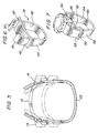
- the adjustable jeweliy ring assembly 2 of the present invention includes a bridge member 4 and a shank member 6.
- the adjustable ring of the present invention is particularly applicable to fine jewelry that may contain expensive gemstones, such as a diamond which can be mounted in a setting 10 that can be firmly attached to the bridge member 4.
- the bridge member 4 can have an arcuate shape to appropriately conform to the upper surface of the user's finger.
- This arcuate portion 12 can be attached to respective extension members 14, 16 that are appropriately dimensioned to accommodate elongated slots or apertures, to be discussed subsequently, with regards to the shank member 6.
- Mounted on each of the extension members 14, 16 is a securement member 18, 20 that will provide a load bearing surface to frictionally engage the exterior surface of the shank member 6 and to permanently secure the bridge member 4 to the shank member 6.
- the bridge member 4 as disclosed in the first embodiment can be formed from five separate individual component parts. However, it is also possible to integrally form the bridge member 4 from at least one or two pieces of metal components.
- the securement member 18, extension member 14, arcuate portion 12 and extension member 16 can be intricately cast or formed as an integral unitary component and then the plate member 20 could be installed after the integral member is mounted within the shank member 6.
- Various other configurations of the bridge member can be utilized while still achieving the purposes of the present invention.
- the setting 10 also can be subjectively configured within the creative ability of the jeweler and accordingly the particular setting 10 shown in the present embodiment should not be construed as being limiting. As shown in Figure 1 and Figure 2, the setting is proportioned to compliment the upper arcuate edge of the shank member 6 in both the uppermost and lowermost size adjustments, thus assuring an attractive presentation regardless of the adjustment.
- the bridge member 4 is moved to its upper position so that the extension members 14, 16 are approximately at the upper end of the elongated slots or apertures 28, 30. In this position, the ring can easily pass over the knuckle joint of the illustrated user's finger.
- Figure 2 discloses the position of the bridge member 4 when it has been pressed downward to snugly fit on the user's finger.
- the side members 24, 26 of the shank member 6 are biased outward to create a frictional force between the respective side members 24, 26 and the respective load bearing securement members 18, 20.
- the relative movement or displacement, d can be approximately in the range of .3 millimeters on each side.
- the vertical height, h, of the respective securement members 18, 20 are sufficient to prevent any tilt of the bridge member 4 so that it maintains a substantially constant horizontal position as it is vertically adjusted. If the vertical height of the securement members 18, 20 are narrowed sufficient to provide simply a pivot point, the bridge member 4 could then be positioned askew relative to its shank member 6 to create a flaw in the symmetry of the two part adjustable ring assembly 2 between its range of movement. While the securement members 18, 20 are shown as plate members, other configurations could be used, including a set gemstone.
- the shank member 6 can be appropriately heat treated to provide a spring force of an appropriate amount depending on the metals used.
- the shank member 6 can be biased outward or inward relative to the bridge member 4.
- the securement members 18, 20 can force the shank member 6 inward during adjustment as seen in Figures 3 and 4.
- the bridge member 4 force the shank member 6 outward as it moves vertically upward, that is the shank member 6 can be designed to be biased inward relative to the dimension of the bridge member 4.
- the edges 12a of the arcuate portion 12 will press against the interior surfaces of the shank member 6 adjacent the respective slots 28, 30 and the load plate number 18, 20 are only used for a locking purpose.
- One advantage of the biasing inward of the shank member 6 is that any possible wear or scouring of the surface of the shank member 6 by a large number of bridge member 4 adjustments will be on the interior of the ring 2 and therefore not seen by the user.
- Figures 3 and 4 represents a range of adjustment wherein Figure 3 will accommodate a size 8 ring measurement, so that the vertical internal opening height will be approximately 18.2 millimeters, while the internal opening width will be 16.3 millimeters.
- the actual exterior width of the shank member 6 displacement will be 19.2 millimeters when it is a size 8.
- Figure 4 the same ring assembly 2 is now adjusted to a size 4.5 with the exterior width of the shank member being 19.5 millimeters, its internal opening height being 13 millimeters and its internal opening width being 16.4 millimeters.
- the shank member 6 had a open width of 22 millimeters before the bridge member 4 was permanently installed through the respective elongated apertures.
- a relatively constant spring force is maintained on the bridge member 4 in view of the dimensions of the shank member 6 and the bridge member 4 as depicted in Figures 3 and 4.
- the user of the ring when moving the ring 2 as shown in Figure 1 and 2 will experience a relative constant force during the securement of the bridge member 4 during the mounting of the ring onto the finger and an adjustment to a secure fit.
- Figure 5 discloses a cross-sectional view of the combination of the bridge member 4 and the shank member 6 to disclose the relative displacements that can be achieved.
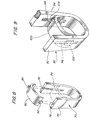
- Figure 6 discloses an alternative embodiment of the present invention and includes a shank member 36 with a bridge member 38 permanently attached in a movable manner to the shank member 36.
- the bridge member 38 includes elongated apertures 40, 42 that are dimensioned to closely fit the side members 44, 46 of the shank member 36.
- the ends 48, 50 of the respective side members 44, 46 are bent a sufficient angle to ensure that the bridge member 38 cannot be removed from the shank member 36.
- the outer surfaces of the respective apertures 40, 42 serve the purpose of providing a frictional bearing load between the spring force of the side members 44, 46 relative to the bridge member 38.
- the bridge member 38 itself can also carry additional jewels to complement any setting. It would also be possible to dimension the exterior width of the shank member 36 in an unstressed state that would be smaller than the distance between the slots 40, 42 so that the bridge member 38 provides a spring force by pushing the side members 44 and 46 apart.
- FIG. 7 A third embodiment of the present invention, which is similar in operation to that of the second embodiment, is shown in Figure 7.
- the bridge member 52 has a reduced width and is complemented with an appropriate prong setting 54 that is mounted on the bridge member 52. Respective ends of the bridge member 52 have enlarged portions 56, 58 with appropriate slots or elongated apertures 60 for providing a frictional force to side members 62, 64 of the shank member 66.
- Figure 8 discloses a fourth embodiment of the present invention and includes a shank member 70 having side members 72, 74 that are biased inward against a bridge member 80. As the bridge member 80 moves vertically along the side members from a lower to an uppermost position, it forces the side members 72, 74 outward to increase the finger size of the ring.
- the internal surfaces of the respective side members 72, 74 have an elongated dovetail slots 76, 78 respectively.
- Securement members 82, 84 are mounted on the bridge member 80 of a complimentary size to be retained within the respective dovetail slots 76, 78.
- Bridge member 80 is disclosed in an exploded perspective view to illustrate the configuration of the securement members 82, 84.
- the outer edge surfaces of the bridge member 80 actually bear against the planar interior surfaces of the side members 72, 74 to provide a secure spring force for holding a desired adjustment. While the dovetail slots or grooves are shown extending to the top of the respective side members 72, 74 it should be understood that once the bridge member 80 is mounted in the shank member 70 that the dovetailed slots are then closed at the top to leave an elongated slot that permits limited travel movement of the bridge member 80. Other configurations of grooves than a dovetail arrangement can be used.
- a shank member 90 can include a pair of rectangular cross-sectional hollow side members 92, 94.
- the side members have elongated slots 96, 98 respectively on their interior surfaces.
- a bridge member 100 is mounted between the respective side members 92, 94 and further includes keeper members 102, 104 that are captured within the hollow interior of the respective side members 92, 94.
- the keeper members 102, 104 as shown, can be in the form of plates that either act only to maintain a securement of the bridge member 100 to the shank member 90 or, alternatively, can provide load bearing surfaces against the interior planar surfaces of the side members 92, 94.
- the function of the respective keeper members 102, 104 will depend upon whether the side members 92, 94 are spring biased inward or spring biased outward. If the side members 92, 94 are biased outward, the respective keeper members 102, 104 will not only provide a securement, but will also provide a load bearing friction surface on the interior hollow planar surfaces of the respective side members 92, 94. If, however, the side members 92, 94 are biased inward, the respective ends of the bridge member 100 will provide the friction surface for exerting a force to open the side members 92, 94 as the bridge member 100 travels vertically upward. In this case, the keeper members 102, 104 will simply insure that the bridge member 100 is permanently mounted to the shank member 90.
- the present invention is particularly useful on jewelry rings where the user must first be assured of the safety of securing an expensive jewel or semi-precious stone on the bridge member to the shank member.
- the same principles of this invention can be applied to a bracelet for securing it to a wrist or an appendage of a user.
Landscapes
- Adornments (AREA)
- Saccharide Compounds (AREA)
Applications Claiming Priority (2)
| Application Number | Priority Date | Filing Date | Title |
|---|---|---|---|
| US186571 | 1998-11-05 | ||
| US09/186,571 US5943882A (en) | 1998-11-05 | 1998-11-05 | Self sizing ring |
Publications (3)
| Publication Number | Publication Date |
|---|---|
| EP1000560A2 true EP1000560A2 (de) | 2000-05-17 |
| EP1000560A3 EP1000560A3 (de) | 2000-06-07 |
| EP1000560B1 EP1000560B1 (de) | 2002-09-25 |
Family
ID=22685465
Family Applications (1)
| Application Number | Title | Priority Date | Filing Date |
|---|---|---|---|
| EP99650061A Expired - Lifetime EP1000560B1 (de) | 1998-11-05 | 1999-07-02 | Selbsteinstellbarer Ring |
Country Status (4)
| Country | Link |
|---|---|
| US (1) | US5943882A (de) |
| EP (1) | EP1000560B1 (de) |
| AT (1) | ATE224657T1 (de) |
| DE (1) | DE69903114T2 (de) |
Cited By (2)
| Publication number | Priority date | Publication date | Assignee | Title |
|---|---|---|---|---|
| RU2314004C2 (ru) * | 2003-01-28 | 2008-01-10 | Фугаку Ко., Лтд. | Четырехугольное кольцо с закругленными углами |
| KR100987140B1 (ko) | 2008-04-21 | 2010-10-11 | 임종혁 | 장식 유동형 반지 |
Families Citing this family (28)
| Publication number | Priority date | Publication date | Assignee | Title |
|---|---|---|---|---|
| AT409816B (de) * | 2000-06-21 | 2002-11-25 | Roger Roth | Mechanische innendurchmesserveränderung für schmuckobjekte |
| US6672105B1 (en) | 2001-08-28 | 2004-01-06 | Arthur A. Sills | Finger ring fit adjuster |
| US7017369B2 (en) * | 2004-06-09 | 2006-03-28 | Marthe Roberts-Shea | Ornamental ring and assembly method |
| US8061160B2 (en) * | 2004-08-17 | 2011-11-22 | Carissa Stinespring | Adjustable fashion mechanism |
| USD530237S1 (en) | 2004-10-20 | 2006-10-17 | Sobejeweled, Llc | Adjustable square ring shank assembly |
| US7523556B2 (en) * | 2004-11-22 | 2009-04-28 | Tye Larry R | Ring expansion method and device |
| US7409836B2 (en) * | 2005-01-21 | 2008-08-12 | Hearts On Fire Company | Adjustable size ring |
| US7430879B2 (en) * | 2005-01-21 | 2008-10-07 | Hearts On Fire Company | Adjustable size ring |
| US20060272356A1 (en) * | 2005-06-01 | 2006-12-07 | Lemasters Patrick A | Suspension setting for gemstones |
| US20110179825A1 (en) * | 2006-08-14 | 2011-07-28 | Shelly Avneri Katzir | Ring and method for wearing |
| US7797964B1 (en) | 2007-05-24 | 2010-09-21 | Karin Elizabeth Lynch | Ring clasp and sizer |
| USD584985S1 (en) | 2007-05-24 | 2009-01-20 | Karin Elizabeth Lynch | Ring clasp and sizer |
| CN101795595B (zh) * | 2007-08-28 | 2013-06-12 | 燃烧之心有限公司 | 可调尺寸的首饰 |
| US7845191B2 (en) * | 2007-08-28 | 2010-12-07 | Hearts On Fire Company, Llc | Adjustable sized jewelry |
| RU2374964C1 (ru) * | 2008-05-21 | 2009-12-10 | Дмитрий Юрьевич Захаров | Кольцо с подвижным декоративным элементом |
| US20100083701A1 (en) * | 2008-10-08 | 2010-04-08 | Nhan Huynh | Ring Incorporating Ring Sizing Device And Method of Use |
| AU338525S (en) * | 2011-07-08 | 2011-09-14 | Jewellery | |
| RU178850U1 (ru) * | 2017-12-26 | 2018-04-19 | Марина Викторовна Анохина | Кольцо с регулируемым размером |
| USD846422S1 (en) * | 2018-01-12 | 2019-04-23 | Cartier International Ag | Ring |
| US10905207B2 (en) * | 2018-02-15 | 2021-02-02 | Krainz Creations, Inc. | Jewelry ring having an automatic size adjusting device |
| USD890016S1 (en) * | 2018-10-16 | 2020-07-14 | Chrysos S.P.A. | Jewelry |
| US20200121038A1 (en) * | 2018-10-23 | 2020-04-23 | Cecil James Pounder, III | Jewelry |
| USD909230S1 (en) | 2018-10-23 | 2021-02-02 | Cecil James Pounder, III | Article of jewelry |
| US11064775B2 (en) * | 2018-11-26 | 2021-07-20 | Be Sunny Gifts, Llc | Jewelry device |
| EP3975832A1 (de) | 2019-06-03 | 2022-04-06 | Belum Technology (IP) Company Limited | Wearable-gesundheitsvorrichtung und verfahren dafür |
| WO2021071839A1 (en) * | 2019-10-07 | 2021-04-15 | Pt Creations | Modular rings and assembly methods thereof |
| WO2021242984A1 (en) * | 2020-05-28 | 2021-12-02 | Nouvel Heritage, Inc . | Wearable finger ring |
| USD991073S1 (en) | 2020-05-29 | 2023-07-04 | Nouvel Heritage, Sas | Wearable finger ring |
Family Cites Families (20)
| Publication number | Priority date | Publication date | Assignee | Title |
|---|---|---|---|---|
| US274193A (en) * | 1883-03-20 | Heinrich heneich | ||
| US294277A (en) * | 1884-02-26 | franz j | ||
| US322435A (en) * | 1885-07-21 | Adjustable finger-ring | ||
| US175057A (en) * | 1876-03-21 | Improvement in finger-rings | ||
| US2961855A (en) * | 1960-11-29 | Adjustable finger ring | ||
| US293874A (en) * | 1884-02-19 | Heextflch hetfrich | ||
| US293044A (en) * | 1884-02-05 | Bejfjamdf lewkowitz | ||
| DE243962C (de) * | ||||
| DE15482C (de) * | L. KOCK in Hameln a. W | Federnder Fingerring, bezw. federndes Armband | ||
| GB190418619A (en) * | 1904-08-29 | 1905-06-29 | Walter George Matthews | Improvements in Ring, Bracelet, or the like Circlets for Ornamental Personal Wear. |
| US803273A (en) * | 1905-06-21 | 1905-10-31 | Alexander Davidoff | Ring-protector. |
| US1558418A (en) * | 1925-04-22 | 1925-10-20 | Hercules Novelty Mfg Co Inc | Adjustable finger ring |
| US1695157A (en) * | 1927-06-10 | 1928-12-11 | Quast Herman | Finger ring |
| US2146272A (en) * | 1938-04-12 | 1939-02-07 | Joseph E Skoog | Adjustable finger ring |
| DE906864C (de) * | 1951-08-21 | 1954-03-18 | Friedrich Lach | Ausdehnbarer Fingerring |
| US2966048A (en) * | 1958-04-17 | 1960-12-27 | Goossev Constantin | Ring and detachably connected ring guard |
| US3246388A (en) * | 1963-06-12 | 1966-04-19 | Pasquale Arthur | Method of making an adjustable ring |
| US3959989A (en) * | 1975-02-10 | 1976-06-01 | Lawrence Peska Associates, Inc. | Ring having adjustably mounted rapidly rotatable indicia-bearing member |
| US4261185A (en) * | 1979-05-16 | 1981-04-14 | Martinez Luis M | Ring with internal means for varying size |
| FR2722070B1 (fr) * | 1994-07-06 | 1996-12-13 | Baccarat Cristalleries | Bague ajustable |
-
1998
- 1998-11-05 US US09/186,571 patent/US5943882A/en not_active Expired - Lifetime
-
1999
- 1999-07-02 AT AT99650061T patent/ATE224657T1/de not_active IP Right Cessation
- 1999-07-02 DE DE69903114T patent/DE69903114T2/de not_active Expired - Fee Related
- 1999-07-02 EP EP99650061A patent/EP1000560B1/de not_active Expired - Lifetime
Cited By (2)
| Publication number | Priority date | Publication date | Assignee | Title |
|---|---|---|---|---|
| RU2314004C2 (ru) * | 2003-01-28 | 2008-01-10 | Фугаку Ко., Лтд. | Четырехугольное кольцо с закругленными углами |
| KR100987140B1 (ko) | 2008-04-21 | 2010-10-11 | 임종혁 | 장식 유동형 반지 |
Also Published As
| Publication number | Publication date |
|---|---|
| DE69903114T2 (de) | 2003-04-30 |
| EP1000560B1 (de) | 2002-09-25 |
| US5943882A (en) | 1999-08-31 |
| EP1000560A3 (de) | 2000-06-07 |
| ATE224657T1 (de) | 2002-10-15 |
| DE69903114D1 (de) | 2002-10-31 |
Similar Documents
| Publication | Publication Date | Title |
|---|---|---|
| US5943882A (en) | Self sizing ring | |
| US6484535B2 (en) | Adjustable jewelry assembly | |
| US7861554B2 (en) | Adjustable sized jewelry | |
| US7845191B2 (en) | Adjustable sized jewelry | |
| US3115758A (en) | Finger ring with spring loaded mount for removable gems | |
| US7409836B2 (en) | Adjustable size ring | |
| US4220017A (en) | Convertible finger ring | |
| US6427487B1 (en) | Interchangeable jewelry item | |
| US20190174884A1 (en) | Earring | |
| EP2200472B1 (de) | Schmuck in verstellbarer grösse | |
| US6058737A (en) | Convertible wire earring | |
| US4974429A (en) | Combined bracelet and pendant | |
| JPWO2002065868A1 (ja) | 装身具 | |
| EP2135519B1 (de) | Fassung für abnehmbares Zierelement und eine solche Fassung aufweisendes Schmuckstück | |
| WO2018005786A1 (en) | Adjustable sized finger ring | |
| WO2009077756A1 (en) | A mounting device for a precious stone | |
| JPH0811074Y2 (ja) | 指輪兼ネックレス | |
| KR200368077Y1 (ko) | 원호형 조임턱이 구비된 장신구용 장식팁 | |
| WO2025019906A1 (en) | Jewellery band, associated accessory, and method of wearing same | |
| JP2665311B2 (ja) | 宝石用装飾台 | |
| GB2314252A (en) | Decorative locket pendant | |
| ES294231U (es) | Dispositivo perfeccionado para fijacion de adornos de bisuteria y similares | |
| GB2139873A (en) | Improvements in or relating to ear-rings | |
| GB2356551A (en) | Hinge construction of a locket | |
| HK1145614B (en) | Adjustable sized jewelry |
Legal Events
| Date | Code | Title | Description |
|---|---|---|---|
| PUAI | Public reference made under article 153(3) epc to a published international application that has entered the european phase |
Free format text: ORIGINAL CODE: 0009012 |
|
| PUAL | Search report despatched |
Free format text: ORIGINAL CODE: 0009013 |
|
| AK | Designated contracting states |
Kind code of ref document: A2 Designated state(s): AT BE CH CY DE DK ES FI FR GB GR IE IT LI LU MC NL PT SE |
|
| AX | Request for extension of the european patent |
Free format text: AL;LT;LV;MK;RO;SI |
|
| AK | Designated contracting states |
Kind code of ref document: A3 Designated state(s): AT BE CH CY DE DK ES FI FR GB GR IE IT LI LU MC NL PT SE |
|
| AX | Request for extension of the european patent |
Free format text: AL;LT;LV;MK;RO;SI |
|
| 17P | Request for examination filed |
Effective date: 20000510 |
|
| 17Q | First examination report despatched |
Effective date: 20000908 |
|
| AKX | Designation fees paid |
Free format text: AT BE CH CY DE DK ES FI FR GB GR IE IT LI LU MC NL PT SE |
|
| GRAG | Despatch of communication of intention to grant |
Free format text: ORIGINAL CODE: EPIDOS AGRA |
|
| GRAG | Despatch of communication of intention to grant |
Free format text: ORIGINAL CODE: EPIDOS AGRA |
|
| GRAH | Despatch of communication of intention to grant a patent |
Free format text: ORIGINAL CODE: EPIDOS IGRA |
|
| GRAH | Despatch of communication of intention to grant a patent |
Free format text: ORIGINAL CODE: EPIDOS IGRA |
|
| GRAA | (expected) grant |
Free format text: ORIGINAL CODE: 0009210 |
|
| AK | Designated contracting states |
Kind code of ref document: B1 Designated state(s): AT BE CH CY DE DK ES FI FR GB GR IE IT LI LU MC NL PT SE |
|
| PG25 | Lapsed in a contracting state [announced via postgrant information from national office to epo] |
Ref country code: NL Free format text: LAPSE BECAUSE OF FAILURE TO SUBMIT A TRANSLATION OF THE DESCRIPTION OR TO PAY THE FEE WITHIN THE PRESCRIBED TIME-LIMIT Effective date: 20020925 Ref country code: IT Free format text: LAPSE BECAUSE OF FAILURE TO SUBMIT A TRANSLATION OF THE DESCRIPTION OR TO PAY THE FEE WITHIN THE PRESCRIBED TIME-LIMIT;WARNING: LAPSES OF ITALIAN PATENTS WITH EFFECTIVE DATE BEFORE 2007 MAY HAVE OCCURRED AT ANY TIME BEFORE 2007. THE CORRECT EFFECTIVE DATE MAY BE DIFFERENT FROM THE ONE RECORDED. Effective date: 20020925 Ref country code: GR Free format text: LAPSE BECAUSE OF FAILURE TO SUBMIT A TRANSLATION OF THE DESCRIPTION OR TO PAY THE FEE WITHIN THE PRESCRIBED TIME-LIMIT Effective date: 20020925 Ref country code: FI Free format text: LAPSE BECAUSE OF FAILURE TO SUBMIT A TRANSLATION OF THE DESCRIPTION OR TO PAY THE FEE WITHIN THE PRESCRIBED TIME-LIMIT Effective date: 20020925 Ref country code: BE Free format text: LAPSE BECAUSE OF FAILURE TO SUBMIT A TRANSLATION OF THE DESCRIPTION OR TO PAY THE FEE WITHIN THE PRESCRIBED TIME-LIMIT Effective date: 20020925 Ref country code: AT Free format text: LAPSE BECAUSE OF FAILURE TO SUBMIT A TRANSLATION OF THE DESCRIPTION OR TO PAY THE FEE WITHIN THE PRESCRIBED TIME-LIMIT Effective date: 20020925 |
|
| REF | Corresponds to: |
Ref document number: 224657 Country of ref document: AT Date of ref document: 20021015 Kind code of ref document: T |
|
| REG | Reference to a national code |
Ref country code: GB Ref legal event code: FG4D |
|
| REG | Reference to a national code |
Ref country code: CH Ref legal event code: EP |
|
| REG | Reference to a national code |
Ref country code: IE Ref legal event code: FG4D |
|
| REF | Corresponds to: |
Ref document number: 69903114 Country of ref document: DE Date of ref document: 20021031 |
|
| PG25 | Lapsed in a contracting state [announced via postgrant information from national office to epo] |
Ref country code: SE Free format text: LAPSE BECAUSE OF FAILURE TO SUBMIT A TRANSLATION OF THE DESCRIPTION OR TO PAY THE FEE WITHIN THE PRESCRIBED TIME-LIMIT Effective date: 20021225 Ref country code: DK Free format text: LAPSE BECAUSE OF FAILURE TO SUBMIT A TRANSLATION OF THE DESCRIPTION OR TO PAY THE FEE WITHIN THE PRESCRIBED TIME-LIMIT Effective date: 20021225 |
|
| PG25 | Lapsed in a contracting state [announced via postgrant information from national office to epo] |
Ref country code: PT Free format text: LAPSE BECAUSE OF FAILURE TO SUBMIT A TRANSLATION OF THE DESCRIPTION OR TO PAY THE FEE WITHIN THE PRESCRIBED TIME-LIMIT Effective date: 20021226 |
|
| REG | Reference to a national code |
Ref country code: CH Ref legal event code: NV Representative=s name: BOVARD AG PATENTANWAELTE |
|
| NLV1 | Nl: lapsed or annulled due to failure to fulfill the requirements of art. 29p and 29m of the patents act | ||
| ET | Fr: translation filed | ||
| PG25 | Lapsed in a contracting state [announced via postgrant information from national office to epo] |
Ref country code: ES Free format text: LAPSE BECAUSE OF FAILURE TO SUBMIT A TRANSLATION OF THE DESCRIPTION OR TO PAY THE FEE WITHIN THE PRESCRIBED TIME-LIMIT Effective date: 20030328 |
|
| PG25 | Lapsed in a contracting state [announced via postgrant information from national office to epo] |
Ref country code: LU Free format text: LAPSE BECAUSE OF NON-PAYMENT OF DUE FEES Effective date: 20030702 Ref country code: IE Free format text: LAPSE BECAUSE OF NON-PAYMENT OF DUE FEES Effective date: 20030702 Ref country code: CY Free format text: LAPSE BECAUSE OF FAILURE TO SUBMIT A TRANSLATION OF THE DESCRIPTION OR TO PAY THE FEE WITHIN THE PRESCRIBED TIME-LIMIT Effective date: 20030702 |
|
| PG25 | Lapsed in a contracting state [announced via postgrant information from national office to epo] |
Ref country code: MC Free format text: LAPSE BECAUSE OF NON-PAYMENT OF DUE FEES Effective date: 20030731 |
|
| PLBE | No opposition filed within time limit |
Free format text: ORIGINAL CODE: 0009261 |
|
| STAA | Information on the status of an ep patent application or granted ep patent |
Free format text: STATUS: NO OPPOSITION FILED WITHIN TIME LIMIT |
|
| 26N | No opposition filed |
Effective date: 20030626 |
|
| REG | Reference to a national code |
Ref country code: IE Ref legal event code: MM4A |
|
| PGFP | Annual fee paid to national office [announced via postgrant information from national office to epo] |
Ref country code: DE Payment date: 20060130 Year of fee payment: 7 Ref country code: CH Payment date: 20060130 Year of fee payment: 7 |
|
| PG25 | Lapsed in a contracting state [announced via postgrant information from national office to epo] |
Ref country code: GB Free format text: LAPSE BECAUSE OF NON-PAYMENT OF DUE FEES Effective date: 20060702 |
|
| PG25 | Lapsed in a contracting state [announced via postgrant information from national office to epo] |
Ref country code: LI Free format text: LAPSE BECAUSE OF NON-PAYMENT OF DUE FEES Effective date: 20060731 Ref country code: CH Free format text: LAPSE BECAUSE OF NON-PAYMENT OF DUE FEES Effective date: 20060731 |
|
| PGFP | Annual fee paid to national office [announced via postgrant information from national office to epo] |
Ref country code: FR Payment date: 20060810 Year of fee payment: 8 |
|
| PG25 | Lapsed in a contracting state [announced via postgrant information from national office to epo] |
Ref country code: DE Free format text: LAPSE BECAUSE OF NON-PAYMENT OF DUE FEES Effective date: 20070201 |
|
| REG | Reference to a national code |
Ref country code: CH Ref legal event code: PL |
|
| GBPC | Gb: european patent ceased through non-payment of renewal fee |
Effective date: 20060702 |
|
| REG | Reference to a national code |
Ref country code: FR Ref legal event code: ST Effective date: 20080331 |
|
| PG25 | Lapsed in a contracting state [announced via postgrant information from national office to epo] |
Ref country code: FR Free format text: LAPSE BECAUSE OF NON-PAYMENT OF DUE FEES Effective date: 20070731 |
|
| PGFP | Annual fee paid to national office [announced via postgrant information from national office to epo] |
Ref country code: GB Payment date: 20060127 Year of fee payment: 7 |