EP1000667A2 - Coating apparatus and a method of assembling the same - Google Patents
Coating apparatus and a method of assembling the same Download PDFInfo
- Publication number
- EP1000667A2 EP1000667A2 EP99122232A EP99122232A EP1000667A2 EP 1000667 A2 EP1000667 A2 EP 1000667A2 EP 99122232 A EP99122232 A EP 99122232A EP 99122232 A EP99122232 A EP 99122232A EP 1000667 A2 EP1000667 A2 EP 1000667A2
- Authority
- EP
- European Patent Office
- Prior art keywords
- arm
- motor
- driving
- robot
- coating
- Prior art date
- Legal status (The legal status is an assumption and is not a legal conclusion. Google has not performed a legal analysis and makes no representation as to the accuracy of the status listed.)
- Granted
Links
Images


Classifications
-
- B—PERFORMING OPERATIONS; TRANSPORTING
- B25—HAND TOOLS; PORTABLE POWER-DRIVEN TOOLS; MANIPULATORS
- B25J—MANIPULATORS; CHAMBERS PROVIDED WITH MANIPULATION DEVICES
- B25J19/00—Accessories fitted to manipulators, e.g. for monitoring, for viewing; Safety devices combined with or specially adapted for use in connection with manipulators
- B25J19/0025—Means for supplying energy to the end effector
- B25J19/0029—Means for supplying energy to the end effector arranged within the different robot elements
-
- B—PERFORMING OPERATIONS; TRANSPORTING
- B05—SPRAYING OR ATOMISING IN GENERAL; APPLYING FLUENT MATERIALS TO SURFACES, IN GENERAL
- B05B—SPRAYING APPARATUS; ATOMISING APPARATUS; NOZZLES
- B05B13/00—Machines or plants for applying liquids or other fluent materials to surfaces of objects or other work by spraying, not covered by groups B05B1/00 - B05B11/00
- B05B13/02—Means for supporting work; Arrangement or mounting of spray heads; Adaptation or arrangement of means for feeding work
- B05B13/04—Means for supporting work; Arrangement or mounting of spray heads; Adaptation or arrangement of means for feeding work the spray heads being moved during spraying operation
- B05B13/0431—Means for supporting work; Arrangement or mounting of spray heads; Adaptation or arrangement of means for feeding work the spray heads being moved during spraying operation with spray heads moved by robots or articulated arms, e.g. for applying liquid or other fluent material to three-dimensional [3D] surfaces
-
- B—PERFORMING OPERATIONS; TRANSPORTING
- B25—HAND TOOLS; PORTABLE POWER-DRIVEN TOOLS; MANIPULATORS
- B25J—MANIPULATORS; CHAMBERS PROVIDED WITH MANIPULATION DEVICES
- B25J19/00—Accessories fitted to manipulators, e.g. for monitoring, for viewing; Safety devices combined with or specially adapted for use in connection with manipulators
-
- B—PERFORMING OPERATIONS; TRANSPORTING
- B05—SPRAYING OR ATOMISING IN GENERAL; APPLYING FLUENT MATERIALS TO SURFACES, IN GENERAL
- B05B—SPRAYING APPARATUS; ATOMISING APPARATUS; NOZZLES
- B05B12/00—Arrangements for controlling delivery; Arrangements for controlling the spray area
- B05B12/14—Arrangements for controlling delivery; Arrangements for controlling the spray area for supplying a selected one of a plurality of liquids or other fluent materials or several in selected proportions to a spray apparatus, e.g. to a single spray outlet
- B05B12/1409—Arrangements for controlling delivery; Arrangements for controlling the spray area for supplying a selected one of a plurality of liquids or other fluent materials or several in selected proportions to a spray apparatus, e.g. to a single spray outlet the selection means being part of the discharge apparatus, e.g. part of the spray gun
Definitions
- the present invention relates to coating apparatus and a method of assembling the same.
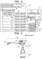
- a conventional robot for use in a coating apparatus generally includes a swivel base 40, a first vertical arm 41 extending from the swivel base 40, a second arm 42 extending from the first arm 41 in a horizontal direction, and a wrist portion 43 which is coupled to a tip of the second arm 42 and is capable of holding the coating gun.
- the swivel base 40, the first arm 41, the second arm 42 and the wrist portion 43 are movable and are driven by independent motors. Since the coating apparatus is operated in an explosion-proof area, each motor is disposed in a pressurized chamber provided in the robot.
- the pressurized chamber is filled with high pressure air, which prevents air mixed with a thinner from entering the pressurized chamber from the outside.
- a coating device including a color change valve assembly 45, a paint feed pump 46, a trigger/dump valve 47 are mounted to an outside surface of the robot via a bracket 44.
- a pressure-proof (explosion-proof) motor is used for driving the electrically-operated paint feed pump 46.
- the pressure-proof motor is relatively large in size for its motor capacity. As a result, the robot is necessarily large-sized, which may cause interference between the robot and a workpiece.
- An object of the present invention is to provide a coating apparatus which is not large-sized even though accommodated with an explosion-proof means and a method of assembling the same.
- a coating apparatus includes (a) a robot including a base, at least one movable portion, at least one motor for driving the movable portion, and at least one pressurized chamber in which the motor for driving the movable portion is disposed, and (b) a coating device including a coating gun, a paint feed pump, and a motor for driving the paint feed pump, the coating device being mounted to the robot.
- the motor for driving the paint feed pump is disposed in the pressurized chamber.
- the at least one movable portion includes a swivel base mounted on the base, an arm portion provided with the pressurized chamber, and a wrist portion which is coupled to a tip of said arm portion and is capable of holding the coating gun.
- the coating gun is coupled to the wrist portion, the paint feed pump is mounted to the arm portion, and the motor for driving the paint feed pump is disposed in the pressurized chamber provided in the arm portion.
- the arm portion includes a first arm extending from the swivel base mounted on the base and a second arm coupled to an upper end of the first arm, the second arm being provided with the pressurized chamber and having a tip to which the wrist portion is coupled.
- the motor for driving the paint feed pump is mounted to the second arm, and the motor for driving the paint feed pump and a motor for driving the wrist portion are disposed in the pressurized chamber provided in the second arm.
- a method of assembling the coating apparatus includes a step of disposing the motor for driving the wrist portion and the motor for driving the paint feed pump within the pressurized chamber when said robot is assembled.
- the coating device except the coating gun is mounted to the robot when said robot is assembled, and then the coating gun is coupled to the wrist portion to be assembled into the coating apparatus.
- the motor for driving the paint feed pump is disposed in the pressurized chamber provided in the robot, the motor is a pressurized motor which is explosion-proof. As a result, the motor is compact as compared with a conventional pressure-proof motor.
- the motor for driving the paint feed pump since the motor for driving the paint feed pump, together with the motor for driving the wrist portion, is disposed in the pressurized chamber provided in the second arm of the robot at the time of assembling the robot, the motor for driving the paint feed pump is a pressurized motor like the motor for driving the wrist portion.
- assembling the coating apparatus can be performed effectively, as compared with a conventional method where the pressure-proof motor for driving a paint feed pump is mounted to an outside surface of a robot.
- the coating apparatus except the coating gun can be assembled in a single step thereby improving productivity, as compared with a conventional method where a robot and a coating device are assembled separately.
- FIGS. 1 - 3 A coating apparatus according to an embodiment of the present invention will be explained with reference to FIGS. 1 - 3.
- the coating apparatus 1 includes a robot 10 and a coating device 20 mounted to the robot 10.
- the robot 10 includes movable portions 12 - 15, motors 12m - 15m 3 for driving the movable portions and a pressurized chamber 16 in which the motors 12m - 15m 3 are disposed.
- the coating device 20 includes a coating gun 21, a paint feed pump 22a and a motor 22b for driving the paint feed pump 22a.
- the motor 22b for driving the paint feed pump is disposed in the pressurized chamber 16 of the robot 10.
- the robot 10 includes a swivel base 12 mounted on a base 11, arm portions 13, 14 extending from the swivel base 12, and a wrist portion 15 which is coupled to a tip of the arm portions 13, 14 and is capable of holding a coating gun 21.
- the swivel base 12, the arm portions 13, 14, and the wrist portion 15 constitute movable portions.
- the arm portions include a first arm 13 extending upwardly from the swivel base 12, and a second arm 14 coupled to the first arm 13.
- the second arm 14 extends in a direction perpendicular to the first arm 13.
- the first arm 13 and the second arm 14 include spaces therein, respectively.
- the upper cover 14a is removable from the central portion.
- An inner plate 17 is disposed in the space in the central portion so as to partition the space into two chambers, i.e., an upper chamber and a lower chamber.
- the wrist portion 15 is coupled to the tip of the second arm 14, and the coating gun, such as a rotary atomizing coating gun and a rotary atomizing electrostatic coating gun, can be connected and disconnected to the wrist portion 15.
- the coating gun such as a rotary atomizing coating gun and a rotary atomizing electrostatic coating gun
- the swivel base 12 is rotated about an axis A by a motor 12m for driving the swivel base.
- the first arm 13 is oscillated about an axis B by a motor 13m for driving the first arm.
- the second arm 14 is oscillated about an axis C by a motor 14m for driving the second arm.
- the wrist portion 15 is rotated about axes D, E and F by respective motors 15m 1 , 15m 2 and 15m 3 for driving the wrist portion.
- Each motor 12m, 13m, 14m, 15m 1 , 15m 2 and 15m 3 is arranged in the pressurized chamber 16 provided in the robot 10.
- the pressurized chambers 16 is partitioned from the remaining portions by a partition wall.
- the motor 12m for driving the swivel base is provided to the partition wall defining a pressurized chamber 16a in the swivel base 12, and is disposed in the pressurized chamber 16a.
- the motor 13m for driving the first arm is provided to the partition wall defining a pressurized chamber 16b in a lower end portion of the first arm 13, and is disposed in the pressurized chamber 16b.
- the motor 14m for driving the second arm is provided to the partition wall defining a pressurized chamber 16c in an upper end portion of the first arm 13, and is disposed in the pressurized chamber 16c.
- the motors 15m 1 , 15m 2 and 15m 3 are provided to a partition wall defining a pressurized chamber 16d in the rear end portion of the second arm 14, and are disposed in the pressurized chamber 16d in parallel to each other.
- the respective pressurized chambers 16a, 16b, 16c and 16d are supplied with air having a pressure higher than an atmospheric pressure, for example about 3Pa, through an air supply hose (not shown) so as to prevent inflammable gas and explosive gas from entering the pressurized chamber.
- Air supplied to the pressurized chamber may not be exhausted.
- gas supplied into the pressurized chamber may be exhausted through an exhaust hose communicating with the pressurized chamber. In that case, the flow of supply and exhaust air is adjusted to a predetermined value.
- the respective motors 12m, 13m, 14m, 15m 1 , 15m 2 and 15m 3 are controlled and driven by a robot control panel 30, as shown in FIG. 3.
- Servo drivers 32, 33, 34, 35a, 35b, 35c for driving the respective motors 12m, 13m, 14m, 15m 1 , 15m 2 and 15m 3 , and a robot control CPU (Central Processing Unit) 37 are housed in the robot control panel 30.
- the robot control CPU 37 processes input data 36 and issues operation instructions (digital signals) to the servo drivers 32, 33, 34, 35a, 36b and 35c.
- the coating device 20 mounted to the robot 10 includes a coating gun 21, and a paint feed pump assembly 22 which includes a paint feed pump 22a and the motor 22b for driving the paint feed pump.
- the coating device 20 further includes a trigger/dump valve 23, a color change valve assembly 24, and a paint feed hose 25.
- the coating gun 21 includes a paint nozzle 21a which can communicate with the paint feed hose 25 disposed in the robot 10.
- the paint feed pump 22a is driven by the motor 22b so that the paint feed pump assembly 22 feeds a constant quantity of paint.
- the motor 22b for driving the paint feed pump is driven by a servo driver 39 housed in the robot control panel 30.
- a flushable gear pump (FGP) which can be self-cleaned, may be used as the paint feed pump 22a.
- the trigger/dump valve 23 includes a trigger valve which permits a paint and the like to flow into a paint hose communicating with the coating gun 21 and a dump valve which permits the paint and the like to flow into a recycling path.
- the color change valve assembly 24 includes a plurality of paint valves for switching ON/OFF of paint supply from respective paint paths extending from paint tanks (not shown) corresponding to paint colors to be coated, a thinner valve for switching ON/OFF of thinner supply, and an air valve for switching ON/OFF of air supply.
- the paint feed hose 25 extends from the color change valve assembly 24 and feeds paint to the coating gun 21.
- the paint feed hose 24 is provided with a FGP 22a and the trigger/dump valve 23 in its intermediate portion.
- the color change valve assembly 24, the FGP 22a and the trigger/dump valve 23 are arranged in the second arm 14 of the arm portions. However, it is to be understood that this is not the only arrangement possible. Preferably, the color change valve assembly 24, the FGP 22a and the trigger/dump valve 23 are arranged in that order from upstream in a flow direction of paint.
- the paint feed hose 25 is disposed between the color change valve assembly 24 and the FGP 22a, and between the FGP 22a and the trigger/dump valve 23.
- the color change valve assembly 24, the FGP 22a, the trigger/dump valve 23 and the paint feed hose 25 may be mounted outside the second arm 14, it is preferable that, as illustrated in FIG. 1, they are disposed within the second arm 14 utilizing the space in the second arm 14. Due to this structure, paint mist is prevented from adhering to the coating device 20 during coating.
- the color change valve assembly 24, the FGP 22a and the trigger/dump valve 23 may be disposed on an upper surface of the inner plate 17.
- the color change valve assembly 24, the FGP 22a and the trigger/dump valve 23 are arranged parallel to each other in the axial direction.
- the motor 22b for driving the FGP is disposed in the pressurized chamber 16 provided in the robot 10.
- the motor 22b for driving the FGP is provided to the partition wall of the pressurized chamber 16d which has previously been formed in the rear end portion of the second arm 14 for arrangement of the motors 15m 1 , 15m 2 and 15m 3 for driving the wrist portion, and is disposed in the pressurized chamber 16d, together with the motors 15m 1 , 15m 2 and 15m 3 for driving the wrist portion.
- the motors 15m 1 , 15m 2 and 15m 3 for driving the wrist portion are disposed in a lower portion of the pressurized chamber 16d, and the motor 22b for driving the FGP is disposed in an upper portion of the pressurized chamber 16d.
- the motor 22b for driving the FGP is controlled by the servo driver 39 housed in the robot control panel 30.
- a paint discharge level according to computer program is compared with a value on a paint discharge data table 38 and the instructions (digital signals) are fed to the servo driver 39.
- the discharge data table 38 determines paint discharge quantity according to a color to be coated and the paint discharge level.
- Three power shafts 18 connected to the motors 15m 1 , 15m 2 and 15m 3 for driving the wrist portion and transmitting power to the wrist portion 15 are disposed in the space in the second arm 14.
- the paint feed pump 22a and the trigger/dump valve 23 are disposed in the upper chamber located in an upper side of the inner plate 17, the power shafts 18 are disposed in the lower chamber located in a lower side of the inner plate 17.
- a power shaft 26 coupled to the motor 22b for driving the FGP and transmitting power to the FGP 22a is disposed in the space in the second arm 14.
- the power shaft 26 is disposed in the lower chamber located in the lower side of the inner plate 17 at a position where the power shaft 26 does not interfere with the power shafts 18, for example, at a position located above the power shaft 18.
- a front portion of the power shaft 26 is supported by a bearing 27.
- a tip of the power shaft 26 is constructed of, for example, a bevel gear 28, through which power is transmitted to the FGP 22a located above the power shaft 26. Transmission of power from the motor 22b to the FGP 22a is not limited to the above-described means and may be performed by a flexible shaft.
- a robot locus, a robot speed and a paint discharge corresponding to a configuration of a workpiece are optionally fed to the robot control CPU 37 housed in the robot control panel 30.
- operation instructions are fed from the robot control CPU 37 to the respective servo drivers 32, 33, 34, 35a, 35b and 35c for driving the respective motors 12m, 13m, 14m, 15m 1 , 15m 2 and 15m 3 for diving the respective movable portions 12, 13, 14 and 15.
- operation instructions are fed from the robot control CPU 37 to the servo diver 39 for diving the motor 22b via the discharge data table 38. This causes any movable portion of the movable portions 12, 13, 14 and 15 receiving operation instructions to be driven.
- the thinner valve and the air valve is alternately switched ON, which allows thinner and air to flow into the paint feed hose 25 and the FGP 22a, respectively, so as to clean them.
- the dump valve of the trigger/dump valve 23 is turned ON, the paint and the thinner flowing from an upstream direction flow into the recycling path.
- the motor 22b for driving the FGP which is a pressurized motor
- the motor 22b for driving the FGP is compact as compared with the conventional FGP of a pressure-proof motor. As a result, the coating apparatus can be compact.
- the coating apparatus 1 is lightened, so that the capacity of each motor for driving the respective movable portions of the robot can be reduced.
- the FGP 22a and the trigger/dump valve 23 are arranged in that order from upstream in a flow direction of paint so as to be spaced from each other over a relatively short distance, the paint feed hose 25 extending from the color change valve assembly 24 to the coating gun 21 coupled to the tip of the wrist portion 15 is shortened, so that the amount of paint to be dumped can be reduced when the paint color is changed.
- the FGP 22a and the trigger/dump valve 23 are arranged on the same plane in that order from upstream in a flow direction of paint, the amount of paint to be dumped can be further reduced.
- the servo driver 39 driving the motor for driving the paint feed pump is housed in the robot control panel 30, so that the servo driver 39 is controlled by digital signals.
- the control system is more simplified than a coating apparatus provided with the conventional paint feed pump in which the servo driver for the motor driving the paint feed pump is not housed in the robot control panel and a digital to analog conversion device is necessary.
- the base 11, the swivel base 12, the first arm 13, the second arm 14 and the wrist portion 15 are assembled into the robot 10.
- the motor 22b for driving the FGP is provided to the partition wall of the pressurized chamber 16d which has previously been formed for arrangement of the motors 15m 1 , 15m 2 and 15m 3 for driving the wrist portion, and is disposed in the pressurized chamber 16d together with the motors 15m 1 , 15m 2 and 15m 3 for driving the wrist portion.
- the color change valve assembly 24, the FGP 22a, the trigger/dump valve 23 and a paint feed hose 25 are provided to the second arm 14.
- the inner plate 17 is disposed in a state that an upper cover 14a of the second arm 14 is demounted and the upper cover 14a is then mounted to the second arm 14.
- the second arm 14 mounted with the coating device except the coating gun is obtained.
- the coating apparatus 1 in a state that the coating gun 21 is not coupled thereto is assembled by a robot maker. Then, the coating apparatus 1 in that state is sent to a user of the coating apparatus, by whom an optional coating gun 21 is coupled thereto, so that the coating apparatus is practically usable. Therefore, the method of the present invention provides a simple method for assembling the coating apparatus, as compared with a conventional assembly method including a plurality of steps where only a robot is assembled by a robot maker, and coating device is then mounted to the robot by a coating device maker to be assembled into a coating apparatus. Accordingly, assembling the coating apparatus can be performed effectively, and the productivity is improved.
- the motor for driving the paint feed pump is disposed in the pressurized chamber, a pressurized motor can be used. As a result, the motor is compact as compared with the conventional pressure-proof motor, which enables the coating apparatus to be compact.
- the motor for driving the paint feed pump is disposed in the pressurized chamber together with the motor for driving the wrist portion at the time of assembling the robot, assembling the coating apparatus can be performed effectively, as compared with the conventional method where the pressure-proof motor for driving the paint feed pump is mounted outside the robot.
- the coating apparatus except the coating gun can be assembled at a single step thereby improving the productivity, as compared with the conventional method where the robot and the coating device are assembled separately.
- a coating apparatus (1) includes (a) a robot (10) including at least one movable portion (12, 13, 14, 15), at least one motor (12m, 13m, 14m, 15m 1 , 15m 2 , 15m 3 ) for driving the movable portion (12, 13, 14, 15), and at least one pressurized chamber (16) in which the motor (12m, 13m, 14m, 15m 1 , 15m 2 , 15m 3 ) for driving the movable portion (12, 13, 14, 15) is disposed; and (b) a coating device (20) including a coating gun (21), a paint feed pump (22a) and a motor (22b) for driving the paint feed pump (22a), the coating device (20) being mounted to the robot (10).
- the motor (22b) for driving the paint feed pump (22a) is disposed in the pressurized chamber (16).
Landscapes
- Engineering & Computer Science (AREA)
- Robotics (AREA)
- Mechanical Engineering (AREA)
- Spray Control Apparatus (AREA)
- Manipulator (AREA)
- Nozzles (AREA)
Abstract
Description
However, the pressure-proof motor is relatively large in size for its motor capacity. As a result, the robot is necessarily large-sized, which may cause interference between the robot and a workpiece.
Claims (7)
- A coating apparatus (1) comprising:a robot (10) including a base (11), at least one movable portion (12, 13, 14, 15), at least one motor (12m, 13m, 14m, 15m1, 15m2, 15m3) for driving said at least one movable portion (12, 13, 14, 15), and at least one pressurized chamber (16) in which said at least one motor (12m, 13m, 14m, 15m1, 15m2, 15m3) for driving said at least one movable portion (12, 13, 14, 15) is disposed; anda coating device (20) including a coating gun (21), a paint feed pump (22a), and a motor (22b) for driving said paint feed pump, said coating device (20) being mounted to said robot (10),
wherein said motor (22a) for diving said paint feed pump (22a) is disposed in said at least one pressurized chamber (16). - A coating apparatus (1) according to claim 1, wherein said at least one movable portion (12, 13, 14, 15) includes a swivel base (12) mounted on said base (11), an arm portion (13, 14) provided with said at least one pressurized chamber (16) and having a tip, and a wrist portion (15) which is coupled to the tip of said arm portion (13, 14) and is capable of holding said coating gun (21),
wherein said coating gun (21) is coupled to said wrist portion (15), said paint feed pump (22a) is mounted to said arm portion (13, 14), and said motor (22b) for driving said paint feed pump (22a) is disposed in said at Least one pressurized chamber (16) provided in said arm portion (13, 14). - A coating apparatus (1) according to claim 2, wherein said arm portion (13, 14) includes a first arm (13) extending from said swivel base (12) mounted on said base (11) and having an upper end, and a second arm (14) coupled to the upper end of said first arm (13), said second arm (14) being provided with said at least one pressurized chamber (16d) and having a tip to which said wrist portion (15) is coupled,
wherein said motor (22b) for driving said paint feed pump (22a) is mounted to said second arm (14), and said motor (22b) for driving said paint feed pump (22a) and a motor (15m1, 15m2, 15m3) for driving said wrist portion (15) are disposed in said at least one pressurized chamber (16d) provided in said second arm (14). - A method of assembling a coating apparatus (1) which includes (a) a robot (10) having a base (11), a swivel base (12) mounted on said base (11), a first arm (13) extending from said swivel base (12), a second arm (14) having a pressurized chamber (16d) and coupled to said first arm (13), and a wrist portion (15) coupled to a tip of said second arm (14), and (b) a coating device (20) including a coating gun (21), a paint feed pump (22a), and a motor (22b) for driving said paint feed pump (22a), said coating device (20) being mounted to said robot (10), said method comprising:disposing a motor (15m1, 15m2, 15m3) for driving said wrist portion (15) and said motor (22b) for driving said paint feed pump (22a) within said pressurized chamber (16d), when said robot (10) is assembled.
- A method of assembling a coating apparatus (1) according to claim 4, further comprising:mounting said coating device (20) except said coating gun (21) to said robot (10) when said robot (10) is assembled; andcoupling said coating gun (21) to said wrist portion (15) to be assembled into said coating apparatus (1).
- A coating apparatus (1) according to claim 3, wherein said paint feed pump (22a) of said coating device (20) is mounted outside said second arm (14).
- A coating apparatus (1) according to claim 3, wherein said paint feed pump (22a) is provided in said second arm (14).
Applications Claiming Priority (4)
| Application Number | Priority Date | Filing Date | Title |
|---|---|---|---|
| JP32356598 | 1998-11-13 | ||
| JP32356598 | 1998-11-13 | ||
| JP13857499A JP3513050B2 (en) | 1998-11-13 | 1999-05-19 | Painting robot and assembly method of painting robot |
| JP13857499 | 1999-05-19 |
Publications (3)
| Publication Number | Publication Date |
|---|---|
| EP1000667A2 true EP1000667A2 (en) | 2000-05-17 |
| EP1000667A3 EP1000667A3 (en) | 2002-06-12 |
| EP1000667B1 EP1000667B1 (en) | 2004-05-19 |
Family
ID=26471582
Family Applications (1)
| Application Number | Title | Priority Date | Filing Date |
|---|---|---|---|
| EP99122232A Revoked EP1000667B1 (en) | 1998-11-13 | 1999-11-08 | Coating apparatus and a method of assembling the same |
Country Status (3)
| Country | Link |
|---|---|
| EP (1) | EP1000667B1 (en) |
| JP (1) | JP3513050B2 (en) |
| DE (1) | DE69917411T2 (en) |
Cited By (5)
| Publication number | Priority date | Publication date | Assignee | Title |
|---|---|---|---|---|
| WO2002092236A3 (en) * | 2001-05-16 | 2003-02-20 | Fanuc Robotics North America | Voltage block and color change apparatus for waterborne bell applicator |
| EP1502658A1 (en) | 2003-07-28 | 2005-02-02 | Dürr Systems GmbH | Spraying device comprising a colour changer for coating series of work pieces |
| US8333164B2 (en) | 2006-12-12 | 2012-12-18 | Duerr Systems, Gmbh | Coating apparatus comprising a metering device |
| CN112064993A (en) * | 2020-09-09 | 2020-12-11 | 湖州拓高机械有限公司 | Handheld wall paint spraying device convenient for adjusting coating amount |
| US11707756B2 (en) | 2017-02-09 | 2023-07-25 | Kabushiki Kaisha Yaskawa Denki | Coating system having plurality of coating robots and operation robot having five arms and tip jig |
Families Citing this family (11)
| Publication number | Priority date | Publication date | Assignee | Title |
|---|---|---|---|---|
| DE202006021283U1 (en) | 2005-10-07 | 2014-10-02 | Dürr Systems GmbH | Coating material supply device |
| DE102005060959B4 (en) * | 2005-10-07 | 2024-11-21 | Dürr Systems Ag | Coating agent supply device and associated operating procedure |
| US8020784B2 (en) | 2005-10-07 | 2011-09-20 | Durr Systems Inc. | Coating material supply installation and associated operating procedure |
| DE102006043604B4 (en) * | 2006-09-16 | 2014-02-27 | Eisenmann Ag | Carrying device and robot with such a support device |
| DE102006058562A1 (en) | 2006-12-12 | 2008-08-14 | Dürr Systems GmbH | Coating device for serially coating workpieces with different shades comprises a separate color changer containing color valves to which are connected color lines for the coating material |
| DE102007029195A1 (en) | 2007-06-25 | 2009-02-19 | Dürr Systems GmbH | Coating device for serially coating workpieces with different shades comprises a separate color changer containing color valves to which are connected color lines for the coating material |
| JP6068548B2 (en) * | 2015-04-09 | 2017-01-25 | ファナック株式会社 | An articulated robot in which connecting members for connecting the striatum are arranged on the arm |
| CN105216009A (en) * | 2015-11-06 | 2016-01-06 | 重庆大学 | Spray robot arm member |
| JP6791038B2 (en) * | 2017-06-22 | 2020-11-25 | トヨタ車体株式会社 | Diagnostic system and diagnostic method for open / close valves for bell-shaped coating machines |
| KR102177618B1 (en) * | 2018-12-17 | 2020-11-11 | 주식회사 포스코 | Apparatus for protecting robot arm |
| CN115351792A (en) * | 2022-08-03 | 2022-11-18 | 北京炎凌嘉业机电设备有限公司 | Movable explosion-proof robot for spraying large-scale target body |
Family Cites Families (4)
| Publication number | Priority date | Publication date | Assignee | Title |
|---|---|---|---|---|
| CA1251243A (en) * | 1985-01-22 | 1989-03-14 | Hadi A. Akeel | Electric robot for use in a hazardous location |
| US5212432A (en) * | 1989-10-20 | 1993-05-18 | Tokico, Ltd. | Industrial robot |
| US5656085A (en) * | 1995-11-27 | 1997-08-12 | Behr Systems, Inc. | Paint spray apparatus with remote pump drive |
| JPH10138190A (en) * | 1996-09-11 | 1998-05-26 | Nachi Fujikoshi Corp | Explosion-proof electric robot |
-
1999
- 1999-05-19 JP JP13857499A patent/JP3513050B2/en not_active Expired - Fee Related
- 1999-11-08 EP EP99122232A patent/EP1000667B1/en not_active Revoked
- 1999-11-08 DE DE69917411T patent/DE69917411T2/en not_active Expired - Lifetime
Non-Patent Citations (1)
| Title |
|---|
| None |
Cited By (6)
| Publication number | Priority date | Publication date | Assignee | Title |
|---|---|---|---|---|
| WO2002092236A3 (en) * | 2001-05-16 | 2003-02-20 | Fanuc Robotics North America | Voltage block and color change apparatus for waterborne bell applicator |
| EP1502658A1 (en) | 2003-07-28 | 2005-02-02 | Dürr Systems GmbH | Spraying device comprising a colour changer for coating series of work pieces |
| US7140559B2 (en) | 2003-07-28 | 2006-11-28 | Behr Systems, Inc. | Spraying device for serial spraying of work pieces |
| US8333164B2 (en) | 2006-12-12 | 2012-12-18 | Duerr Systems, Gmbh | Coating apparatus comprising a metering device |
| US11707756B2 (en) | 2017-02-09 | 2023-07-25 | Kabushiki Kaisha Yaskawa Denki | Coating system having plurality of coating robots and operation robot having five arms and tip jig |
| CN112064993A (en) * | 2020-09-09 | 2020-12-11 | 湖州拓高机械有限公司 | Handheld wall paint spraying device convenient for adjusting coating amount |
Also Published As
| Publication number | Publication date |
|---|---|
| DE69917411T2 (en) | 2005-07-14 |
| JP3513050B2 (en) | 2004-03-31 |
| EP1000667A3 (en) | 2002-06-12 |
| JP2000202337A (en) | 2000-07-25 |
| DE69917411D1 (en) | 2004-06-24 |
| EP1000667B1 (en) | 2004-05-19 |
Similar Documents
| Publication | Publication Date | Title |
|---|---|---|
| EP1000667B1 (en) | Coating apparatus and a method of assembling the same | |
| US6328799B1 (en) | Coating apparatus and a method of assembling the same | |
| US5421218A (en) | Electric robot for use in a hazardous location | |
| EP2422886B1 (en) | Nozzle rotation mechanism and coating device provided therewith | |
| WO2019213614A1 (en) | Robotic electrostatic painting apparatus | |
| US20070243075A1 (en) | Carrying system and processing equipment | |
| US6477913B1 (en) | Electric robot for use in a hazardous location | |
| JPS6125653A (en) | Electrostatic type spray device mounted to robot | |
| US11420744B2 (en) | Automated drone-based paint delivery system | |
| JPS61168492A (en) | Electric robot used for hazardous position | |
| US7051950B2 (en) | Atomizer for coating unit and method for its material supply | |
| CN110997156A (en) | Coating system and coating method | |
| US5225239A (en) | Electrostatic spray coating apparatus for applying two component mixture | |
| JP6835805B2 (en) | Paint filling device for cartridges | |
| EP0535604B1 (en) | Wrist mechanism of industrial robot | |
| US6942161B2 (en) | Painting machine for use with powder paint | |
| JP2000350968A (en) | Work washing apparatus comprising plural spraying nozzles | |
| US5236504A (en) | Device for the spray-coating of objects | |
| AU608466B2 (en) | Electrostatic spray coating apparatus for applying two component mixture | |
| JP4701574B2 (en) | Multicolor small quantity coating system | |
| JP3812700B2 (en) | Painting robot | |
| KR101771072B1 (en) | Hybrid vehicle for painting line | |
| JP3988004B2 (en) | Painting robot | |
| US20250121394A1 (en) | Solvent push floating piston | |
| JP2010274248A (en) | Painting system |
Legal Events
| Date | Code | Title | Description |
|---|---|---|---|
| PUAI | Public reference made under article 153(3) epc to a published international application that has entered the european phase |
Free format text: ORIGINAL CODE: 0009012 |
|
| 17P | Request for examination filed |
Effective date: 19991108 |
|
| AK | Designated contracting states |
Kind code of ref document: A2 Designated state(s): AT BE CH CY DE DK ES FI FR GB GR IE IT LI LU MC NL PT SE |
|
| AX | Request for extension of the european patent |
Free format text: AL;LT;LV;MK;RO;SI |
|
| RAP1 | Party data changed (applicant data changed or rights of an application transferred) |
Owner name: KAWASAKI JUKOGYO KABUSHIKI KAISHA Owner name: TOYOTA JIDOSHA KABUSHIKI KAISHA |
|
| PUAL | Search report despatched |
Free format text: ORIGINAL CODE: 0009013 |
|
| AK | Designated contracting states |
Kind code of ref document: A3 Designated state(s): AT BE CH CY DE DK ES FI FR GB GR IE IT LI LU MC NL PT SE |
|
| AX | Request for extension of the european patent |
Free format text: AL;LT;LV;MK;RO;SI |
|
| RIC1 | Information provided on ipc code assigned before grant |
Free format text: 7B 05B 13/04 A, 7B 25J 9/00 B, 7B 25J 19/00 B |
|
| AKX | Designation fees paid |
Designated state(s): DE SE |
|
| GRAP | Despatch of communication of intention to grant a patent |
Free format text: ORIGINAL CODE: EPIDOSNIGR1 |
|
| GRAS | Grant fee paid |
Free format text: ORIGINAL CODE: EPIDOSNIGR3 |
|
| GRAA | (expected) grant |
Free format text: ORIGINAL CODE: 0009210 |
|
| AK | Designated contracting states |
Kind code of ref document: B1 Designated state(s): DE SE |
|
| REG | Reference to a national code |
Ref country code: SE Ref legal event code: TRGR |
|
| REG | Reference to a national code |
Ref country code: IE Ref legal event code: FG4D |
|
| REF | Corresponds to: |
Ref document number: 69917411 Country of ref document: DE Date of ref document: 20040624 Kind code of ref document: P |
|
| PLAQ | Examination of admissibility of opposition: information related to despatch of communication + time limit deleted |
Free format text: ORIGINAL CODE: EPIDOSDOPE2 |
|
| PLAR | Examination of admissibility of opposition: information related to receipt of reply deleted |
Free format text: ORIGINAL CODE: EPIDOSDOPE4 |
|
| PLBQ | Unpublished change to opponent data |
Free format text: ORIGINAL CODE: EPIDOS OPPO |
|
| PLBI | Opposition filed |
Free format text: ORIGINAL CODE: 0009260 |
|
| PLAX | Notice of opposition and request to file observation + time limit sent |
Free format text: ORIGINAL CODE: EPIDOSNOBS2 |
|
| 26 | Opposition filed |
Opponent name: DUERR SYSTEMS GMBH Effective date: 20050216 |
|
| PLAF | Information modified related to communication of a notice of opposition and request to file observations + time limit |
Free format text: ORIGINAL CODE: EPIDOSCOBS2 |
|
| PLBB | Reply of patent proprietor to notice(s) of opposition received |
Free format text: ORIGINAL CODE: EPIDOSNOBS3 |
|
| PGFP | Annual fee paid to national office [announced via postgrant information from national office to epo] |
Ref country code: DE Payment date: 20101104 Year of fee payment: 12 |
|
| REG | Reference to a national code |
Ref country code: DE Ref legal event code: R103 Ref document number: 69917411 Country of ref document: DE Ref country code: DE Ref legal event code: R064 Ref document number: 69917411 Country of ref document: DE |
|
| RDAF | Communication despatched that patent is revoked |
Free format text: ORIGINAL CODE: EPIDOSNREV1 |
|
| PGFP | Annual fee paid to national office [announced via postgrant information from national office to epo] |
Ref country code: SE Payment date: 20111115 Year of fee payment: 13 |
|
| RDAG | Patent revoked |
Free format text: ORIGINAL CODE: 0009271 |
|
| STAA | Information on the status of an ep patent application or granted ep patent |
Free format text: STATUS: PATENT REVOKED |
|
| 27W | Patent revoked |
Effective date: 20111010 |
|
| REG | Reference to a national code |
Ref country code: DE Ref legal event code: R107 Ref document number: 69917411 Country of ref document: DE Effective date: 20120628 |
|
| REG | Reference to a national code |
Ref country code: SE Ref legal event code: ECNC |