EP1005055A2 - Illuminated pushbutton with colors and brightness electronically controlled - Google Patents
Illuminated pushbutton with colors and brightness electronically controlled Download PDFInfo
- Publication number
- EP1005055A2 EP1005055A2 EP99830712A EP99830712A EP1005055A2 EP 1005055 A2 EP1005055 A2 EP 1005055A2 EP 99830712 A EP99830712 A EP 99830712A EP 99830712 A EP99830712 A EP 99830712A EP 1005055 A2 EP1005055 A2 EP 1005055A2
- Authority
- EP
- European Patent Office
- Prior art keywords
- pushbutton
- display
- illuminated
- switch
- actuator
- Prior art date
- Legal status (The legal status is an assumption and is not a legal conclusion. Google has not performed a legal analysis and makes no representation as to the accuracy of the status listed.)
- Withdrawn
Links
Images


Classifications
-
- H—ELECTRICITY
- H01—ELECTRIC ELEMENTS
- H01H—ELECTRIC SWITCHES; RELAYS; SELECTORS; EMERGENCY PROTECTIVE DEVICES
- H01H13/00—Switches having rectilinearly-movable operating part or parts adapted for pushing or pulling in one direction only, e.g. push-button switch
- H01H13/02—Details
- H01H13/023—Light-emitting indicators
-
- H—ELECTRICITY
- H01—ELECTRIC ELEMENTS
- H01H—ELECTRIC SWITCHES; RELAYS; SELECTORS; EMERGENCY PROTECTIVE DEVICES
- H01H13/00—Switches having rectilinearly-movable operating part or parts adapted for pushing or pulling in one direction only, e.g. push-button switch
- H01H13/02—Details
- H01H13/023—Light-emitting indicators
- H01H2013/026—Light-emitting indicators with two or more independent lighting elements located inside the push button switch that illuminate separate zones of push buttons
-
- H—ELECTRICITY
- H01—ELECTRIC ELEMENTS
- H01H—ELECTRIC SWITCHES; RELAYS; SELECTORS; EMERGENCY PROTECTIVE DEVICES
- H01H2217/00—Facilitation of operation; Human engineering
- H01H2217/032—Feedback about selected symbol, e.g. display
-
- H—ELECTRICITY
- H01—ELECTRIC ELEMENTS
- H01H—ELECTRIC SWITCHES; RELAYS; SELECTORS; EMERGENCY PROTECTIVE DEVICES
- H01H2219/00—Legends
- H01H2219/054—Optical elements
- H01H2219/056—Diffuser; Uneven surface
-
- H—ELECTRICITY
- H01—ELECTRIC ELEMENTS
- H01H—ELECTRIC SWITCHES; RELAYS; SELECTORS; EMERGENCY PROTECTIVE DEVICES
- H01H2219/00—Legends
- H01H2219/054—Optical elements
- H01H2219/06—Reflector
-
- H—ELECTRICITY
- H01—ELECTRIC ELEMENTS
- H01H—ELECTRIC SWITCHES; RELAYS; SELECTORS; EMERGENCY PROTECTIVE DEVICES
- H01H2219/00—Legends
- H01H2219/054—Optical elements
- H01H2219/062—Light conductor
-
- H—ELECTRICITY
- H01—ELECTRIC ELEMENTS
- H01H—ELECTRIC SWITCHES; RELAYS; SELECTORS; EMERGENCY PROTECTIVE DEVICES
- H01H2231/00—Applications
- H01H2231/016—Control panel; Graphic display; Program control
Definitions
- the invention relates an illuminated pushbutton with variable color lights electronically controlled, where the light is emitted utilizing solid state devices.
- Momentary action or alternate action switch is realized without electromechanical commutation.
- “Momentary action” means the generation of an electrical or electronic signal for all the time the button is maintained active.
- “Alternate action” means the generation of an electrical or electronic signal which changes the state each time the pushbutton is pushed.
- the illuminated part consists of a display which can be divided in independent zones, illuminated with visible light, generated inside of the button, having any wave length programmable in an operative, semi-operative or fixed way, independently for each zone.
- the zones can be of any number.
- the pushbutton described in the following is the version divided in four zones.
- the invention lies in the field of the electronic devices and can find application where it is necessary dispose of command/control illuminated pushbuttons; in mechanical, electrical and electronic equipments. It can be used in any operative ambient. Regarding naval, avionical, space fields, it must underline that the invention has the requirement to be used in said sectors, for instance, said pushbutton can support any stress even when the device is in operation.
- the invention represents a new step in the planning and realization technique of the control pushbutton: the display light is obtained by a solid state components.
- the pushbutton configuration is such that the zones can be colored with one of the wished colors, and these colors can be electrically changed depending on the user needs.
- the push buttons known until now in the market, at least known by the inventors, are constituted by switch and display, but the switch generally is mechanical and then the commutations number has a limited life of mechanical parts, for instance with mechanical contacts and springs. Mechanical and electrical bounces of commutation are unwanted negative effects.
- the part activated by the operator is illuminated by lamps which generate a base light similar to the white and to obtain different coloration, filters and optical corrections are employed. Said lamps do not allow to generate changes in the emitted light coloration, but only the light emission in a color or missing light. In this way the base requirement, necessary for the operative application which is to dispose with a display always illuminated with light which can change color and brightness, is not obtained.
- operative rules and the human engineering prescriptions require for operative readout of any information the use of lighting of different coloration and brightness in dependence on the operative meaning of the same. For instance, white light to permit the reading of the information and the identification of the command by the operator; red light to readout alarm states and variable lighting (green, blue, amber, etc) depending on the operative conditions.
- Lamps have a limited operative life, because of their employing needs a frequent access into the internal parts of the illuminated pushbutton for the replacement of the failed lams. With the necessity of active maintainability plan.
- This illuminated pushbutton is also created to be employed in cockpits and in command and control panels in mechanical and electric and electronic equipments.
- the display illumination is one of the original aspects. It is obtained by solid state components, through which it is possible produce light of any color, even white.
- the display as unlimited working life, with respect to previous solutions:
- the display is subdivided in zones, and can be illuminated independently both for luminosity and color:
- this pushbutton can change many configuration just modifying the internal electronic circuits. For instance, properly modifying the electronic circuits is obtained :
- An other advantage of this invention is that the illuminated pushbuttons can be applied on panels, singularly or in matrix, utilizing in this last case a proper container.
- the version in matrix realizing in a firm, offers better compactness and, reduction of the space, weight, costs and a better quality for the smaller number of the parts utilized.
- the input-output pushbutton connections are realized by direct coupling throw motherboards or crimp connectors.
- Fig. 1 Side view of the pushbutton.
- Fig. 4 Exploited view of the display.
- Fig. 5 Exploited view of the pushbutton.
- Fig. 6 Some configurations of the display.
- Fig. 7 Pushbutton housing for matrix assembly.
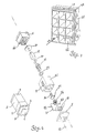
- the display assembly 5 constituted by a movable part 3 and a fixed part 4, includes the flange 2 for panel mounting 36 and it is united to the switch assembly 6 to constitute the pushbutton.
- the clamping spacer 8, clamped by the cam 9, is the contrasting element of the flange 2, used to fix the pushbutton on the panel 36 and the compression of the seal mounting gasket 11.
- the pushbutton is closed on the rear side by a cover 7. Also the input-output connector 10 is on this side.
- the pushbutton illuminated area 1, the flange 2 and the movable part of the display can be seen.
- the pushbutton is constituted as follows:
- the vertical axis movement of the actuator is guided by the actuator slide guide 29.
- the actuator slide guide 29 and the washer 50 protect even the metallic parts, as they are in plastic material or similar, to be damaged by wear and abrasion.
- the pushbutton electrical connections are realized by the flexible circuit 23 and the electronic parts 30.
- the connector 22 connects the display assembly with the switch.
- the electronic parts are housed in the zones 26.
- the electric connections of the pushbutton to the external, are realized by connector/connectors 10 mounted on the flexible circuit 23.
- Fig. 6 shows some of the many configurations in which the display can be realized.
- Fig. 7 represents one example of matrix housing 45 for assembly single pushbutton 46 matrix installation.
- the example shows a four rows-three columns matrix. It can contain so twelve single pushbutton. Each pushbutton inserts in the direction of the insertion 47 showed and when assembled, it reaches the position represented 46. Even the flange 48 of this matrix has a gasket to avoid contamination by external agents.
- Fig. 8 shows a pushbutton matrix assembled during the manufacturing. It is the version with four rows and two columns, that is with eight lighting pushbuttons.
- the pushbutton activation happens applying a proper pressure on the element 1.
- This action causes the shifting of the movable part 3 and then the movement on the axis of the switch actuator 25, the pressure on the switch 24 until the activation and then the generation of the signal electrical command.
- the travel of the display movable part is limited by the mechanical block realized between spring guide 32 and the actuator slide 29, while the spring 33 provides the reinstatement of the initial position of the pushbutton when the action of pressure on the element 1 stops.
- the lighting is activated by electronic command applied through the connector 10, the flexible 24, electronic parts 30, connector 22, flexible 16, solid state clement 15 like leds or similar components.
Landscapes
- Push-Button Switches (AREA)
- Illuminated Signs And Luminous Advertising (AREA)
- Luminescent Compositions (AREA)
Abstract
Description
- the pushbutton has a display made of solid state components able to supply light, for instance leds, in the colors, red, green and blue, by mixing them; any light color in the visible light spectrum can be generated without using filters. (Even the lightness can be electronically controlled).
- the color commutation and intensity are obtained electronically;
- it allows the activation of electric/electronic commutation devices, as means of conductive robber switch, solid state switch (phototransistor/photodiodes) etc.;
- it allows the carrying out of millions of operations without incurring in inconveniences caused by wear;
- the MTBF values (Medium Time Between Failure) reachable are such to eliminate any maintenance work.
- it is not necessary to curry out "the lamp test", nor the following operations of substitution of the same, as there are no lamps;
- the display is cold at the touch, even in maximum luminosity conditions.
- the color of each zone can be dynamically varied in accordance with their operational conditions. The possibility of change the color of the light, in a dynamically way, allows to meet any rules prescribed. It is therefore possible to illuminate any zone with white light to facilitate the legend reading and modifying thereof the writing of the background, in accordance with the rules to the modification of operative status, making it readable also in sun light ambient;
- an especial switch actuator is employed, able to control switches obtainable without mechanical contacts, for instance by conductive rubber or through solid state optical elements allowing unlimited number of maneuvers, maintaining a correct operation even in severe shock and vibration conditions.
- alternate functions (bistable) of the electric contact;
- direct control throw external commands of the emitted light, control and command of the illuminated pushbutton through many kinds of serial comunications using several standard hardware and software protocols.
- the display assembly (of which the exploited view is in Fig. 4) constituted
by the
display cover 12 which is mechanically connected to thehousing display 13, by a mechanical latch 27, inside of which housing displayoptical devices 18 are enclosed. These optical devices arc transparent elements 40, a label 41, an optical diffuser 42 and all is necessary to realize any optical performance required. Thereflector 14 is utilized to direct the lighting emission of the solid state elements 15. Thehousing display 13 includesslide guide 28 which allows that themovable element 3 of the display to shift along the actuator axis. Thepushbutton gasket 20, (Figures 3 and 5), is employed to seal the pushbutton internal parts to avoid humidity or other contaminating elements in theswitch 6 zone (Fig. 1). The mounting gasket 11 (which does not appear in Fig. 4) is mounted under the flange 2 to realize a seal to external agents as water, etc. Theflexible circuits 16 blocked by thescrew 43 and sealed in thezones 17 and 21, realizes the electrical connections between thedisplay 5 assembly and the other parts of the pushbutton. The seal of the external agents is frontally realized by thedisplay gasket 19. The transmission of the movement in the pushbutton is realized by theactuator support 44; - the switch assembly (6 in Fig. 1) comprises the
switch shell 51, the rear input-output cover 7, thespring guide 32, theactuator axis 31, theswitch actuator 25, thespring 33, therubber switch 24. The movement on the vertical axis, effected by the activation of the lighting pushbutton and then by the moving of themovable part display 3, moves theswitch actuator 25 and then presses thespring 33 housed in thespring guide 32 activating therubber switch 24, so realizing the switching function.
Claims (8)
- Pushbutton illuminated with electronically variable coloring, comprising:switch assembly constituted with a switch support (51), an input-output cover (7), a spring guide (32), a pushbutton gasket (31), the switch actuator (25), the spring (33), the pushbutton (24), a pushbutton gasket (20), actuator slide (29), flexible circuit (23) in which the connector (10) and the electronic parts (30) are contained:display assembly, comprising the display cover (12) which is mechanically connected to the display support (13) by the mechanical block (27), inside of which optical parts (18), the reflector (14), the solid state elements (15), the actuator support (44) are contained; including said display housing (13), slide guides (28), the pushbutton gasket (20), the seal mounting gasket (11), mounted under the flange (2), the connection flexible circuit (16) sealed in the zones (17) and (21).
- Pushbutton illuminated with electronically variable coloring, as for claim 1, characterized by the fact that the light is emitted by solid state elements (15), for ex. leds , which emit light in the fundamental three colors red, green, blue, and that are in combination with the reflector (14) and the optical parts (18) constituted with the transparent element (40), with the label (41) and the optical diffuser (42).
- Pushbutton illuminated with electrically variable coloring, as for claim 1, characterized by the fact that the switch function is realized acting on the rubber switch (24) through the action of a switch actuator (25) actuated by the actuator axis (31), the actuator support (44) controlled by the movable part of the display (3).
- Pushbutton illuminated with electronically variable coloring, as for claim 3, characterized by the fact that the movable part of the display (3) slides with a calibrate coupling in the fixed part of the display (4) throw the display slides guides (28) and that the movable part of the display (3) is mechanically connected with the actuator axis (31) which slides with calibrated coupling in the actuator slide (29).
- Pushbutton illuminated with electrically variable coloring, as for claim 3, characterized by the fact that in the coupling between the display (5) and the switch (6) the pushbutton gasket (20) is inserted.
- Pushbutton illuminated with electrically variable coloring, characterized by the fact that the inside electronic parts (30) include a microcontroller.
- Pushbutton illuminated with electrically variable coloring, as for claim 1, characterized by the fact that the display is divided in zones and that these zones are realized such to be independently illuminated for the presence of the reflector (14) and the other solid state elements (15).
- Pushbutton illuminated with electrically variable coloring, as for claim 1, characterized by the fact to connect the movable part (3) and the fixed part (4) of the display, utilizing an electrical connection obtained by the flexible circuit (16).
Applications Claiming Priority (2)
| Application Number | Priority Date | Filing Date | Title |
|---|---|---|---|
| ITRM980727 | 1998-11-27 | ||
| IT1998RM000727A IT1302883B1 (en) | 1998-11-27 | 1998-11-27 | LUMINOUS BUTTON WITH ELECTRONICALLY VARIABLE COLORING. |
Publications (2)
| Publication Number | Publication Date |
|---|---|
| EP1005055A2 true EP1005055A2 (en) | 2000-05-31 |
| EP1005055A3 EP1005055A3 (en) | 2001-11-07 |
Family
ID=11406224
Family Applications (1)
| Application Number | Title | Priority Date | Filing Date |
|---|---|---|---|
| EP99830712A Withdrawn EP1005055A3 (en) | 1998-11-27 | 1999-11-16 | Illuminated pushbutton with colors and brightness electronically controlled |
Country Status (3)
| Country | Link |
|---|---|
| US (1) | US6210010B1 (en) |
| EP (1) | EP1005055A3 (en) |
| IT (1) | IT1302883B1 (en) |
Cited By (3)
| Publication number | Priority date | Publication date | Assignee | Title |
|---|---|---|---|---|
| EP1515350A1 (en) * | 2003-09-09 | 2005-03-16 | Meierhofer Mellingen AG | Backlit push button for keyboard |
| US10625173B2 (en) | 2014-05-15 | 2020-04-21 | Lego A/S | Toy construction system with function construction elements |
| EP3697177A1 (en) * | 2019-02-14 | 2020-08-19 | GIRA GIERSIEPEN GmbH & Co. KG | Tactile sensor with integrated light guide |
Families Citing this family (21)
| Publication number | Priority date | Publication date | Assignee | Title |
|---|---|---|---|---|
| US6660948B2 (en) * | 2001-02-28 | 2003-12-09 | Vip Investments Ltd. | Switch matrix |
| US6608271B2 (en) * | 2001-08-17 | 2003-08-19 | Danger, Inc. | Method of dynamically lighting keyboard glyphs |
| JP4067802B2 (en) * | 2001-09-18 | 2008-03-26 | 松下電器産業株式会社 | Lighting device |
| US7708437B2 (en) * | 2003-11-19 | 2010-05-04 | Lear Corporation | Instrument panel system having concealed switches |
| JP4278002B2 (en) * | 2004-11-09 | 2009-06-10 | アルプス電気株式会社 | Illuminated push switch unit |
| TWI239543B (en) * | 2004-12-28 | 2005-09-11 | Tatung Co Ltd | A pressed key with lighting module |
| US20060209484A1 (en) * | 2005-03-16 | 2006-09-21 | Roell Robb R | Illuminated pushbutton switch assembly |
| JP4628283B2 (en) * | 2006-02-28 | 2011-02-09 | アルプス電気株式会社 | Illumination device |
| US7670039B2 (en) * | 2006-03-17 | 2010-03-02 | Lutron Electronics Co., Inc. | Status indicator lens and light pipe structure for a dimmer switch |
| US7837344B2 (en) * | 2006-03-17 | 2010-11-23 | Lutron Electronics Co., Inc. | Traditional-opening dimmer switch having a multi-functional button |
| CN201084590Y (en) * | 2007-04-04 | 2008-07-09 | 鸿富锦精密工业(深圳)有限公司 | Button module |
| JP4965407B2 (en) * | 2007-11-01 | 2012-07-04 | アルプス電気株式会社 | Illuminated switch device |
| US8573798B2 (en) * | 2011-06-07 | 2013-11-05 | Coast Cutlery Co. | Switch module for a flashlight |
| EP2552178B1 (en) * | 2011-07-27 | 2014-04-16 | Siemens Aktiengesellschaft | Display device with an optical display field |
| US10388470B2 (en) * | 2016-08-16 | 2019-08-20 | Applied Avionics, Inc. | Illuminated switch or indicator with integral data communications device and fail sense function |
| US12198877B2 (en) | 2021-01-05 | 2025-01-14 | Darfon Electronics Corp. | Backlight module and lighting board for lighting keyboard |
| CN116895484A (en) | 2021-08-25 | 2023-10-17 | 淮安达方电子有限公司 | Backlight module and luminous button structure |
| US11977250B2 (en) | 2022-03-31 | 2024-05-07 | Darfon Electronics Corp. | Lighting keyboard, backlight module and lighting substrate |
| TWI844308B (en) * | 2022-10-05 | 2024-06-01 | 達方電子股份有限公司 | Backlight keyswitch and backlight module thereof |
| US12210179B2 (en) * | 2022-10-05 | 2025-01-28 | Darfon Electronics Corp. | Backlight keyswitch and backlight module thereof |
| US11914185B1 (en) * | 2022-10-05 | 2024-02-27 | Darfon Electronics Corp. | Keyswitch having backlight module with three lighting units and two light modifiers |
Family Cites Families (16)
| Publication number | Priority date | Publication date | Assignee | Title |
|---|---|---|---|---|
| DE2913894A1 (en) * | 1979-04-06 | 1980-10-16 | Telefonbau & Normalzeit Gmbh | Telephone indicator pushbutton with integral cap - has various interchangeable liquid crystal plug-in tops to button unit |
| GB8602288D0 (en) * | 1986-01-30 | 1986-03-05 | Dowty Electronic Interconnect | Relegendable pushbutton switches |
| JPS63157120U (en) * | 1987-04-01 | 1988-10-14 | ||
| EP0329920A1 (en) * | 1988-02-23 | 1989-08-30 | TSCHUDIN & HEID AG | Push button switch |
| US4968860A (en) * | 1988-05-19 | 1990-11-06 | Omron Tateisi Electronics Co. | Light emitting type push button switch |
| JPH0425124U (en) * | 1990-06-26 | 1992-02-28 | ||
| DE9013448U1 (en) * | 1990-09-24 | 1992-01-30 | Gebr. Hein Gmbh & Co Kg, 6900 Heidelberg | Switch |
| ATE149735T1 (en) * | 1991-12-24 | 1997-03-15 | Inventio Ag | COMMAND AND NOTIFICATION DEVICE |
| FR2707423B1 (en) * | 1993-07-07 | 1995-09-29 | Team | Illuminated push button, especially for facades of aeronautical equipment. |
| US5651450A (en) * | 1994-03-28 | 1997-07-29 | Priesemuth; Wolfgang | Switches, in particular switches that can be installed into the instrument panel of a vehicle, and a method for manufacturing a switch |
| JPH08273473A (en) * | 1995-03-29 | 1996-10-18 | Shin Etsu Polymer Co Ltd | Luminous push button switch apparatus |
| JPH10242340A (en) * | 1997-02-25 | 1998-09-11 | Fujitsu Takamizawa Component Kk | Character-formed resin molded body and key top |
| US5962971A (en) * | 1997-08-29 | 1999-10-05 | Chen; Hsing | LED structure with ultraviolet-light emission chip and multilayered resins to generate various colored lights |
| JP3819123B2 (en) * | 1997-08-29 | 2006-09-06 | アルゼ株式会社 | Push button structure |
| TW373796U (en) * | 1997-12-05 | 1999-11-01 | Acer Comm & Multimedia Inc | Keystoke structure |
| US5941372A (en) * | 1998-11-12 | 1999-08-24 | Dresser Industries, Inc. | Push button switching system and method |
-
1998
- 1998-11-27 IT IT1998RM000727A patent/IT1302883B1/en active IP Right Grant
-
1999
- 1999-04-22 US US09/296,518 patent/US6210010B1/en not_active Expired - Fee Related
- 1999-11-16 EP EP99830712A patent/EP1005055A3/en not_active Withdrawn
Cited By (4)
| Publication number | Priority date | Publication date | Assignee | Title |
|---|---|---|---|---|
| EP1515350A1 (en) * | 2003-09-09 | 2005-03-16 | Meierhofer Mellingen AG | Backlit push button for keyboard |
| US10625173B2 (en) | 2014-05-15 | 2020-04-21 | Lego A/S | Toy construction system with function construction elements |
| US12005372B2 (en) | 2014-05-15 | 2024-06-11 | Lego A/S | Toy construction system with function construction elements |
| EP3697177A1 (en) * | 2019-02-14 | 2020-08-19 | GIRA GIERSIEPEN GmbH & Co. KG | Tactile sensor with integrated light guide |
Also Published As
| Publication number | Publication date |
|---|---|
| IT1302883B1 (en) | 2000-10-10 |
| ITRM980727A1 (en) | 2000-05-27 |
| EP1005055A3 (en) | 2001-11-07 |
| ITRM980727A0 (en) | 1998-11-27 |
| US6210010B1 (en) | 2001-04-03 |
Similar Documents
| Publication | Publication Date | Title |
|---|---|---|
| US6210010B1 (en) | Illuminated pushbutton with colors and brightness electronically controlled | |
| US4163138A (en) | Flush lighted flat keyboard assembly | |
| US5134505A (en) | Push-button switch with liquid-crystal display | |
| US6310308B1 (en) | Compact push-button switch assembly | |
| US5150257A (en) | High reliability, low intensity back lit SR and NVGC indicator assembly | |
| CN1040247C (en) | Selectively illuminated indicator | |
| US5892192A (en) | Operation device for vehicle air conditioner | |
| JP2007027113A (en) | Module type operation switch assembly | |
| US4298920A (en) | Automatic gel changer for a spotlight | |
| US4501937A (en) | Integral multiswitch display panel | |
| US4354077A (en) | Push-button panel assembly including an individually lighted push-button switch assembly | |
| EP0232137A2 (en) | Improvements in or relating to relegendable pushbutton switches | |
| GB2391110A (en) | Switch with pcb | |
| WO2007148902A1 (en) | Light emittable keyboard | |
| US4751385A (en) | Lighted contact switch | |
| EP1037228A2 (en) | Illuminated switching device for stabilized illumination to translucent portion of knob | |
| IL110291A (en) | Electric lighting lamp with double light source | |
| EP1985930B1 (en) | Control panel for an appliance, especially for a domestic appliance | |
| US4488020A (en) | Miniature multi-pole double-throw snap-action pushbutton switch with alpha-numeric display | |
| US4359618A (en) | Push button switch with self-indicating message display | |
| US4748306A (en) | Control button unit having block elements with coupled movable members | |
| US5525846A (en) | Manually actuatable integrated control module and method of making same | |
| JP3208402B2 (en) | Light-emitting switch | |
| US20030201156A1 (en) | Switching device | |
| CN106488337B (en) | Operation terminal |
Legal Events
| Date | Code | Title | Description |
|---|---|---|---|
| PUAI | Public reference made under article 153(3) epc to a published international application that has entered the european phase |
Free format text: ORIGINAL CODE: 0009012 |
|
| AK | Designated contracting states |
Kind code of ref document: A2 Designated state(s): AT BE CH CY DE DK ES FI FR GB GR IE IT LI LU MC NL PT SE |
|
| AX | Request for extension of the european patent |
Free format text: AL;LT;LV;MK;RO;SI |
|
| PUAL | Search report despatched |
Free format text: ORIGINAL CODE: 0009013 |
|
| AK | Designated contracting states |
Kind code of ref document: A3 Designated state(s): AT BE CH CY DE DK ES FI FR GB GR IE IT LI LU MC NL PT SE |
|
| AX | Request for extension of the european patent |
Free format text: AL;LT;LV;MK;RO;SI |
|
| 17P | Request for examination filed |
Effective date: 20020221 |
|
| AKX | Designation fees paid |
Free format text: AT BE CH CY DE DK ES FI FR GB GR IE IT LI LU MC NL PT SE |
|
| 17Q | First examination report despatched |
Effective date: 20041018 |
|
| GRAP | Despatch of communication of intention to grant a patent |
Free format text: ORIGINAL CODE: EPIDOSNIGR1 |
|
| STAA | Information on the status of an ep patent application or granted ep patent |
Free format text: STATUS: THE APPLICATION IS DEEMED TO BE WITHDRAWN |
|
| 18D | Application deemed to be withdrawn |
Effective date: 20060103 |