EP1005889B1 - Distributeur de liquide pour des colonnes garnies - Google Patents
Distributeur de liquide pour des colonnes garnies Download PDFInfo
- Publication number
- EP1005889B1 EP1005889B1 EP19990810992 EP99810992A EP1005889B1 EP 1005889 B1 EP1005889 B1 EP 1005889B1 EP 19990810992 EP19990810992 EP 19990810992 EP 99810992 A EP99810992 A EP 99810992A EP 1005889 B1 EP1005889 B1 EP 1005889B1
- Authority
- EP
- European Patent Office
- Prior art keywords
- liquid
- distributor
- accordance
- screens
- packing
- Prior art date
- Legal status (The legal status is an assumption and is not a legal conclusion. Google has not performed a legal analysis and makes no representation as to the accuracy of the status listed.)
- Expired - Lifetime
Links
- 239000007788 liquid Substances 0.000 title claims description 55
- 238000012856 packing Methods 0.000 claims description 11
- 239000007789 gas Substances 0.000 description 20
- 210000000056 organ Anatomy 0.000 description 3
- 238000000926 separation method Methods 0.000 description 2
- 230000015572 biosynthetic process Effects 0.000 description 1
- 230000001419 dependent effect Effects 0.000 description 1
- 230000000694 effects Effects 0.000 description 1
- 239000012530 fluid Substances 0.000 description 1
- 239000011888 foil Substances 0.000 description 1
- 230000005484 gravity Effects 0.000 description 1
- 230000001771 impaired effect Effects 0.000 description 1
- 238000000034 method Methods 0.000 description 1
- 239000007921 spray Substances 0.000 description 1
Images


Classifications
-
- B—PERFORMING OPERATIONS; TRANSPORTING
- B01—PHYSICAL OR CHEMICAL PROCESSES OR APPARATUS IN GENERAL
- B01D—SEPARATION
- B01D53/00—Separation of gases or vapours; Recovering vapours of volatile solvents from gases; Chemical or biological purification of waste gases, e.g. engine exhaust gases, smoke, fumes, flue gases, aerosols
- B01D53/14—Separation of gases or vapours; Recovering vapours of volatile solvents from gases; Chemical or biological purification of waste gases, e.g. engine exhaust gases, smoke, fumes, flue gases, aerosols by absorption
- B01D53/18—Absorbing units; Liquid distributors therefor
- B01D53/185—Liquid distributors
-
- B—PERFORMING OPERATIONS; TRANSPORTING
- B01—PHYSICAL OR CHEMICAL PROCESSES OR APPARATUS IN GENERAL
- B01D—SEPARATION
- B01D3/00—Distillation or related exchange processes in which liquids are contacted with gaseous media, e.g. stripping
- B01D3/008—Liquid distribution
Definitions
- the invention relates to a liquid distributor, in particular for Packing columns, according to the preamble of claim 1 and a column with such a liquid distributor.
- the liquid distributor for packed columns comprises at least one crude roeder trough-shaped distributor, which leads to a discharge of liquid in the form of rays has outlet openings.
- Shields arranged on which the impinging liquid jets too to be converted from flowing liquid films.
- the outlet openings shield the outlet openings from an upward flowing gas flow from. At a maximum release of fluid hit the Jets of liquid on the screens at angles less than 60 °, preferably less than 10 °.
- the inventive liquid distributor can of course be also with advantage in columns, the other ordered packs than contain the "vortex pack", for example, those with “cross-channel structure” (Pack of vertical layers of corrugated foils that intersect openly Form channels; see, for. EP 0 070 917).
- vortex pack for example, those with "cross-channel structure”
- packs come also beds of packing in question.
- mass transfer is with Packages of course also heat transfer between a gas and a liquid flow feasible.
- the dependent claims 2 to 6 relate to advantageous Embodiments of the inventive liquid distributor.
- the subject of claims 7 to 10 is a column with a inventive liquid distributor.
- this liquid distributor another problem is solved, that in the EP 0 282 753 known distributor occurs. Because of an asymmetrical arrangement of Baffles are the flow conditions in the gas stream at the Dripping edges unfavorable, because in fact no stable liquid films can form around the Abtropfkanten due to cross flows. ever After exposure to gas, spray droplets become larger or smaller Quantities carried upwards.
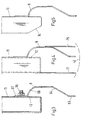
- the column 2 shown in FIG. 1 contains a liquid distributor 1 and a Pack 3.
- a gas 4 flows up the column 2, flows around above the package 3 distributing members 11 of the liquid distributor 1 and is characterized into a plurality of partial streams 40 ', 40 "separated, which subsequently Form part streams 40.
- the distributing members 11 receive one to be distributed Liquid 5 via a supply line 20 and a pre-distributor 10th
- FIG. 2a for a distributor according to the invention 1, the environment of a Outlet opening 12 of a distributor 11 shown as a sectional view.
- the Outlet opening 12 is located in an inclined side wall 13.
- the side wall 13 is vertical; the measured against the vertical 9 Angle ⁇ is thus equal to zero.
- the liquid 5 flows in the direction 15 the opening 12, then forms a free beam 50, the Centerline 50 'is bent downwards following gravity, and hits in Direction 50 "on a arranged in front of the opening 12 screen 6.
- Ein Impact area 60 of the screen 6 is assumed to be just here.
- the Lines 8, 8 'and 8 "indicated by dot-dash lines are parallel, parallel to the plane lying in the impact area 60.
- the angle of incidence ⁇ which is spanned by the lines 50 "and 8 ', is slightly smaller than that Angle ⁇ 'between the straight line 8 "and the outflow direction 15.
- the on the jet 6 impinging liquid jet 50 becomes an effluent Liquid film 51 formed.
- the angle of incidence ⁇ is, the more less is the amount of released droplets 55.
- the screen 6 is connected to a strip-shaped region 61 on the distributor 11 attached in such a way that a passage of gas 4 is prevented and thus the outlet opening 12 of the upwardly flowing gas stream. 4 is shielded.
- the screen 6 sits over a closed guide wall 64 - see Fig. 2b -. to a drip edge 62 on which the liquid film 51 in the form of Drop 53 or continues to drop as a closed film.
- the drip edge 62 is horizontally aligned and may be rectilinear or jagged be.
- the drip edge 62 is located in a storage zone 42 of the gas 4, in which the dripping of the liquid 5 largely undisturbed by the Flow of the gas 4 takes place.
- a strip-shaped portion 63 is provided, which is largely in a vertical Level lies.
- the flat impact angle a also has the consequence that the parabolic Propagation of the liquid film on the screen 6 less of the pulse the liquid jet 50 depends. The difference between one maximum and a minimum parabolic width is therefore smaller. These Fact facilitates the design of distributors.
- Fig. 3 shows a cross section through the lower part of a trough-shaped Distributor 11.
- the shield 6 has in a vertical and beam parallel Cut the shape of a sigmoid curve, i. a curve that a Turning point has its curvature. This curve can be complete or partial be given by a track train.
- the sigmoidal curve is after curved down. It has there, in particular, a largely constant Curvature up.
- the impact area 60 is shaped so that the beam 51 Approximately tangentially impinges on the screen 6.
- the screen 6 is at his upper part 61 is fastened with screws 16.
- Fig. 4 shows a side view of an embodiment in which in Area of the storage zone 42 flanking the umbrella 6 in addition aprons 71st and 76 are provided, with which the gas flow favorably influenced becomes.
- the screen 6 is welded to the distributor 11 (point-welded) or soldered.
- the distributor 11 and the screen 6 are advantageously shaped so that in the surroundings of the storage zone 42, the partial flows 40 ', 40 "- see Figures 1 and 2b - largely mirror-symmetrical to each other and with respect to a vertical plane formed by the drip edge 62. To this, too reach the distributor 11 according to FIG. 5 in a lower area with a wedge-shaped wall piece 14 formed wedge-shaped.
- the screens 6 of the inventive liquid distributor 1 can - like this is illustrated in Fig. 6 - to favorably influence the liquid films 51 each structuring by grooves 640 and / or perforations 630th exhibit.
- the drip edge 62 may be provided with serrations 620.
- Fig. 7 shows another embodiment, in the skirts 76 ', 71' to Influencing the flow are curved.
- the outlet opening 12 is as in Fig. 2a in an inclined part of a side wall 13 of the Distributor 11 is arranged.
- this embodiment forms the Distributor 11 including the screen 6 an obstacle to the top flowing gas, which has a lower flow resistance than the Examples of Figures 3 to 5 is connected.
Landscapes
- Chemical & Material Sciences (AREA)
- Chemical Kinetics & Catalysis (AREA)
- Engineering & Computer Science (AREA)
- Analytical Chemistry (AREA)
- General Chemical & Material Sciences (AREA)
- Oil, Petroleum & Natural Gas (AREA)
- Vaporization, Distillation, Condensation, Sublimation, And Cold Traps (AREA)
- Physical Or Chemical Processes And Apparatus (AREA)
Claims (10)
- Distributeur de liquide (1), en particulier pour des colonnes de garnissage (2), avec au moins un organe de distribution en forme de tube ou d'auge (11) qui, pour une émission du liquide (5) sous forme de jets (50), présente des ouvertures de sortie (12), et avec des écrans (6) disposés devant les ouvertures de sortie, sur lesquels les jets de liquide incidents (50) sont transformés en films de liquide qui s'écoulent (51) et qui protègent les ouvertures de sortie contre un flux de gaz (4) s'écoulant vers le haut, caractérisé en ce que lors d'une émission maximale de liquide, les jets de liquide (50) sur les écrans (6) sont incidents sous des angles (α) qui sont plus petits que 60°, de préférence plus petits que 10°.
- Distributeur de liquide selon la revendication 1, caractérisé en ce que chaque écran (6), en une coupe verticale ainsi que parallèle au jet, a la forme d'une courbe sigmoïde, où cette courbe peut être réalisée aussi entièrement ou partiellement par une section courbée, et en ce que la courbe sigmoïde, dans la zone (60), dans laquelle les jets de liquide (50) frappent l'écran, est courbée avantageusement vers le bas et présente en particulier une courbure sensiblement constante.
- Distributeur de liquide selon la revendication 2, caractérisé en ce que la zone d'incidence (60) est formée de façon que les jets heurtent approximativement tangentiellement les écrans (6).
- Distributeur de liquide selon l'une des revendications 1 à 3, caractérisé en ce que les écrans (6) présentent des arêtes d'égouttage (62), qui sont orientées horizontalement et qui peuvent être rectilignes ou dentées.
- Distributeur de liquide selon la revendication 4, caractérisé en ce que sont prévues directement au-dessus des arêtes d'égouttage (62) des zones en forme de bande (63) qui se situent sensiblement dans des plans verticaux.
- Distributeur de liquide selon l'une des revendications 1 à 5, caractérisé en ce que les écrans (6), pour agir sur les films de liquide (51), présentent à chaque fois une structuration par des rainures (640) et/ou des perforations (630).
- Colonne (2) avec un distributeur de liquide (1) selon l'une des revendications 1 à 6, caractérisée en ce que plusieurs organes de distribution parallèles (11) divisent un flux de gaz (4) remontant dans la colonne dans plusieurs flux partiels (40', 40", 40) de façon que sous les organes de distribution, des zones d'accumulation (42) se forment, et en ce que des arêtes d'égouttage (62) des écrans (6) sont disposées à l'intérieur des zones d'accumulation.
- Colonne selon la revendication 7, caractérisée en ce que les organes de distribution (11) et les écrans (6) sont formés de façon que respectivement dans l'environnement des zones d'accumulation, les flux partiels (40', 40") sont réalisés dans une grande mesure d'une manière spéculairement symétrique et par rapport aux plans verticaux par les arêtes d'égouttage (62).
- Colonne selon la revendication 7 ou 8, caractérisée en ce que pour agir sur l'écoulement (4), additionnellement des tabliers (71', 76') sont prévus au voisinage des zones d'accumulation (42) de manière contiguë aux écrans (6).
- Colonne selon l'une des revendications 7 à 9, caractérisée en ce que le distributeur (1) est disposé au-dessus d'un garnissage (3) qui présente une structure ordonnée, où en particulier le garnissage est un « garnissage à lit fluidisé » ou un garnissage avec une « structure de canaux croisés ».
Priority Applications (1)
| Application Number | Priority Date | Filing Date | Title |
|---|---|---|---|
| EP19990810992 EP1005889B1 (fr) | 1998-11-30 | 1999-11-02 | Distributeur de liquide pour des colonnes garnies |
Applications Claiming Priority (3)
| Application Number | Priority Date | Filing Date | Title |
|---|---|---|---|
| EP98811187 | 1998-11-30 | ||
| EP98811187 | 1998-11-30 | ||
| EP19990810992 EP1005889B1 (fr) | 1998-11-30 | 1999-11-02 | Distributeur de liquide pour des colonnes garnies |
Publications (2)
| Publication Number | Publication Date |
|---|---|
| EP1005889A1 EP1005889A1 (fr) | 2000-06-07 |
| EP1005889B1 true EP1005889B1 (fr) | 2005-03-30 |
Family
ID=26152089
Family Applications (1)
| Application Number | Title | Priority Date | Filing Date |
|---|---|---|---|
| EP19990810992 Expired - Lifetime EP1005889B1 (fr) | 1998-11-30 | 1999-11-02 | Distributeur de liquide pour des colonnes garnies |
Country Status (1)
| Country | Link |
|---|---|
| EP (1) | EP1005889B1 (fr) |
Families Citing this family (3)
| Publication number | Priority date | Publication date | Assignee | Title |
|---|---|---|---|---|
| EP1459793B1 (fr) * | 2003-03-17 | 2011-07-27 | Sulzer Chemtech AG | Distributeur de liquide |
| EP1464370A1 (fr) * | 2003-03-17 | 2004-10-06 | Sulzer Chemtech AG | Distributeur de liquide |
| EP3417923A1 (fr) * | 2017-06-20 | 2018-12-26 | Sulzer Chemtech AG | Distributeur de liquide pour un dispositif de séparation comprenant un écran constitué d'un matériau composite en carbone |
Family Cites Families (4)
| Publication number | Priority date | Publication date | Assignee | Title |
|---|---|---|---|---|
| US4159291A (en) * | 1977-08-16 | 1979-06-26 | Union Carbide Corporation | Outlet means for vapor-liquid contacting tray |
| DE3013783A1 (de) * | 1979-11-08 | 1981-10-15 | Julius Montz Gmbh, 4010 Hilden | Fluessigkeitsverteiler fuer eine gegenstromkolonne |
| CH653909A5 (de) * | 1981-07-30 | 1986-01-31 | Sulzer Ag | Kolonne fuer stoff- und/oder waermeaustauschverfahren. |
| CH671165A5 (fr) * | 1987-03-02 | 1989-08-15 | Sulzer Ag |
-
1999
- 1999-11-02 EP EP19990810992 patent/EP1005889B1/fr not_active Expired - Lifetime
Also Published As
| Publication number | Publication date |
|---|---|
| EP1005889A1 (fr) | 2000-06-07 |
Similar Documents
| Publication | Publication Date | Title |
|---|---|---|
| EP1013324A2 (fr) | Colonne à contre-courant avec distributeur de liquide | |
| DE2810200A1 (de) | Gas-fluessigkeitskontakttraeger mit verbesserter blasenfoerdereinrichtung am einlass | |
| DE69412578T2 (de) | Hochleistungswanne für gas-flüssigkeitskontaktvorrichtung | |
| DE69725289T2 (de) | Verfahren und vorrichtung zur verbesserten dampfverteilung | |
| CH642566A5 (de) | Trogartige vorrichtung zum sammeln und verteilen der fluessigkeit in einer gegenstromkolonne. | |
| DE68926604T2 (de) | Flüssigkeitsverteiler für einen Füllkörperturm | |
| DE2835598A1 (de) | Dampf-fluessigkeits-kontaktboden und damit ausgeruestete dampf-fluessigkeits- kontaktkolonne | |
| EP1005889B1 (fr) | Distributeur de liquide pour des colonnes garnies | |
| DE3529114A1 (de) | Fluessigkeitsverteiler fuer eine stoffaustauschkolonne | |
| DE2312475C3 (de) | Vorrichtung zum Entgasen von Wasser unter Überdruck, insbesondere von Kesselspeisewasser | |
| EP0558873B1 (fr) | Installation de séparation des aérosols de l'air provenant d'une enceinte de réacteur nucléaire | |
| DE2031816C3 (de) | Verfahren zum Abkühlen eines auf einem Draht, Band oder einem anderen Profil ununterbrochener Länge durch Heißtauchmetallisierung abgeschiedenen Überzugs und Vorrichtung zur Durchführung des Verfahrens | |
| EP1755763B1 (fr) | Dispositif separateur de gouttes | |
| DE102004056419A1 (de) | Geordnete Packung für Wärme und/oder Stoffaustausch | |
| DE4237350C2 (de) | Verfahren zum Stoffübertragen sowie Vorrichtung zur Durchführung des Verfahrens | |
| DE2128897A1 (de) | Vorrichtung zum abscheiden von fluessigkeit aus einem grossen gasmengenstrom | |
| EP1317948B1 (fr) | Colonne à plateaux | |
| DE4210133C1 (fr) | ||
| DE2212785B2 (de) | Vorrichtung zur Kühlung von Überzügen auf bewegten Drähten | |
| DE102004018341A1 (de) | Fluid-Zuspeisevorrichtung für eine Kolonne | |
| DE4419129C1 (de) | Verfahren zum Betreiben von Trennkolonnen sowie Trennkolonne zur Durchführung des Verfahrens | |
| EP1153640B1 (fr) | Récipient à déflecteur pour dériver un jet de liquide | |
| DE2916462A1 (de) | Vorrichtung zum verteilen von waschfluessigkeit auf einen mit einbauten versehenen wascher oder abtreiber | |
| EP3009177B1 (fr) | Distributeur de liquide d'une colonne technologique | |
| DD221639A1 (de) | Einspeiszone fuer stoffaustauschkolonnen |
Legal Events
| Date | Code | Title | Description |
|---|---|---|---|
| PUAI | Public reference made under article 153(3) epc to a published international application that has entered the european phase |
Free format text: ORIGINAL CODE: 0009012 |
|
| AK | Designated contracting states |
Kind code of ref document: A1 Designated state(s): AT BE CH CY DE DK ES FI FR GB GR IE IT LI LU MC NL PT SE |
|
| AX | Request for extension of the european patent |
Free format text: AL;LT;LV;MK;RO;SI |
|
| 17P | Request for examination filed |
Effective date: 20001109 |
|
| AKX | Designation fees paid |
Free format text: AT BE CH CY DE DK ES FI FR GB GR IE IT LI LU MC NL PT SE |
|
| GRAP | Despatch of communication of intention to grant a patent |
Free format text: ORIGINAL CODE: EPIDOSNIGR1 |
|
| GRAS | Grant fee paid |
Free format text: ORIGINAL CODE: EPIDOSNIGR3 |
|
| GRAA | (expected) grant |
Free format text: ORIGINAL CODE: 0009210 |
|
| AK | Designated contracting states |
Kind code of ref document: B1 Designated state(s): AT BE CH CY DE DK ES FI FR GB GR IE IT LI LU MC NL PT SE |
|
| PG25 | Lapsed in a contracting state [announced via postgrant information from national office to epo] |
Ref country code: IE Free format text: LAPSE BECAUSE OF FAILURE TO SUBMIT A TRANSLATION OF THE DESCRIPTION OR TO PAY THE FEE WITHIN THE PRESCRIBED TIME-LIMIT Effective date: 20050330 Ref country code: FI Free format text: LAPSE BECAUSE OF FAILURE TO SUBMIT A TRANSLATION OF THE DESCRIPTION OR TO PAY THE FEE WITHIN THE PRESCRIBED TIME-LIMIT Effective date: 20050330 |
|
| REG | Reference to a national code |
Ref country code: GB Ref legal event code: FG4D Free format text: NOT ENGLISH |
|
| REG | Reference to a national code |
Ref country code: CH Ref legal event code: EP |
|
| REG | Reference to a national code |
Ref country code: CH Ref legal event code: NV Representative=s name: SULZER MANAGEMENT AG PATENTABTEILUNG/0067 |
|
| GBT | Gb: translation of ep patent filed (gb section 77(6)(a)/1977) |
Effective date: 20050330 |
|
| REF | Corresponds to: |
Ref document number: 59911838 Country of ref document: DE Date of ref document: 20050504 Kind code of ref document: P |
|
| REG | Reference to a national code |
Ref country code: IE Ref legal event code: FG4D Free format text: LANGUAGE OF EP DOCUMENT: GERMAN |
|
| PG25 | Lapsed in a contracting state [announced via postgrant information from national office to epo] |
Ref country code: GR Free format text: LAPSE BECAUSE OF FAILURE TO SUBMIT A TRANSLATION OF THE DESCRIPTION OR TO PAY THE FEE WITHIN THE PRESCRIBED TIME-LIMIT Effective date: 20050630 Ref country code: DK Free format text: LAPSE BECAUSE OF FAILURE TO SUBMIT A TRANSLATION OF THE DESCRIPTION OR TO PAY THE FEE WITHIN THE PRESCRIBED TIME-LIMIT Effective date: 20050630 |
|
| PG25 | Lapsed in a contracting state [announced via postgrant information from national office to epo] |
Ref country code: PT Free format text: LAPSE BECAUSE OF FAILURE TO SUBMIT A TRANSLATION OF THE DESCRIPTION OR TO PAY THE FEE WITHIN THE PRESCRIBED TIME-LIMIT Effective date: 20050907 |
|
| REG | Reference to a national code |
Ref country code: ES Ref legal event code: FG2A Ref document number: 2241254 Country of ref document: ES Kind code of ref document: T3 |
|
| PG25 | Lapsed in a contracting state [announced via postgrant information from national office to epo] |
Ref country code: CY Free format text: LAPSE BECAUSE OF FAILURE TO SUBMIT A TRANSLATION OF THE DESCRIPTION OR TO PAY THE FEE WITHIN THE PRESCRIBED TIME-LIMIT Effective date: 20051102 Ref country code: AT Free format text: LAPSE BECAUSE OF NON-PAYMENT OF DUE FEES Effective date: 20051102 |
|
| PG25 | Lapsed in a contracting state [announced via postgrant information from national office to epo] |
Ref country code: MC Free format text: LAPSE BECAUSE OF NON-PAYMENT OF DUE FEES Effective date: 20051130 Ref country code: LU Free format text: LAPSE BECAUSE OF NON-PAYMENT OF DUE FEES Effective date: 20051130 Ref country code: BE Free format text: LAPSE BECAUSE OF NON-PAYMENT OF DUE FEES Effective date: 20051130 |
|
| REG | Reference to a national code |
Ref country code: IE Ref legal event code: FD4D |
|
| ET | Fr: translation filed | ||
| PLBE | No opposition filed within time limit |
Free format text: ORIGINAL CODE: 0009261 |
|
| STAA | Information on the status of an ep patent application or granted ep patent |
Free format text: STATUS: NO OPPOSITION FILED WITHIN TIME LIMIT |
|
| 26N | No opposition filed |
Effective date: 20060102 |
|
| BERE | Be: lapsed |
Owner name: SULZER CHEMTECH A.G. Effective date: 20051130 |
|
| PG25 | Lapsed in a contracting state [announced via postgrant information from national office to epo] |
Ref country code: SE Free format text: LAPSE BECAUSE OF FAILURE TO SUBMIT A TRANSLATION OF THE DESCRIPTION OR TO PAY THE FEE WITHIN THE PRESCRIBED TIME-LIMIT Effective date: 20050630 |
|
| REG | Reference to a national code |
Ref country code: CH Ref legal event code: PCOW Free format text: NEW ADDRESS: SULZERALLEE 48, 8404 WINTERTHUR (CH) Ref country code: CH Ref legal event code: NV Representative=s name: DR. GRAF AND PARTNER AG INTELLECTUAL PROPERTY, CH |
|
| REG | Reference to a national code |
Ref country code: FR Ref legal event code: PLFP Year of fee payment: 17 |
|
| PGFP | Annual fee paid to national office [announced via postgrant information from national office to epo] |
Ref country code: CH Payment date: 20151118 Year of fee payment: 17 |
|
| REG | Reference to a national code |
Ref country code: FR Ref legal event code: PLFP Year of fee payment: 18 |
|
| REG | Reference to a national code |
Ref country code: CH Ref legal event code: PL |
|
| PG25 | Lapsed in a contracting state [announced via postgrant information from national office to epo] |
Ref country code: LI Free format text: LAPSE BECAUSE OF NON-PAYMENT OF DUE FEES Effective date: 20161130 Ref country code: CH Free format text: LAPSE BECAUSE OF NON-PAYMENT OF DUE FEES Effective date: 20161130 |
|
| REG | Reference to a national code |
Ref country code: DE Ref legal event code: R082 Ref document number: 59911838 Country of ref document: DE Representative=s name: HENKEL & PARTNER MBB PATENTANWALTSKANZLEI, REC, DE Ref country code: DE Ref legal event code: R082 Ref document number: 59911838 Country of ref document: DE Representative=s name: PATENTANWAELTE HENKEL, BREUER & PARTNER MBB, DE Ref country code: DE Ref legal event code: R082 Ref document number: 59911838 Country of ref document: DE Representative=s name: HENKEL, BREUER & PARTNER, DE Ref country code: DE Ref legal event code: R082 Ref document number: 59911838 Country of ref document: DE Representative=s name: PATENTANWAELTE HENKEL, BREUER & PARTNER, DE Ref country code: FR Ref legal event code: PLFP Year of fee payment: 19 |
|
| REG | Reference to a national code |
Ref country code: DE Ref legal event code: R082 Ref document number: 59911838 Country of ref document: DE Representative=s name: HENKEL & PARTNER MBB PATENTANWALTSKANZLEI, REC, DE Ref country code: DE Ref legal event code: R082 Ref document number: 59911838 Country of ref document: DE Representative=s name: PATENTANWAELTE HENKEL, BREUER & PARTNER MBB, DE Ref country code: DE Ref legal event code: R082 Ref document number: 59911838 Country of ref document: DE Representative=s name: HENKEL, BREUER & PARTNER, DE |
|
| PGFP | Annual fee paid to national office [announced via postgrant information from national office to epo] |
Ref country code: NL Payment date: 20181120 Year of fee payment: 20 |
|
| PGFP | Annual fee paid to national office [announced via postgrant information from national office to epo] |
Ref country code: DE Payment date: 20181120 Year of fee payment: 20 |
|
| PGFP | Annual fee paid to national office [announced via postgrant information from national office to epo] |
Ref country code: ES Payment date: 20181218 Year of fee payment: 20 Ref country code: IT Payment date: 20181126 Year of fee payment: 20 Ref country code: GB Payment date: 20181120 Year of fee payment: 20 Ref country code: FR Payment date: 20181123 Year of fee payment: 20 |
|
| REG | Reference to a national code |
Ref country code: DE Ref legal event code: R082 Ref document number: 59911838 Country of ref document: DE Representative=s name: HENKEL & PARTNER MBB PATENTANWALTSKANZLEI, REC, DE Ref country code: DE Ref legal event code: R082 Ref document number: 59911838 Country of ref document: DE Representative=s name: PATENTANWAELTE HENKEL, BREUER & PARTNER MBB, DE |
|
| REG | Reference to a national code |
Ref country code: DE Ref legal event code: R082 Ref document number: 59911838 Country of ref document: DE Representative=s name: HENKEL & PARTNER MBB PATENTANWALTSKANZLEI, REC, DE Ref country code: DE Ref legal event code: R081 Ref document number: 59911838 Country of ref document: DE Owner name: SULZER MANAGEMENT AG, CH Free format text: FORMER OWNER: SULZER CHEMTECH AG, WINTERTHUR, CH |
|
| REG | Reference to a national code |
Ref country code: DE Ref legal event code: R071 Ref document number: 59911838 Country of ref document: DE |
|
| REG | Reference to a national code |
Ref country code: NL Ref legal event code: MK Effective date: 20191101 |
|
| REG | Reference to a national code |
Ref country code: GB Ref legal event code: PE20 Expiry date: 20191101 |
|
| PG25 | Lapsed in a contracting state [announced via postgrant information from national office to epo] |
Ref country code: GB Free format text: LAPSE BECAUSE OF EXPIRATION OF PROTECTION Effective date: 20191101 |
|
| REG | Reference to a national code |
Ref country code: ES Ref legal event code: FD2A Effective date: 20200806 |
|
| PG25 | Lapsed in a contracting state [announced via postgrant information from national office to epo] |
Ref country code: ES Free format text: LAPSE BECAUSE OF EXPIRATION OF PROTECTION Effective date: 20191103 |