EP1011006A1 - System for making spectacles to order - Google Patents
System for making spectacles to order Download PDFInfo
- Publication number
- EP1011006A1 EP1011006A1 EP98919626A EP98919626A EP1011006A1 EP 1011006 A1 EP1011006 A1 EP 1011006A1 EP 98919626 A EP98919626 A EP 98919626A EP 98919626 A EP98919626 A EP 98919626A EP 1011006 A1 EP1011006 A1 EP 1011006A1
- Authority
- EP
- European Patent Office
- Prior art keywords
- eyeglass
- eyeglasses
- portrait
- image
- function
- Prior art date
- Legal status (The legal status is an assumption and is not a legal conclusion. Google has not performed a legal analysis and makes no representation as to the accuracy of the status listed.)
- Granted
Links
- 238000000034 method Methods 0.000 claims abstract description 170
- 238000013461 design Methods 0.000 claims abstract description 161
- 230000002452 interceptive effect Effects 0.000 claims abstract description 17
- 238000004519 manufacturing process Methods 0.000 claims description 55
- 230000001815 facial effect Effects 0.000 claims description 30
- 238000005259 measurement Methods 0.000 claims description 19
- 238000012545 processing Methods 0.000 claims description 18
- 238000003384 imaging method Methods 0.000 claims description 14
- 230000002829 reductive effect Effects 0.000 claims description 8
- 238000005094 computer simulation Methods 0.000 claims description 6
- 239000003086 colorant Substances 0.000 claims description 5
- 230000000670 limiting effect Effects 0.000 claims description 3
- 230000008569 process Effects 0.000 description 31
- 230000008859 change Effects 0.000 description 25
- 238000005520 cutting process Methods 0.000 description 20
- 238000004088 simulation Methods 0.000 description 19
- 238000010586 diagram Methods 0.000 description 10
- 230000008034 disappearance Effects 0.000 description 9
- 238000005452 bending Methods 0.000 description 8
- 210000001747 pupil Anatomy 0.000 description 6
- 230000000694 effects Effects 0.000 description 5
- 230000004044 response Effects 0.000 description 5
- 230000002146 bilateral effect Effects 0.000 description 4
- 239000004677 Nylon Substances 0.000 description 3
- 238000004364 calculation method Methods 0.000 description 3
- 238000007796 conventional method Methods 0.000 description 3
- 230000003247 decreasing effect Effects 0.000 description 3
- 239000010437 gem Substances 0.000 description 3
- 229920001778 nylon Polymers 0.000 description 3
- 230000009467 reduction Effects 0.000 description 3
- 230000004075 alteration Effects 0.000 description 2
- 238000004458 analytical method Methods 0.000 description 2
- 239000000463 material Substances 0.000 description 2
- 238000003801 milling Methods 0.000 description 2
- 230000003287 optical effect Effects 0.000 description 2
- 239000000700 radioactive tracer Substances 0.000 description 2
- 230000002441 reversible effect Effects 0.000 description 2
- 230000008901 benefit Effects 0.000 description 1
- 238000012790 confirmation Methods 0.000 description 1
- 230000007547 defect Effects 0.000 description 1
- 238000012217 deletion Methods 0.000 description 1
- 230000037430 deletion Effects 0.000 description 1
- 238000012938 design process Methods 0.000 description 1
- 238000011156 evaluation Methods 0.000 description 1
- 210000000887 face Anatomy 0.000 description 1
- 238000007429 general method Methods 0.000 description 1
- 239000011521 glass Substances 0.000 description 1
- 210000003128 head Anatomy 0.000 description 1
- 238000012905 input function Methods 0.000 description 1
- 238000003780 insertion Methods 0.000 description 1
- 230000037431 insertion Effects 0.000 description 1
- 238000007689 inspection Methods 0.000 description 1
- 238000012986 modification Methods 0.000 description 1
- 230000004048 modification Effects 0.000 description 1
- 238000011017 operating method Methods 0.000 description 1
- 230000036961 partial effect Effects 0.000 description 1
- 239000002994 raw material Substances 0.000 description 1
- 229910000679 solder Inorganic materials 0.000 description 1
- 230000003068 static effect Effects 0.000 description 1
- 238000003860 storage Methods 0.000 description 1
- 230000000153 supplemental effect Effects 0.000 description 1
- 230000002194 synthesizing effect Effects 0.000 description 1
- 230000001131 transforming effect Effects 0.000 description 1
Images






Classifications
-
- G—PHYSICS
- G02—OPTICS
- G02C—SPECTACLES; SUNGLASSES OR GOGGLES INSOFAR AS THEY HAVE THE SAME FEATURES AS SPECTACLES; CONTACT LENSES
- G02C13/00—Assembling; Repairing; Cleaning
- G02C13/003—Measuring during assembly or fitting of spectacles
Definitions
- the present invention relates to an eyeglasses made-to-order system for determining an eyeglass design to reflect the preferences of the eyeglasses consumer using a computer-controlled display screen; and the present invention also relates to methods applied to this system: a method for generating synthetic images to overlay portraits and eyeglass frames, a method for determining the positions of the endpieces and bridge of the eyeglasses, and a method for changing the eyeglass frame type.
- the abovementioned conventional method has a greater possibility of attaining an eyeglass design which better suits the facial features of the eyeglass wearer because the characteristics of the facial features are analyzed by computer and a design is generated to fit the facial features.
- a computer mainly performs the procedures for analyzing the characteristics of the facial features and selecting the design to suit the characteristics thereof.
- the analysis of the characteristics of the facial features and the determination of the design to fit those analyzed characteristics is in this method essentially made by the people who created the system software, such as the designers and programmers. Consequently, the designs attained inevitably depend greatly on the sensibility and thinking of the people who created the system software.
- an object of the present invention to provide an eyeglasses made-to-order system, wherein an eyeglass design that better reflects the eyeglass wearer's preferences can be determined and ordered quickly with the operator performing only those procedures thought necessary.
- apparatuses to simulate the wearing of eyeglasses using an imaging function to capture the frontal portrait of a person's head on a computer-controlled display screen and displaying the portrait wearing the eyeglasses by laying the image of the eyeglass frames over the portrait on screen, were known to be used in determining eyeglass designs and so forth before now (Japanese Patent Laid-open No. S63-76581).
- the positions of the endpieces and bridge are a regular design consideration, the designer usually determines these from a functional profile, based mainly on an average model that considers the mean facial width and mean distance between pupils, that the bridge does not strike the nose, and whether there is an optimal position for mounting the temples.
- Eyeglass frames can be generally classified into three categories, based mainly on differences in the structures which hold the lenses: the full-rimmed type, the semi-rimless type, and the three-piece type (also known as the Arimless type).
- the full-rimmed type has the entire perimeter of the lenses enclosed by the rims.
- the semi-rimless type has, as the basic structure, all or part of the upper portion of the lens perimeters enclosed with rim and the lower portion supported with nylon thread.
- the three-piece type does not use rim and has the bridge and temples mounted directly on the lenses.
- the present invention employs the following constitution to achieve the abovementioned objects.
- the eyeglasses made-to-order system relating to the present invention comprises:
- the operator of the abovementioned made-to-order system may be the eyeglass consumer, an employee of the store, or someone else; in effect, anyone who can operate the made-to-order system and determine the eyeglass design in a form which sufficiently reflects the will and preferences of the eyeglass consumer.
- the basic frame designs allow the eyeglass consumer to decide upon eyeglasses with a design he/she desires.
- frame designs are collected as base models for selecting eyeglasses with a design similar to that imagined by the eyeglass consumer (Moreover, when frames with a basic design are desired, the frames may be ordered without any changes to the desired basic frame design.). Consequently, frames of various designs with different design tendencies may be prepared to make it possible to respond to the preferences of a broad range of customers (eyeglass consumers). For example, a plurality of designs matched to the frame types are prepared as basic frame designs for each of the frame types (the three types: rimless, semi-rimless, full-rimmed). Moreover, different designs for a single frame type may also be brought together as basic frame designs.
- a method for designing eyeglasses is to select the lens shape, bridge, endpieces, temples, and so forth for a specific design and assemble these selected eyeglass parts; but this method is difficult for the usual customer who is not a designer.
- a plurality of types of basic frame designs is prepared in advance and frames with a design similar to that imagined by the eyeglass consumer are selected from among these basic frame designs as the starting point for determining the design.
- original eyeglasses can be designed with great freedom by making the various preferred changes, including changes to the frame type, to the structural members of the eyeglasses. For this reason, even a regular customer can easily create eyeglasses with the desired design; also, an eyeglass design which better reflects customer preferences can be determined quickly by performing only those procedures thought necessary by the operator.
- the abovementioned changes to the structural members of the eyeglasses include revision, addition and deletion of the structural members.
- Specific examples of changes include changing the frame type, replacing the lens shape, revising the lens shape, changing parts, adding and deleting parts, changing part positions, changing sizes such as eye size and the distance between lenses, changing the colors of the frame parts, changing lens color, changing the lens prescription, and so forth.
- the design is considered in the changes to the abovementioned structural elements; moreover, it is preferable that limiting conditions of the structure, function, and manufacturing requirements be determined and the changes be confirmed to be within a range satisfying these conditions. Thereupon, the specifications for eyeglasses with the desired design are determined and the eyeglass order is placed. After that, cases such as the eyeglasses being impossible to manufacture due to structural reasons, or the like, will not arise and the process can immediately advance to the manufacture of the eyeglasses.
- the eyeglasses made-to-order system relating to the present invention comprises:
- the eyeglasses made-to-order system is a system wherein the abovementioned synthetic image generating function comprises the function of laying the profile image of the selected frames over the profile image of the eyeglass consumer's face captured with the abovementioned portrait capturing function, as well as the function of laying the frontal image of the selected frames over the frontal image of the eyeglass consumer's face captured with the abovementioned portrait capturing function.
- the frontal portrait wearing the eyeglass frames shows only the influence of the front portion of the eyeglass frames on the eyeglass wearer.
- the profile portrait wearing the eyeglass frames is important for confirming the design of the eyeglass frames.
- the design of the eyeglass frame is greatly changed by ornamentation, jewels, and so forth applied on the endpieces and temples; and the design greatly influences the profile image of the eyeglass wearer.
- changing the position of the temples (height) and changing the proportional division of the profile with the temples can have effects such as making a short face look longer or a long face look shorter.
- This also allows the wearing of the prescription lenses and frames to be checked from many angles. Consequently, seeing the image of the profile portrait wearing the eyeglass frames makes it possible to select and decide upon the overall details of the design, in determining the design of the eyeglass frames.
- the eyeglasses made-to-order system is a system wherein the abovementioned one or more changing functions include one or more of the following: frame type changing function, lens shape replacing function, lens shape revising function, part changing function, part position changing function, size changing function for changing sizes such as eye size and the distance between lenses, color changing function for changing the colors of the parts constituting the frames, lens color changing function, usage scene changing function for changing the background for lens usage, and lens prescription inputting function.
- the eyeglasses made-to-order system comprises the function of taking facial measurements of the abovementioned eyeglass consumer, adding those measured values, and revising the eyeglass specifications.
- the portrait of the eyeglass consumer wearing the eyeglasses displayed on the display screen is an image of a two-dimensional simulation, not a three-dimensional simulation. Moreover, only approximate numerical values can be attained for the dimensions and angles of various portions of the face such as the facial width and distance between the pupils. For this reason, precise numerical data, relating to the three-dimensional dimensions and angles of each portion of the face to wear the eyeglasses, are necessary in order to produce eyeglass frames which fit the face well.
- the present invention includes a function for adding facial measurements from the eyeglass consumer and revising the eyeglass specifications.
- facial measurements may be made using various measuring instruments, but a specialized face measuring instrument (Japanese Utility Model Laid-open No. S63-110355, Japanese Patent Application No. H9-306003), called a face measure, may be used to make the measurement quickly and precisely.
- This face measuring instrument comprises the structural members of eyeglasses, such as lenses, pads, endpieces, temples, and so forth and is worn on the face in the same way as eyeglasses.
- the dimensions of and angles between the structural members are adjusted to the form of the face.
- the three-dimensional facial form is measured by reading the dimensions of the structural members and the assembled angles between the structural members from the gradations and so forth on the adjusted face measuring instrument.
- the eyeglasses made-to-order system comprises an order check access function for accessing the order check database comprising data including data necessary for manufacturing the eyeglasses after said eyeglass specifications are determined, and attaining information necessary when ordering eyeglasses, including whether it is possible to manufacturing eyeglasses to those specifications, price, or delivery date.
- the eyeglasses made-to-order system comprises an order access function for accessing an order acceptance database, comprising data including order acceptance processing, processing of data necessary for manufacturing the ordered eyeglasses, and processing of instructions necessary for manufacturing the eyeglasses, and completing the order after the abovementioned order check access function is performed and the order determined.
- a method for generating synthetic images for an apparatus to simulate eyeglass wearing relating to the present invention comprises:
- the face of a person seen from the front is not bilaterally symmetric; it is therefore often the case that the frames cannot be placed on the face in a natural position, as when eyeglasses are actually worn on the face, simply by laying the center of the frame image over the center of the line between the corneal vertexes on the display screen.
- An apparently natural overlay of the eyeglass frame image can be attained by determining the reference points on the portrait captured on the display screen with the actual measurements relative to the positions of the person's eyes, and matching the reference points of the eyeglass frame image to the reference points of the portrait.
- the method for generating synthetic images for an apparatus to simulate eyeglass wearing is a method wherein measured values of the distances from the bridge of the abovementioned person's nose to each of the corneal vertexes are used as the actual measurements relative to the placement of the eyes;
- the method for generating synthetic images for an apparatus to simulate eyeglass wearing is a method wherein the frame image is enlarged or reduced relative to the portrait or the portrait is enlarged or reduced relative to the frame image, according to the ratio of the measured values of the distances to the corneal vertexes of the abovementioned person to the distances to the corneal vertexes of the portrait captured on the screen.
- the magnification of the portrait can be conformed to the magnification of the frame image.
- the method for generating synthetic images for an apparatus to simulate eyeglass wearing is a method wherein the portrait is automatically rotated and corrected so that the line segment connecting the corneal vertexes of both eyes of the portrait captured on screen becomes horizontal on the screen.
- the portrait can be automatically made vertical even if the portrait was tilted at the moment when captured on screen.
- the method for generating synthetic images for an apparatus to simulate eyeglass wearing is a method wherein the portrait is revised after the abovementioned automatic rotation and revision using manual rotation so that the entire portrait is balanced.
- the attitude of the portrait can be revised with consideration of the overall balance of the portrait and a natural state of wearing eyeglasses can be simulated.
- the method for generating synthetic images for an apparatus to simulate eyeglass wearing relating to the present invention comprises:
- An image simulating the wearing of the eyeglasses as seen from the side can thereby be attained; this can provide sufficient and accurate information for selecting eyeglasses and can broaden the range of comparing and examining, even in the case of manufacturing custom-made frames. For example, it is possible to confirm effects such as the influence on the eyeglass wearer's profile from adding ornamentation or jewels to the endpieces and temples, or making the face appear longer or shorter by changing temple height and the proportional division of the profile by the temples. It is also possible to confirm the prescription lenses and frames, as worn, from a greater number of directions.
- the reference points for the abovementioned profile image are points to be the reference for appropriately positioning the frames on the profile portrait;
- the reference points are points such as the following: the corneal vertexes, bending point (point of contact with ear), the eye points at a prescribed distance (12 mm, for example) to the front of the corneal vertexes on a line between the corneal vertexes and the bending point, the temple disappearance point which is the boundary point where the temple is hidden by hair beside the face, such as sideburns.
- the temple is placed on a line between the endpiece position and bending point; when there is a temple disappearance point, the end of the temple beyond the temple disappearance point is deleted from the image.
- the method for generating synthetic images for an apparatus to simulate eyeglass wearing comprises the steps of capturing the profile portrait of the abovementioned person's face on a screen, finding the eye points at a position a prescribed distance to the front of the corneal vertexes in the portrait image, and laying the lens profile image using the eye points as reference points, as well as the frame profile image over the lens profile image.
- a method for determining the positions of the endpiece and bridge of the eyeglasses relating to the present invention comprises:
- the method for determining the positions of the endpieces and bridge of the eyeglasses is a method wherein the range of movement for the abovementioned endpieces and bridge is determined from limits of the design or of the function and structure.
- the method for determining the allowable range of movement is to establish reference points and reference lines to establish the maximum and minimum lengths of the endpieces and bridge required by the limitations of the design or of the function and structure, for example, and to determine whether these reference points and reference lines lie within or without the lens shape.
- the method for determining the positions of the endpieces and bridge of the eyeglasses is a method wherein the movements of the abovementioned endpieces and bridge to be moved are linked together.
- the method for determining the positions of the endpieces and bridge of the eyeglasses is a method wherein the direction in which the abovementioned endpieces are moved is limited to a horizontal direction and so that the amounts of movement become the same but in mutually opposite directions for the right eye and the left eye.
- the bilateral symmetry of the eyeglasses is preserved with this type of movement.
- the method for determining the positions of the endpieces and bridge of the eyeglasses is a method wherein the direction in which the abovementioned bridge is moved is limited to a vertical direction.
- the bilateral symmetry of the eyeglasses is preserved with this type of movement.
- a method for changing the type of eyeglass frames relating to the present invention comprises:
- this method for changing the eyeglass frame type it is possible and relatively simple to change the frame type without changing the design image, by performing standard data revision operations and data addition operations for data relating to the eyeglass frames before the change. Accordingly, for example, if this method is performed using the simulation apparatus located in the store, it becomes possible to actually order other types of frames with the design images of frames stocked in the eyeglasses store and to respond to a greater diversity of needs.
- the method for changing the type of eyeglass frames is a method wherein the abovementioned data revision operations for changing from the abovementioned first type of rimless eyeglass frames to the abovementioned second type of full-rimmed eyeglass frames include:
- the method for changing the type of eyeglass frames is a method wherein the abovementioned data revision operations for changing from the abovementioned first type of rimless eyeglass frames to the abovementioned second type of semi-rimless eyeglass frames include:
- the method for changing the type of eyeglass frames is a method wherein the abovementioned data revision operations for changing from the abovementioned first type of semi-rimless eyeglass frames to the abovementioned second type of full-rimmed eyeglass frames include:
- the method for changing the type of eyeglass frames is a method wherein the abovementioned data revision operations and data addition operations are performed with computer simulation methods.
- the method for changing the type of eyeglass frames is a method wherein an image of the eyeglasses won on the face is generated and displayed on a display screen, by capturing a face image of the eyeglass consumer and laying an eyeglass frame image, according to data relating to said eyeglass frames, over the face image;
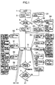
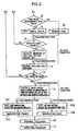
- Figures 1 and 2 are flow charts showing an outline of the eyeglasses made-to-order system relating to the embodiments of the present invention.
- Figures 3 through 9 are diagrams showing examples of the screens used in the made-to-order system relating to the embodiments.
- Figure 10 is a block diagram showing an outline of the hardware comprising the made-to-order system relating to the embodiments. Below, the eyeglasses made-to-order system relating to the embodiments is explained with reference to these figures.
- the hardware for the made-to-order system in the present embodiment comprises a point-of-purchase interactive system 100, a host computer 110 connected by telecommunications lines to this point-of-purchase interactive system 100, and terminal devices 121, 122 in the manufacturing plant connected by telecommunications lines to this host computer 110.
- the point-of-purchase interactive system 100 is principally a computer apparatus comprising a computer 101, an output apparatus such as a display screen (monitor) 101a, and an input apparatus such as a keyboard 101b or mouse 101c.
- the point-of-purchase interactive system may further include a portrait imaging apparatus 102 comprising a digital camera or CCD camera for inputting portrait images to the computer apparatus, and a lens shape measuring instrument (three-dimensional frame tracer (3DFT)) 103 for measuring the lens shapes of the frames selected by the consumer and inputting the measurements to the computer apparatus.
- the operator of this point-of-purchase interactive system 100 may be either an employee of the eyeglass shop or an eyeglass purchaser.
- Program software is installed on the computer 101.
- the operator selects any of the frames representing a plurality of basic designs, prepared in advance and displayed on the abovementioned display screen 101a; then, based on the basic design of the selected frames, the operator can decide upon, and order from the screen, the optimum eyeglass specifications, according to the consumer's preferences, by changing various elements constituting the eyeglasses, such as the various frame types, lens shapes, and parts.
- a summary of the functions of this stored software is as follows.
- the system in this embodiment is characterized by allowing the operator to perform only those procedures or functions thought necessary after selecting the basic frame design, and allowing prompt and accurate ordering of the design best representing the will of the eyeglass consumer.
- the abovementioned synthetic image generating function further includes the function of overlaying the side image of the selected frames on the profile image of the eyeglass consumer's face captured with the abovementioned portrait capturing function. It is thereby possible to confirm the profile portrait with the eyeglass frames in use, as well as the frontal portrait with the eyeglass frames in use; this makes possible the judgement and selection of a comprehensive design in determining the eyeglass frames.
- the abovementioned one or more changing functions may include one or more of the following: frame type changing function, lens shape replacing function, lens shape revising function, part changing function, size changing function for changing sizes such as eye size and the distance between the lenses, color changing function for changing the colors of the frame parts, lens color changing function, usage scene changing function for changing the background of lens use, or lens prescription input function.
- Another function is one wherein, after the abovementioned comparing/examining function is performed and the principal eyeglass specifications and image are determined, facial measurements are made using the face measuring instrument 104 and those measured values are added and the eyeglass specifications are revised.
- the eyeglass frame data are revised based on the relative positions of each part of the eyeglasses determined according to the simulation image and the facial measurement values attained. In this way, appropriate revisions based on precise three-dimensional data of the face according to facial measurements are added to the eyeglass specifications determined with a two-dimensional simulation displayed on the display screen 101a. This makes it possible to attain optimal eyeglass specifications which can be used as manufacturing data for manufacturing eyeglasses to fit the face.
- the face measuring instrument 104 comprises parts corresponding to the parts comprising eyeglasses as shown in Figure 36, for example.
- the face measuring instrument therefore comprises temple portions and a front portion comprising lenses showing the horizontal reference line 141 connecting the frame centers of both lenses, lens frames, pad portions, bridge portion, and endpiece portions.
- the length of each of these parts and the relative positions and angles between the parts can be adjusted; these lengths and relative positions and angles are displayed by graduations or the like and can be measured.
- the face measuring instrument 104 in Figure 36 comprises a lens position information display portion 142, front information display portion 143, and temple information display portion 144.
- a bridge information display portion 145 and pad information display portion 146 are established on the front information display portion 143.
- the program software stored in the abovementioned computer 101 also has an order check access function for accessing the order check database comprising data, including data necessary for eyeglass manufacturing, after the eyeglass specifications are determined and getting the information necessary when the eyeglasses are ordered including the delivery data and the possibility and cost of manufacturing eyeglasses to those specifications.
- the abovementioned software also has an order access function for accessing the order database comprising data including order processing, data processing necessary for manufacturing the ordered eyeglasses, and instruction processing necessary for eyeglass manufacturing, and completing the order after the order check access function is performed and the order is determined.
- order check database and order database are stored in the host computer 110.
- the host computer 110 In addition to the order check database and the order database, the host computer 110 also has the function of generating a work order based on the order data and sending the data necessary for manufacturing the frames and lenses to the terminal apparatuses 121 and 122 in the manufacturing plant.
- the eyeglasses made-to-order system is started through the keyboard 101b or mouse 101c of the interactive system 100 (step 1).
- the display screen then shows the opening screen, as shown in Figure 3.
- a slide show screen for showing an overview of the eyeglasses made-to-order system, can be selected; a screen saver can also be turned on as necessary.
- the operation to advance to the next step is performed through the keyboard 101b or mouse 101c. This operation is carried out by clicking a prescribed location on the screen with the mouse 101c or by operating a prescribed key on the keyboard 101b. Moreover, in the following explanation, the same types of operations are performed when advancing to the next step.
- the display screen Upon advancing to the next step from the abovementioned opening screen, the display screen becomes the screen for selecting the basic design, as shown in Figure 4 (step 2).
- This step is the step for selecting the frames to form the basis for the design.
- the operator selects the preferred frame image, from among a plurality of frame images of basic designs previously stored in the computer.
- frames to form the basis for the design frames with a plurality of designs are established for each frame type (rimless, semi-rimless, or full-rimmed, etc.) and are displayed on the screen.
- the frame images include side views as well as frontal views, so that the overall design can be more precisely grasped.
- the basic frame designs are not prepared in advance so that the operator has to make a final selection from among these prepared designs.
- step 3 Upon the selection of the basic frame design in the abovementioned step 2, the process advances to the next step, portrait capturing (step 3). Moreover, the order of steps 1 and 2 may be reversed. Step 3 can be omitted with a pass operation when the operator decides it is not necessary and the process advanced to the next step for displaying and outputting the frames only (step 4).
- a frontal image of the face is imaged with the portrait imaging apparatus 102 and that image is captured by the computer (step 31).
- the operator selects whether to have a profile image made (step 32).
- a profile image is made (step 34) and the overlap, laying the abovementioned selected frames on the frontal image and profile image, is performed by the computer (step 35).
- the overlap, laying the abovementioned selected frames on the abovementioned frontal image is performed by the computer (step 33).
- Figure 5 shows the screen displaying the portrait captured by imaging.
- Figure 6 shows the screen for the overlap process.
- the PD pupil distance values which are the positions of corneal vertexes, distance between corneal vertexes, and distance between pupils, are input from the screen.
- OBS point ear contact point
- the temple disappearance point which is the point where the temple disappears into the hair
- the frame size is adjusted and input with consideration given to the design of the selected frames, the size of the face in the portrait, the power of the mounted lenses, and so forth.
- the portrait is rotated on the screen and corrected as necessary; this makes for a more natural face image and allows the consumer to make a more appropriate evaluation.
- the synthetic image generating method for overlaying the frame image on the portrait image in steps 33 and 35 for the abovementioned overlap, is explained in further detail using Figures 11 through 16.
- the synthetic image generating method explained using Figures 11 through 16 can be used as a synthetic image generating method in an eyeglass wearing simulation apparatus, in a usual design process or the like, as well as for the eyeglasses made-to-order system in the present embodiment.
- This method can also be used in the case of overlaying an image of an existing eyeglass frame on a portrait image on the screen and showing the portrait wearing the eyeglasses.
- the simulation apparatus applying this synthetic image generating method comprises a display for displaying the screens, a database storing eyeglass frame information, a computer including various input devices, and a camera for imaging the face and left and right profiles of a person and inputting the static image data to the computer.
- the computer can fetch the portrait for the person imaged with the camera to the display screen, while reading the necessary frame image information from the database, and overlaying the frame information on the portrait on screen while applying appropriate revisions.
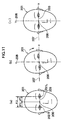
- the center of the bridge of the nose (center of the pupilometer pad position) of the frontal portrait 201 on screen is found as a reference point 206 as shown in Figure 11; meanwhile, the portrait 201 is rotated and returned to a correct position.
- the coordinates of the corneal vertexes 202L and 202R for the right and left eyes in the portrait 201 are found by clicking on the image; a line segment (below Aline between corneal vertexes) 203 connecting the corneal vertexes 202L, 202R is drawn.
- this method uses the ratio between the actual corneal vertex distances of both eyes, measured using a pupilometer in the previous prescription preparing stage, in effect the measured values LPD, RPD (known values) of the distances from the nose position (bridge of nose) to each of the corneal vertexes (corresponding to center of pupils).
- the line between corneal vertexes 203 on the abovementioned portrait 201 is divided proportionally using that ratio; the point of division is the reference point 206 for eyeglasses worn on the portrait 201.
- the display magnification of the frames is one
- the magnification of the portrait is also set to one
- the percentage of reduction or enlargement is stored temporarily because it is also used for the reduction or enlargement of the profile image.
- the magnification of the frame display may also be adjusted to the portrait magnification, because it is good for the frame display magnification to match the portrait magnification.
- the horizontal reference line (X axis) 207 and vertical reference line (Y axis) 208 on the screen are then displayed as supplementary lines passing through the reference point 206 of the portrait 201 as shown in Figure 11 (b).
- the reference lines for indicating the relative positions, are included in order for making adjustments to the inclination of the face.
- the portrait 201 is rotated around the reference point 206, based on means for rotating the portrait with an automated operation, so that the line between corneal vertexes 203 matches the horizontal reference line 207. The processing of the portrait 201 is thereby completed.
- the eyeglass frame image 210 illustrated in Figure 12 comprises the lenses 211, bridge 212, pads 213, endpieces 214, temple 215, and so forth.
- the point of intersection of the horizontal line (datum line) 217, connecting the geometrical centers (centroids) of the forms of the right and left lenses 211, and the vertical line (frame center line) 218, passing through the center of the bridge 212, is established as the reference point 216 for the frames 210.
- the portrait is overlain with the eyeglass frame image.
- the frame design preferred by the consumer is selected from among various types of frame designs and the position at which the frames are placed on the portrait is established.
- placing the frame image 210 at this position produces an image simulating eyeglass wearing, with consideration of the lack of bilateral symmetry of the portrait.
- means for moving the frame image can be used to make slight adjustments to the rotation of the portrait 201 and to correct the vertical position of the frame image 210.
- FIG 14 (a) there may be an inclination of the overall balance of the portrait 201 (for example, when the eyes are not horizontal with respect to the entire face), when the line between corneal vertexes 203 of the portrait 201 is matched by automatic rotation to the horizontal reference line 207 on the screen.
- the portrait 201 is again corrected by manual rotation around the reference point 206 so that the frames are placed horizontally and so that the overall portrait is balanced after automatic rotation and revision as shown in Figure 14 (b).
- the reference point 216 of the frame image is established as shown in Figure 15 (a) and the frame image 210 overlaid as shown in Figure 15 (b).
- the positions are adjusted and corrected by rotating (automatically and manually) the portrait without rotating the frames. For this reason, rotary calculations become unnecessary in any subsequent calculations for transforming the frames and the amount of operations can be reduced.
- the previously captured profile portrait 201S is reduced or enlarged according to the magnification used to enlarge or reduce the frontal portrait discussed above.
- the corneal vertex 221 and bending point (point where the temple bends around the ear) 227 of the profile portrait 201S are isolated.
- the points 221 and 227 are connected by a line 222.
- the central axis of the frames (or FC axis) 226 is established parallel to and 3 mm (value determined from the lens prescription including the lens form) downward from the line 222 connecting the corneal vertex 221 and the bending point 227.
- the FC axis 226 is a line normal to the front surface of the frame (reference surface established to include both lens shapes) and which passes through the geometrical centers (centroids) of both lens shapes.
- the lens cross sectional image 225A is rotated around the eye point 223 so that this FC axis 226 is inclined at a prescribed angle (preferably 3 to 8° , and more preferably 5° ) to the line 222, and the lens cross sectional image 225B is attained.
- the lens profile image 225C corresponding to this inclined lens cross sectional image 225B, is displayed as shown in Figure 16 (b). The synthesized image with the prescription lens actually positioned before the eye is thereby attained.
- the fixed endpiece position 228 extracted from the frontal frame image is reflected and plotted on the lens profile image 225C.
- the fixed endpiece position 228 and bending point 227 are connected with a line 229 and the frame profile image is laid over that line 229 so that the temple matches that line 229.
- An image simulating the profile view is thereby attained.
- this temple disappearance point 231 which is the boundary point where the temple disappears into the hair 230 on the side of the face as shown in Figure 16 (b)
- this temple disappearance point 231 is extracted and the temple portion toward the end is deleted from the temple disappearance point 231.
- the temple disappearance processing may use the boundary line of the hair instead of the temple disappearance point.
- measured values of the distances of the right and left corneal vertexes from the nose position are used for determining the portrait reference points.
- the reference points for the portrait may also be established using other measured values (for example, distance from the right and left ear positions).
- step 5 the process advances to the next trial step (step 5).
- the trial step (step 5) is the step for selecting one of the following: to advance to one of the steps (steps 50 to 59, ⁇ 1 ⁇ to ⁇ 10 ⁇ in Figures 7 and 8) for the one or more change operations for changing, revising, or inputting necessary items on screen for each of the plurality of structural members of the eyeglasses including various frame types, lens shapes, and parts, based on the frames with the basic design selected in the abovementioned basic design selection step (step 2); or the step to omit these steps and advance to the comparing/examining step (step 6) for deciding whether to use the frames without changes to the selected basic design.
- Step 50 is the step for changing the frame type. This step is executed when the operator wants to change the type (frame type) of frames with the basic design selected in step 2. For example, in the case where the type of frames selected in step 2 is the rimless frame (also called Athree-piece frame), the operator can change to another type of frame (semi-rimless or full rimmed), while retaining the basic design when the consumer does not like the frames when those frames are placed on the screen in the overlap step. In some cases, it is not possible to make this change to another type because of structural aspects and so forth of the frame design; the denial of the change is determined automatically and the items which make necessary the change denial are displayed.
- the type of frames selected in step 2 is the rimless frame (also called Athree-piece frame)
- the operator can change to another type of frame (semi-rimless or full rimmed), while retaining the basic design when the consumer does not like the frames when those frames are placed on the screen in the overlap step.
- This method for changing eyeglass frame type is a method which can change the type of frames without changing the design image.
- the method for changing the eyeglass frame type explained using Figures 18 through 26 can be used in the case of generating design and manufacturing data when changing the frame type for existing eyeglass frames, for example, in the usual process for eyeglass design and manufacturing, as well as in the eyeglasses made-to-order system in the present embodiment.
- Figure 18 is a flow chart of the method for changing frame type relating to the first embodiment.
- Figures 19 through 24 are figures for explaining how to examine and decide upon changes in the process for changing frame type in the first embodiment.
- the method for changing frame type, relating to the first embodiment is explained below with reference to these figures.
- the first embodiment shows an example of the case of changing to a full-rimmed type without changing the design of the three-piece type of frame.
- this first embodiment shows the method of using computer simulations with the display screen for performing the operation of revising data relating to the three-piece frame, such as lens shape data, and the operation for adding data relating to parts of the full-rimmed type of frame that are not in the three-piece type of frame.
- an image of the eyeglasses worn on the face can be displayed by capturing an image of the eyeglass consumer's face and overlaying the eyeglass frame image generated by the data relating to the abovementioned eyeglass frame on the face image.
- the hardware such as the computer used for the simulation, is the same as the constitution discussed above and an explanation thereof is omitted.
- data relating to the frame including the lens shape data for the three-piece frame
- the computer receives data relating to the image of the eyeglass consumer's face from the computer (step 301).
- data relating to the image of the eyeglass consumer's face is input to the computer using a digital camera or the like, an image is synthesized using the input data and the previously input data relating to the frame.
- an image of a face wearing the three-piece frames is displayed on the display screen.
- the screen is changed to a screen showing only the lens shape for the three-piece type of frames; a concave check is performed to check for the presence of concave (step 302).
- Concave means that the curve marking the outline of the lens perimeter is a curve which is convex towards the center of the lens (concavity in the outer edge of the lens), as shown in the three-piece frame lens shape shown in Figure 20.
- the entire design image changes when corrected to the full-rimed type of shape; the change is therefore not possible (step 310).
- the shape of the rim at the lens supporting structure cannot be in the concave shape.
- step 302 When it is confirmed in the abovementioned step 302 that there is no concave, the process advances to the next step 303 and the maximum radius check is performed.
- maximum radius is defined as the maximum radius of curvature R (for example, 150 mm) at which this lens deviation does not occur.
- portions of the three-piece frame lens shape exceed the maximum radius (150 mm, for example) in the maximum radius check (for example, when there are portions which are nearly straight lines), the design image changes greatly when those portions are revised to the maximum radius; in this case as well, the change is not possible (step 311).
- the process advances to the next step 304 and the closing block position is determined.
- a determining closing block shape formed of the trapezoid shown by the solid lines in Figure 21 (1), is used in order to judge whether the closing block is within a range satisfying conditions of the function and structure, and for manufacturing.
- the closing block 321 used for making the decision has the form as shown in Figure 21 (2).
- a blank with a horizontal width of 5 mm (cut from a deformed wire) is used as the raw material; the approximate form of the closing block is made by cutting the rim mounting side of this blank at an angle to match the form of the rim (edge of lens).
- the closing block 321 is divided in two, an upper piece 322 and a lower piece 323; the upper piece 322 and lower piece 323 are soldered to the upper and lower rims 324, 324 respectively.
- a structure wherein the lens is supported by the tension of the rim 324 is created by screwing together the upper piece 322 and lower piece 323 with the screw 326.
- the closing block 321 is hidden behind the rear of the endpiece 325 so it cannot be seen from the front or side of the eyeglasses.
- the length (4.15 mm) of the lower edge (measure line) S1 of the determining closing block form is the sum of the thickness (1.15 mm) of the rim 324, the distance (0.6 mm) from the rim 324 to the screw head of the screw 326, the diameter (1.8 mm) of the screw head, and the distance from the screw head to the end of the closing block.
- This length of the lower edge S1 is the minimum dimension in which the rim and screw can be structurally established in the closing block.
- the lower edge S1 and upper edge (measure line) S2 of the determining closing block form are parallel; the distance (height) between the lower edge S1 and upper edge S2, 2.8 mm, is the minimum dimension for ensuring the solder strength and screw holding strength.
- the end point on the rim mounting side of the lower edge S1 of the determining closing block form is the reference point A1; the end point of the upper edge S2 on the side opposite from the rim mounting side is the reference point A2.
- the end surface of the closing block on the rim mounting side is cut to match the form of the rim.
- the upper edge S2 of the determining closing block form is 5 mm maximum. Consequently, the allowable cutting angle on the rim mounting side (angle formed by the lower edge S1 and the end surface of the rim mounting side) is maximized when the upper edge S2 is 5 mm and the maximum angle max becomes 107° .
- the minimum allowable cutting angle is formed when the upper edge S2 is the shortest distance which still ensures the strength of the screw portion; the minimum angle min becomes 80° .
- the maximum allowable cutting angle max can be increased if the blank size is greater than 5 mm, but the range of possible locations of the closing block can be broadened by using an closing block or determining closing block form which is as small as possible.
- the measure line (lower edge) S1 of the determining closing block form is laid over the lower edge S3 of the endpiece.
- the end point (reference point A1) of the measure line S1 on the rim side is matched with the reference point A3 which is the intersection of the lower edge S3 of the endpiece and the inner line of the rim (outline of the inside of the rim).
- the intersection C1 of the measure line S2 and the inner line of the rim is found and the measure line S5, which is a line connecting this intersection C1 and the reference point A3, is found.
- the angle formed by this measure line S5 and the lower edge S3 of the endpiece is the closing block cutting angle .
- This measure line S5 is used because the actual inner line of the rim (outline of lens shape) is a curve having various radii of curvature and it is difficult to determine the closing block position relative to the curve; the cutting angle is therefore found using the straight measure line S5.
- the closing block can be located at the position shown in the figure; the position of the closing block is determined from the endpiece without the closing block extending beyond the outside of the endpiece.
- the closing block cutting line (cutting surface) cannot be matched to the inner line of the rim, even when the measure line S1 of the determining closing block form is positioned over the lower edge S3 of the endpiece (setting position P1).
- the reference point A1 of the determining closing block form is rotated around the reference point A3 to match the closing block cutting line to the inner line of the rim.
- the range in which this type of rotation is possible is as shown in Figure 22.
- the determining closing block form is rotated by angle to the rotation position (setting position) P2 where the reference point A2 matches the upper edge S4 of the endpiece. If rotated further, the closing block extends beyond the endpiece.
- the closing block cannot be established on the endpiece side; the setting position for the closing block is established on the bridge side (nose side).
- the lower edge S3 and upper edge S4 which are the outer lines of the endpiece shown with straight lines, represent the minimum shape which can effectively hid the closing block.
- a curved ornament or the like is sometimes formed father to the outside of the edges S3, S4.
- step 304 the process advances to step 305 and an radius check for the closing block position is performed.
- This radius check for the closing block position determines whether the radius R of the rim curvature at the position where the closing block is mounted is greater than the minimum radius R of curvature (minimum R value) allowable in the closing block cutting work; this radius check also determines the working, tools used and the working conditions.
- the process advances to step 307 if it is determined that the R value is greater than the minimum allowable radius of curvature for the closing block cutting work.
- step 305 When it is determined that the R value is less than the minimum allowable radius of curvature for the closing block cutting work in the abovementioned step 305, the radius of curvature of the closing block mounting position is corrected to the minimum allowable radius of curvature for the closing block cutting work (minimum R value) in step 306 and the process advances to step 307.
- a minimum radius check is performed.
- the rim is formed from rim wound in a specified form by a rim winder. At that time, the rim is wound by a cam provided in the rim winder; the radius R of curvature of the rim, for manufacturing, is not attained if the minimum R value is less than the radius of curvature of that cam. Consequently, in the present embodiment, the minimum radius of curvature to allow manufacturing is the minimum radius.
- the process advances to step 308 and those portions are corrected to the minimum radius.
- step 308 the design image does not change significantly in this case even when the revisions are made, therefore the revisions are possible.
- the process advances to step 309, data for a full-rimmed frame having the same design image as that of the three-piece frame before the changes is attained, and the changes to the frame type are complete.
- the abovementioned first embodiment makes it possible to change the frame type with relative simplicity without changing the design image, by following prescribed procedures, while using the data relating to the frames before the changes. If this method is performed using a simulation apparatus comprising a personal computer established at the point of purchase, it becomes possible to order types of frames with design images other than those displayed at the eyeglass shop; this makes it possible to meet more diverse needs.
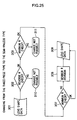
- Figure 25 is a flow chart showing the method for changing frame type relating to the second embodiment.
- This second embodiment shows an example of changing from a three-piece type to a semi-rimless type.
- the process flow is entirely the same as the process flow in the first embodiment shown in Figure 18, except for the steps relating to the closing block, because there is no closing block in the case of the semi-rimless type of frames. Consequently, the same step numbers are used for the steps in the flow chart for the second embodiment in Figure 25 which are the same as those in the first embodiment and an explanation thereof is omitted.
- Figure 26 is a flow chart showing the method for changing frame type relating to the third embodiment.
- This embodiment is an example of changing from the semi-rimless type to the full-rimmed type.
- the process flow is exactly the same as that of the first embodiment in Figure 18, except for the steps relating to concave and minimum radius, because the semi-rimless type has no concave or smallest radius and it is not necessary to determine these. Consequently, the same step numbers are used for the steps in the flow chart for the third embodiment in Figure 26 which are the same as those in the first embodiment and an explanation thereof is omitted.
- the limitations in the case of changing eyeglass frame type are based on differences in the method for installing the lenses. These limitations increase in order from the three-piece type, semi-rimless type, and full-rimmed type. There are other modes of changes than those in the abovementioned first through third embodiments, but changes from a type with many limitations to a type with few limitations can be made without many alterations relating to the lens form.
- the three-piece type has a structure wherein holes are made in the lenses and the bridge and endpieces are affixed with screws. There are therefore no limitations to the lens form and no limitations two switching from other frame types to the three-piece type of frames.
- the parts constituting the full-rimmed type, semi-rimless type, and three-piece type of frames can be divided into parts which are present in all three types and parts which are present in only one type.
- the standard parts common to the three types include lenses, bridge, pad arms, pads, endpieces, hinge, hinge screw, temples, and temple covers.
- the parts peculiar to the different types include the rim, closing block, closing block screw for the full-rimmed type; semi-rimless frame bar, nylon cushion, and nylon thread for the semi-rimless type; and bridge side lens fixing tooth, bridge side lens fixing screw, endpiece side lens fixing tooth, and endpiece side lens fixing screw.
- the common parts form the basis for the image of the eyeglass frames; therefore, the form, mounting position, and so forth of the common parts are changed as little as possible when the eyeglass frame type is changed.
- step 51 in the trial step in Figure 1 is the step for inputting the lens shape.
- This step 51 is performed in the case where the operator wants to change the lens shape of the basic frame selected in step 2.
- the lens shape for the frame with the basic design selected in step 2 is changed when the consumer does not like that frame as displayed in use on the screen in the overlap step.
- Different modes for making the change are prepared: mode of selecting from original lens shapes, mode of selecting from manufacturer's part numbers, mode of selecting from lens shapes measured using the lens shape measuring instrument (three-dimensional frame tracer) 103, and mode of selecting from recommended lens shapes.
- the customer or operator can select his/her preferred lens shape freely from a wide range of lens shapes, from those reflecting his/her own design to those recommended by a specialist.
- Step 52 is the lens shape revision step for revising the size or partial design of the lens shape.
- the operator maintains the basic design of the frames selected in step 2, while uniformly enlarging or reducing the lenses, changing the horizontal width (A size) and/or vertical width (B size) of the lenses, revising the irregularity of the lens shape, or changes the curvature between three points established in part of the curve outlining the lens shape (three point arc insertion).
- Step 53 is the step for changing the types of parts used as standard in the frame with the basic design selected in step 2. These changes can be made for all parts of the eyeglasses, such as the bridge, endpieces, temple, pads, end covers, ornamentation, jewels, and so forth.
- Step 54 is the step for changing the positions of the parts. Because the impression or Alook@ differs according to the part positions, it is possible to change the positions of the entire front, and the bridge, endpieces, and temples. These changes are necessarily limited by the structure and dimensions; the allowable range, and so forth, is determined and displayed.
- Figures 27 through 35 are figures for explaining the confirmation of design image changed by the movement of the pieces and the determination of whether movement is possible when performing the method for determining endpiece and bridge positions for the eyeglasses.
- the method for determining endpiece and bridge positions for the eyeglasses is explained with reference to these figures.
- the hardware such as the computer comprising the computer graphics apparatus is the same as in the abovementioned constitution and an explanation thereof is omitted.
- Data relating to the frames including lens shape data for the eyeglass frames selected by the consumer, are input to the computer.
- the facial image of the consumer is input to the computer using a digital camera or the like.
- the image of the face wearing the eyeglasses is displayed on the screen as shown in Figure 28.
- This screen provides a simulation of the consumer actually wearing the eyeglasses. In this situation, it is judged whether it is necessary to move the positions of the endpieces and bridge.
- the operator moves the positions of the endpieces and bridge while looking at the screen, confirms the change to the image of the consumer's face for each position, and determines the positions of the endpieces and bridge which the consumer thinks best.
- the movement of the endpiece and bridge positions may be performed with a separate screen showing the eyeglass frames as shown in Figure 27; the mounting positions of the endpieces 401 and bridge 402 are changed with respect to the rim 403 on screen and the preferred positions determined.
- the means and method for moving the endpieces and bridge on screen may include a method for inputting the amount of movement and range of movement using a keyboard, or a method for selecting and dragging the endpieces and bridge with a cursor, or the like, using a mouse, or the like.
- the movement may be limited to vertical movement only because the symmetry of the front portion of the eyeglasses may be lost due to horizontal movement when the endpieces and bridge can be freely moved both horizontally and vertically.
- the endpieces on either side may be linked together and moved so as to be placed in symmetrical positions.
- the endpiece and bridge positions may be moved continuously or in stages, and can preferably be stopped at any position during movement.
- the endpieces 401 and bridge 402 shown in Figure 27 (1) are parts which are actually stocked, but with slightly longer dimensions.
- Figure 27 (2) shows the state where the endpieces 401 and bridge 402 are in standard positions relative to the rims 403.
- Figure 27 (3) shows the state where the endpieces 401 and bridge 402 are at the topmost allowable positions.
- the shaded portions on the endpieces and bridge are extra portions; these are removed on screen by the imaging process and are removed by cutting during manufacturing.
- the numerical information of the endpiece and bridge positions is output and manufacturing drawings and data for numerical control millimg machines are generated.
- parts in stock undergo numerical control milling to match the lens shapes, being the mounting portions therefore, and are assembled according to the drawings; eyeglasses with the optimum endpiece and bridge positions according to the consumer's preferences can thereby be produced.
- two or more part types with different lengths are prepared as parts in stock.
- the part with the optimum length, according to the installed position, may be selected and finished.
- the manufacturing costs for the parts can be reduced and the time to delivery decreased; however, the amount of parts in stock increases.
- the range of lengths of a part such as the bridge may be limited and the range of movement limited within a range established within those limits.
- parts with one or two or more ranges of lengths are in stock; the range of movement of the endpieces and bridge is limited to the ranges in which those parts can be manufactured.
- the reference points for determining the range of bridge movement are established as shown in Figure 30.
- the reference point E1 is the point from which the upper and lower limit positions of the bridge are measured and is established at the topmost position on the bridge.
- the reference point E2 is the point showing the standard length of the bridge.
- the reference points E3 and E4 are point showing the maximum length of the bridge; the reference point E3 is the upper point of the maximum length and the reference point E4 is the lowest point of the maximum length.
- the reference points E5 and E6 are point showing the minimum length to which the bridge can be shortened; the reference point E5 is the upper point of the maximum length and the reference point E6 is the lowest point of the maximum length.
- the range in which the bridge can be moved is determined according to the relative positions of the reference points E3 to E6 and the lens shape.
- the bridge position in Figure 31 is the position for a bridge of maximum length.
- Figure 33 shows an example where the maximum and minimum lengths of the bridge are determined with a reference line rather than the reference points.
- the bridge is judged to be at a position where movement is possible when the reference line for determining maximum length is within the lens shape or on the outline thereof or the reference line for determining minimum length is outside the lens shape or on the outline thereof. Movement is more strictly limited by making the decision using the reference line. Moreover, in order to make these decisions on the computer, the lens shape, bridge shape (and endpiece shape), and the reference points and reference lines for the maximum and minimum lengths of the bridge (and endpieces) are input in advance to the computer storage device.
- Figure 29 shows the case of using a plurality of bridges with different lengths but similar shapes, so that the design image remains the same.
- Figure 29 (1) is an example of three bridges 411, 412, 413.
- the bridge 411 can be mounted at the position L1 on the lens shape outline; the bridge 412 can be mounted at the position L2 on the lens shape outline; and the bridge 413 can be mounted at the position L3 on the lens shape outline.
- the range of bridge movement can be broadened by using the three bridges with different lengths 411, 412, 413.
- the bridge when the bridge is lowered vertically toward the lens shape, it is determined the bridge can be mounted if the length L of the line between the two points, at which the reference points E3 and E6 of the bridge meet the outline of the lens shape, is greater than the length B between the reference point E3 and reference point E6.
- the length L is shorter than the length B, the minimum length reference point E6 falls within the lens shape and the maximum length reference point E3 extends beyond the lens shape as shown in Figure 29 (3).
- Figure 32 is a figure for explaining how to determine the range of endpiece overhang.
- the minimum length points D2 and D3 are reference points for the shortest length of the endpiece; the maximum length points D4 and D5 are reference points for the greatest length of the endpiece. Like the case of the bridge discussed above, this is determined to be a mountable position if the minimum length points D2 and D3 are outside of the lens shape or on the outline thereof and the maximum length points D4 and D5 are within the lens shape or on the outline thereof.
- the minimum length point D3 is supplemental, in that it regulates that a pattern or the like is not cut, in the case where the endpiece cannot be cut because of a pattern.
- Figure 32 (1) shows the case where endpiece overhang is minimized at heights H1 and H2;
- Figure 32 (1) sic shows the case of maximum endpiece overhang, relative to Figure 32 (1).
- the amount of endpiece overhang is adjusted at a 0.5 mm pitch, for example; the range of the amount of overhang, in which movement from the current endpiece position is possible, is displayed on the screen. The operator can freely move the endpiece on the screen by inputting the desired amount of overhang within that range.
- Figure 34 shows an example of a bridge with different levels.
- the bridge 410 with protruding levels in Figure 34 (1) displays the different levels at the standard position in Figure 34 (2). But if moved downwards as shown in Figure 34 (2), the width of the bridge 410 is decreased, the differences in level disappear, and the image changes.
- Figure 35 shows an example of a patterned bridge.
- the patterned bridge 420 in Figure 35 (1) displays patterned and unpatterned portions at the standard position in Figure 35 (2). But when moved downwards as in Figure 35 (3), the width of the bridge 410 sic is decreased, only the patterned portion remains, and the image changes.
- the closing block is hidden behind the endpiece in the case of full-rimmed eyeglass frames.
- the minimum length of the endpiece is the minimum dimension which can enclose the closing block.
- the positions of the eyeglass endpieces and bridge can be determined according to the consumer's preferences and the eyeglass design can better reflect the consumer's preferences.
- step 55 in the trial step in Figure 1, is the step for changing the eye size, distance between lenses (DBL) or temple length.
- Step 56 is the step for changing the colors of eyeglass parts such as the bridge, endpieces, temples, pads, and end covers. This can be can be made for all parts at once or the parts can be changed individually.
- Step 57 is the step for changing the lens color; a preferred color can be selected.
- Step 58 is the step for changing the usage scene.
- the usage scene is the background screen of the portrait; various backgrounds such as an office, wedding, or resort can be selected.
- Step 59 is the step for inputting the lens prescription. This step is necessary to this embodiment and is performed after the comparing/examining step, if not performed during the trial. Also, when this system is used to select frames only, the lens prescription is not necessary, and in that case, dummy data are input in the prescription input step.
- step 6 the process advances to the next comparing/examining step (step 6).
- the frames to be ordered are decided upon.
- the process returns to step 5 for another trial.
- step 7 it is determined in the next step (step 7) whether the lens prescription was input. When the prescription has not been input, the prescription is input. When the prescription has been input already, the process advances to the next step 8.
- step 8 it is found whether the facial measurements have been made.
- the numerical values for each of the frame parts are measured and input using the facial measuring instrument 104 (step 81).
- the process advances to step 9, the temple lengths are input, and other specifications are attained from the two-dimensional screen.
- step 9 data necessary for manufacturing the eyeglasses, including the form of the frames determined in the abovementioned steps, are transmitted to the host computer 110 via telecommunications lines.
- the host computer 110 has an order check database containing data including the data necessary for manufacturing the eyeglasses.
- the host computer analyzes the data transferred from the abovementioned point-of-purchase interactive system 100 and decides whether manufacturing is possible. If manufacturing is not possible, the host computer sends a response to that effect to the point-of-purchase interactive system 100 and if manufacturing is possible, advances to the next step (step 10).
- the process returns to the trial step 5 and goes through the steps, such as making changes, once more. Meanwhile, when it is determined that manufacturing is possible, the process advances to step 11; the dimensions of each part are calculated, as well as the price and delivery date and those results are returned to the point-of-purchase interactive system 100 (step 12).
- the price is calculated, the type of each part, materials, grade, dimensions, weight, and milling costs are considered and prescribed calculation rules are followed.
- step 13 it is decided whether to make the order once the responses about price and delivery data are received from the abovementioned host computer 110 (step 13). When it is decided not to place the order, that information is input, and the process returns to the trial step 5. When it is decided to place the order, that information is input, and the response is sent to the host computer 110.
- step 14 The order processing database, having data including the data processing necessary for manufacturing the eyeglasses and the instruction processing necessary for manufacturing the eyeglasses stored in the host computer 110, is operated and the data necessary for manufacturing the eyeglasses are generated.
- the frame manufacturing instructions and manufacturing data are transmitted to the terminal 121 in the manufacturing plant responsible for producing the frames; the lens manufacturing instructions and manufacturing data are transferred to the terminal 122 in the manufacturing plant responsible for manufacturing the lenses (step 14).
- these data are output (steps 151, 152) and the frames (step 153) and lenses (step 154) are manufactured. Then these are sent to the eyeglasses assembly plant where the eyeglasses are assembled (step 16); the eyeglasses are shipped out after inspection (step 17).
- any of a plurality of basic frames prepared in advance is selected on the display screen and an operator can arbitrarily select only those trial steps believed necessary for the selected basic frames.
- the main processes for the eyeglass design decisions can be performed according to procedures freely selected by the operator, and not procedures determined in advance by computer software. Accordingly, this can markedly increase the possibility of design decisions more directly reflecting the operator's or consumer's sensibility.
- the main procedures can be determined according to the free will of the operator or consumer; therefore, only the steps thought necessary by the operator are performed and quick processing becomes possible.
- the present invention relates to an eyeglasses made-to-order system wherein any of a plurality of basic frames prepared in advance is selected on the computer-controlled display screen and eyeglass specifications which optimally reflect the consumer's preferences can be determined and ordered by arbitrarily changing the various structural members of the eyeglasses, including the various frame types, lens shapes, and parts, based on the frames with the selected basic design.
- eyeglass design which stresses the consumer's preferences can be quickly determined and ordered using only the procedures thought necessary by the operator.
Landscapes
- Physics & Mathematics (AREA)
- Health & Medical Sciences (AREA)
- General Physics & Mathematics (AREA)
- Ophthalmology & Optometry (AREA)
- Optics & Photonics (AREA)
- Eyeglasses (AREA)
- Processing Or Creating Images (AREA)
- Management, Administration, Business Operations System, And Electronic Commerce (AREA)
Abstract
Description
wherein any of a plurality of types of basic frame designs prepared in advance is selected from the abovementioned display screen; and
wherein the operator performs only those procedures or function changes thought necessary after selecting the basic frame design, makes the best use of the eyeglass consumer's free will, and quickly and accurately performs the ordering operation because after selecting the basic frame design using the abovementioned basic design selecting function, the operator can arbitrarily select and perform any one or more of the functions: the abovementioned portrait capturing function, the abovementioned synthetic image generating function, the abovementioned one or more changing functions, or the abovementioned comparing/examining function.
wherein reference points for the portrait captured on the abovementioned screen are determined using actual measurements relative to the placement of the abovementioned person's eyes and the frame image is laid over the portrait so that the reference points of the eyeglass frame image match the portrait's reference points.
Claims (25)
- An eyeglasses made-to-order system wherein an operator uses an interactive system using means including a computer-controlled display screen to determine eyeglass specifications necessary for ordering eyeglasses, including necessary items relating to each structural member of the eyeglasses;
wherein any of a plurality of types of basic frame designs prepared in advance is selected from said display screen; andthe optimum eyeglass specifications, reflecting the consumer's preferences, can be determined on and ordered from the display screen, by any changes to the structural members of the eyeglasses, including frame type, lens shape, and parts, based on the selected basic frame design. - An eyeglasses made-to-order system wherein an operator determines eyeglass specifications necessary for ordering eyeglasses, including necessary items relating to each structural member of the eyeglasses, with an interactive system using means including a computer-controlled display screen, and comprising:basic design selecting function for selecting from the display screen any of a plurality of basic frame designs prepared in advance;portrait capturing function for taking the portrait of the eyeglasses consumer;synthetic image generating function for overlaying the image of the selected frames on the portrait taken by said portrait capturing function and displaying a portrait wearing the eyeglasses on said display screen;one or more changing functions for changing, revising, or inputting necessary items on the display screen, relating to each of the plurality of structural members of the eyeglasses, including the frame type, lens shape, and parts, based on the basic frame design selected using said basic design selecting function;storing function for storing data including one or more images of the eyeglasses attained on the display screen; andcomparing/examining function for comparing or examining the one or more eyeglass images, including the eyeglass images stored in said storing means, displayed on the display screen, deciding upon one of those, or returning to the step for performing said changing function;
wherein the operator performs only those procedures or function changes thought necessary after selecting the basic frame design, makes the best use of the eyeglass consumer's free will, and quickly and accurately performs the ordering operation because after selecting the basic frame design using said basic design selecting function, the operator can arbitrarily select and perform any one or more of the functions: said portrait capturing function, said synthetic image generating function, said one or more changing functions, or said comparing/examining function. - The eyeglasses made-to-order system, according to Claim 2, wherein said synthetic image generating function comprises the function of laying the profile image of the selected frames over the profile image of the eyeglass consumer's face captured with said portrait capturing function, as well as the function of laying the frontal image of the selected frames over the frontal image of the eyeglass consumer's face captured with said portrait capturing function.
- The eyeglasses made-to-order system, according to Claim 2, wherein said one or more changing functions include one or more of the following: frame type changing function, lens shape replacing function, lens shape revising function, part changing function, part position changing function, size changing function for changing sizes such as eye size and the distance between lenses, color changing function for changing the colors of the parts constituting the frames, lens color changing function, usage scene changing function for changing the background for lens usage, and lens prescription inputting function.
- The eyeglasses made-to-order system, according to Claim 2, comprising the function of taking facial measurements of said eyeglass consumer, adding those measured values, and revising the eyeglass specifications.
- The eyeglasses made-to-order system, according to Claim 2, comprising an order check access function for accessing the order check database comprising data including data necessary for manufacturing the eyeglasses, after said eyeglass specifications are determined, and attaining information necessary when ordering eyeglasses, including whether it is possible to manufacturing eyeglasses to those specifications, price, or delivery date.
- The eyeglasses made-to-order system, according to Claim 6, comprising an order access function for accessing an order acceptance database, comprising data including order acceptance processing, processing of data necessary for manufacturing the ordered eyeglasses, and processing of instructions necessary for manufacturing the eyeglasses, and completing the order after said order check access function is performed and the order determined.
- A method for generating synthetic images for an apparatus to simulate eyeglass wearing by capturing the frontal portrait of a person's face on a computer-controlled display screen using an imaging function, laying the image of eyeglass frames over the portrait on the screen, and displaying a portrait wearing eyeglasses;
wherein reference points for the portrait captured on said screen are determined using actual measurements relative to the placement of said person's eyes and the frame image is laid over the portrait so that the reference points of the eyeglass frame image match the portrait's reference points. - The method for generating synthetic images for an apparatus to simulate eyeglass wearing, according to Claim 8, wherein measured values of the distances from the bridge of said person's nose to each of the corneal vertexes are used as the actual measurements relative to the placement of the eyes; andthe point at which a line connecting the corneal vertexes on the portrait captured on the screen is divided according to the ratio of said measured distances to the corneal vertexes is a reference point for said portrait.
- The method for generating synthetic images for an apparatus to simulate eyeglass wearing, according to Claim 8, wherein the frame image is enlarged or reduced relative to the portrait or the portrait is enlarged or reduced relative to the frame image, according to the ratio of the measured values of the distances to the corneal vertexes of said person to the distances to the corneal vertexes of the portrait captured on the screen.
- The method for generating synthetic images for an apparatus to simulate eyeglass wearing, according to Claim 9, wherein the portrait is automatically rotated and corrected so that the line segment connecting the corneal vertexes of both eyes of the portrait captured on screen becomes horizontal on the screen.
- The method for generating synthetic images for an apparatus to simulate eyeglass wearing, according to Claim 11, wherein the portrait is revised after said automatic rotation and revision using manual rotation so that the entire portrait is balanced.
- A method for generating synthetic images for an apparatus to simulate eyeglass wearing comprising the steps of capturing the profile portrait of a person's face on a computer-controlled display screen using an imaging function, determining reference points from this facial profile image, and laying the image of the eyeglass frames over the profile image based on the reference points.
- The method for generating synthetic images for an apparatus to simulate eyeglass wearing, according to Claim 13, comprising the steps of capturing the profile portrait of said person's face on a screen, finding the eye points at a position a prescribed distance to the front of the corneal vertexes in the portrait image, and laying the lens profile image using the eye points as reference points, as well as the frame profile image over the lens profile image.
- A method for determining the positions of the endpiece and bridge of the eyeglasses wherein the facial image data of the eyeglass consumer and the form data for the selected eyeglass frames are captured and displayed on screen using a computer graphics method, and the positions of the endpiece and bridge on said selected eyeglass frames can be moved on screen, allowing the selection and determination of the positions for said endpiece and bridge preferred by the eyeglass consumer.
- The method for determining the positions of the endpiece and bridge of the eyeglasses, according to Claim 15, wherein the range of movement for said endpiece and bridge is determined from limits of the design or of the function and structure.
- The method for determining the positions of the endpiece and bridge of the eyeglasses, according to Claim 15, wherein the movements of said endpiece and bridge to be moved are linked together.
- The method for determining the positions of the endpiece and bridge of the eyeglasses, according to Claim 15, wherein the direction in which said endpiece are moved is limited to a horizontal direction and so that the amounts of movement become the same but in mutually opposite directions for the right eye and the left eye.
- The method for determining the positions of the endpiece and bridge of the eyeglasses, according to Claim 15, wherein the direction in which said bridge is moved is limited to a vertical direction.
- A method for changing the type of eyeglass frames for changing the frame type without changing the design image, wherein data relating to the frames, including the frame form for second eyeglass frames related to a second frame type having a design image in common with the design image of first eyeglasses, are attained by the steps of:performing data revision operations, to add the minimum necessary revisions required to satisfy the limiting conditions including limitations of the structure or design of a second frame type, while performing data addition operations, to add data relating to parts which are present in the second frame type but not in said first frame type, to data relating to the frames, including the frame shape for first eyeglass frames affiliated with a first type of frames having a specific design.
- The method for changing the type of eyeglass frames, according to Claim 20, wherein said data revision operations for changing from said first type of rimless eyeglass frames to said second type of full-rimmed eyeglass frames include:concave check, maximum radius check, and determining closing block position;closing block position radius check and the radius revision for the closing block position performed when that R value is below a certain value; andminimum radius check and minimum radius revision performed when that minimum R value is below a certain value.
- The method for changing the type of eyeglass frames, according to Claim 20, wherein said data revision operations for changing from said first type of rimless eyeglass frames to said second type of semi-rimless eyeglass frames include:concave check, maximum radius check, minimum radius check, and minimum radius revision performed when the minimum R value is below a certain value.
- The method for changing the type of eyeglass frames, according to Claim 20, wherein said data revision operations for changing from said first type of semi-rimless eyeglass frames to said second type of full-rimmed eyeglass frames include:determining closing block position, radius check for closing block position, and radius revision for closing block position performed when that R value is below a certain value.
- The method for changing the type of eyeglass frames, according to Claim 20, wherein said data revision operations and data addition operations are performed with computer simulation methods.
- The method for changing the type of eyeglass frames, according to Claim 24, wherein an image of the eyeglasses worn on the face is generated and displayed on a display screen, by capturing a face image of the eyeglass consumer and laying an eyeglass frame image, according to data relating to said eyeglass frames, over the face image; andsaid data revision operations and data revision operations are performed on screen, in the case where data revision operations and data addition operations are performed with computer simulation methods.
Applications Claiming Priority (9)
| Application Number | Priority Date | Filing Date | Title |
|---|---|---|---|
| JP12762097 | 1997-05-16 | ||
| JP12761497 | 1997-05-16 | ||
| JP12761497 | 1997-05-16 | ||
| JP12762497 | 1997-05-16 | ||
| JP12762097 | 1997-05-16 | ||
| JP12761897 | 1997-05-16 | ||
| JP12762497 | 1997-05-16 | ||
| JP12761897 | 1997-05-16 | ||
| PCT/JP1998/002163 WO1998052092A1 (en) | 1997-05-16 | 1998-05-15 | System for making spectacles to order |
Publications (3)
| Publication Number | Publication Date |
|---|---|
| EP1011006A1 true EP1011006A1 (en) | 2000-06-21 |
| EP1011006A4 EP1011006A4 (en) | 2000-07-12 |
| EP1011006B1 EP1011006B1 (en) | 2013-10-23 |
Family
ID=27471315
Family Applications (1)
| Application Number | Title | Priority Date | Filing Date |
|---|---|---|---|
| EP98919626.6A Expired - Lifetime EP1011006B1 (en) | 1997-05-16 | 1998-05-15 | System for making spectacles to order |
Country Status (8)
| Country | Link |
|---|---|
| US (2) | US6533418B1 (en) |
| EP (1) | EP1011006B1 (en) |
| JP (1) | JP3537831B2 (en) |
| KR (1) | KR100388566B1 (en) |
| CN (1) | CN100380176C (en) |
| AU (1) | AU753161B2 (en) |
| TW (1) | TW362161B (en) |
| WO (1) | WO1998052092A1 (en) |
Cited By (26)
| Publication number | Priority date | Publication date | Assignee | Title |
|---|---|---|---|---|
| EP1063600A4 (en) * | 1998-02-03 | 2001-07-11 | Tsuyoshi Saigo | Simulation system for wearing glasses |
| EP1136869A1 (en) * | 2000-03-17 | 2001-09-26 | Kabushiki Kaisha TOPCON | Eyeglass frame selecting system |
| DE10106562A1 (en) * | 2001-02-13 | 2002-09-12 | Rodenstock Optik G | Process for demonstrating the influence of a particular eyeglass frame and the optical glasses used in this eyeglass frame |
| WO2002037170A3 (en) * | 2000-10-30 | 2002-10-10 | Novartis Ag | Method and system for ordering customized cosmetic contact lenses |
| WO2002088830A1 (en) * | 2001-04-27 | 2002-11-07 | Novartis Ag | Automatic lens design and manufacturing system |
| DE10138174A1 (en) * | 2001-08-03 | 2003-02-13 | Saale Net Gmbh | Internet-based method for presentation of goods, especially textiles, allowing a customer to order fashion products from a supplier, that are designed to fulfill customer-specific needs within a very short lead-time |
| WO2003079097A1 (en) * | 2001-10-25 | 2003-09-25 | Ophthonix, Inc. | Custom eyeglass manufacturing method |
| EP1299787A4 (en) * | 2000-05-18 | 2005-02-02 | Visionix Ltd | Spectacles fitting system and fitting methods useful therein |
| US7434931B2 (en) | 2001-10-25 | 2008-10-14 | Ophthonix | Custom eyeglass manufacturing method |
| EP1728467A4 (en) * | 2004-03-26 | 2009-09-16 | Hoya Corp | Spectacle lens supply system, spectacle wearing parameter measurement device, spectacle wearing inspection system, spectacle lens, and spectacle |
| NL1037736C2 (en) * | 2010-02-22 | 2011-08-23 | Jkv Services B V | DEVICE AND METHOD FOR FITTING A GLASSES FRAME. |
| WO2014037915A1 (en) | 2012-09-07 | 2014-03-13 | Tipheret | Method and device for preparing a spectacle frame |
| PT107198A (en) * | 2013-09-26 | 2015-03-26 | César Augusto Dos Santos Silva | VIRTUAL VISUALIZATION SYSTEM OF SUNGLASSES IN A REAL SCENARIO |
| FR3016051A1 (en) * | 2014-01-02 | 2015-07-03 | Essilor Int | METHOD FOR DETERMINING AT LEAST ONE GEOMETRIC PARAMETER OF A PERSONALIZED FRAME OF EYEWEAR AND METHOD OF DETERMINING THE ASSOCIATED CUSTOM FRAME |
| FR3016050A1 (en) * | 2014-01-02 | 2015-07-03 | Essilor Int | METHOD OF ADJUSTING A PREDETERMINED GLASS MOUNT FOR USE BY A DONOR |
| FR3016052A1 (en) * | 2014-01-02 | 2015-07-03 | Essilor Int | METHOD FOR DETERMINING A GEOMETRIC DEFINITION OF A CUSTOM OPTICAL EQUIPMENT |
| US9208608B2 (en) | 2012-05-23 | 2015-12-08 | Glasses.Com, Inc. | Systems and methods for feature tracking |
| US9236024B2 (en) | 2011-12-06 | 2016-01-12 | Glasses.Com Inc. | Systems and methods for obtaining a pupillary distance measurement using a mobile computing device |
| US9286715B2 (en) | 2012-05-23 | 2016-03-15 | Glasses.Com Inc. | Systems and methods for adjusting a virtual try-on |
| EP3006992A1 (en) * | 2014-10-09 | 2016-04-13 | Essilor International (Compagnie Generale D'optique) | A method for ordering an optical equipment |
| US9483853B2 (en) | 2012-05-23 | 2016-11-01 | Glasses.Com Inc. | Systems and methods to display rendered images |
| EP3051332A4 (en) * | 2013-09-27 | 2017-08-02 | Nidek Co., Ltd. | Parameter measurement device for eyeglass fitting and parameter measurement program for eyeglass fitting |
| ITUA20163093A1 (en) * | 2016-05-03 | 2017-11-03 | Luca Maresca | Reversible optical instrument |
| US10043207B2 (en) | 2010-03-16 | 2018-08-07 | Nikon Corporation | Glasses selling system, lens company terminal, frame company terminal, glasses selling method, and glasses selling program |
| EP3851902A1 (en) * | 2020-01-15 | 2021-07-21 | Essilor International | Method for generating modified eyeglass frame manufacturing data |
| EP3851903A1 (en) * | 2020-01-15 | 2021-07-21 | Essilor International | A method and system for providing an eyeglasses frame |
Families Citing this family (113)
| Publication number | Priority date | Publication date | Assignee | Title |
|---|---|---|---|---|
| US7233312B2 (en) * | 2000-07-31 | 2007-06-19 | Panaseca, Inc. | System and method for optimal viewing of computer monitors to minimize eyestrain |
| US6592223B1 (en) * | 1999-10-07 | 2003-07-15 | Panaseca, Inc. | System and method for optimal viewing of computer monitors to minimize eyestrain |
| US6583792B1 (en) * | 1999-11-09 | 2003-06-24 | Newag Digital, Llc | System and method for accurately displaying superimposed images |
| US7006980B1 (en) | 2000-02-04 | 2006-02-28 | Callvision, Inc. | Method and system for selecting optimal commodities based upon business profile and preferences |
| US7430531B1 (en) * | 2000-02-04 | 2008-09-30 | Verisign, Inc. | System and method for assisting customers in choosing a bundled set of commodities using customer preferences |
| JP2001283079A (en) | 2000-03-28 | 2001-10-12 | Sony Corp | Communication service method and device, communication terminal device, communication system, advertisement method |
| CA2329811A1 (en) * | 2000-04-07 | 2001-10-07 | Vision Optic Co., Ltd. | Method and system for eyeglass ordering on a network |
| US7010146B2 (en) * | 2000-06-12 | 2006-03-07 | Kabushiki Kaisha Topcon | Database constructing system |
| US6869028B2 (en) * | 2000-06-14 | 2005-03-22 | The Procter & Gamble Company | Spraying device |
| US7996310B1 (en) | 2000-07-19 | 2011-08-09 | Globys, Inc. | Electronic financial management and analysis system and related methods |
| US7062722B1 (en) * | 2000-08-22 | 2006-06-13 | Bruce Carlin | Network-linked interactive three-dimensional composition and display of saleable objects in situ in viewer-selected scenes for purposes of promotion and procurement |
| CN1392991A (en) * | 2000-09-28 | 2003-01-22 | 西铁城时计株式会社 | Commodity design creating and processing system |
| US6792401B1 (en) * | 2000-10-31 | 2004-09-14 | Diamond Visionics Company | Internet-based modeling kiosk and method for fitting and selling prescription eyeglasses |
| JP2002140578A (en) * | 2000-10-31 | 2002-05-17 | Fujitsu Ltd | Sales support method, sales support device, and recording medium |
| AU2002214291A1 (en) * | 2000-11-24 | 2002-06-03 | Vision Optic Co., Ltd. | Eyeglasses order/sale system over network and its method |
| KR100417923B1 (en) * | 2000-11-29 | 2004-02-11 | 이성균 | Spectacles order system by using data communication network and the operation method thereof |
| JP2002228545A (en) * | 2001-02-01 | 2002-08-14 | Topcon Corp | Measuring method of optical characteristics of spectacle lens with frame, measuring instrument therefor, system for collecting optical characteristic image data and sales system |
| DE10121133B4 (en) * | 2001-04-30 | 2005-04-07 | Rodenstock Gmbh | Method for producing a spectacle lens taking into account the optimal, individual progression length |
| KR100491313B1 (en) * | 2001-07-26 | 2005-05-25 | 진성식 | Assembly Eye-glasses |
| JP3598296B2 (en) * | 2002-03-13 | 2004-12-08 | 株式会社ビジョンメガネ | Glasses image registration system and glasses image registration method |
| US6890182B2 (en) * | 2002-07-25 | 2005-05-10 | The Procter & Gamble Company | Method and apparatus for the selection of oral care chemistry |
| JP2004094773A (en) * | 2002-09-03 | 2004-03-25 | Nec Corp | Head wearing object image synthesizing method and device, makeup image synthesizing method and device, and program |
| US20050075907A1 (en) * | 2003-03-14 | 2005-04-07 | John Rao | Emergency station kiosk and related methods |
| FR2860887B1 (en) * | 2003-10-13 | 2006-02-03 | Interactif Visuel Systeme Ivs | FACE CONFIGURATION MEASUREMENT AND EYEGLASS MOUNTS ON THIS FACE IMPROVED EFFICIENCY |
| US7154529B2 (en) * | 2004-03-12 | 2006-12-26 | Hoke Donald G | System and method for enabling a person to view images of the person wearing an accessory before purchasing the accessory |
| US7441895B2 (en) * | 2004-03-26 | 2008-10-28 | Hoya Corporation | Spectacle lens supply system, spectacle wearing parameter measurement apparatus, spectacle wearing test system, spectacle lens, and spectacle |
| US7061693B2 (en) | 2004-08-16 | 2006-06-13 | Xceed Imaging Ltd. | Optical method and system for extended depth of focus |
| JP2008512142A (en) * | 2004-09-03 | 2008-04-24 | パナセカ, インコーポレイテッド | Vision Center Kiosk |
| US20070150240A1 (en) * | 2004-10-07 | 2007-06-28 | Bridson William D | Automated selection of optical systems |
| US7149662B2 (en) * | 2004-10-07 | 2006-12-12 | Navitar, Inc. | Automated selection of optical systems |
| CN100403974C (en) * | 2005-07-27 | 2008-07-23 | 李信亮 | Method for preparing eyeglass based on photograph of customer's header up loaded and optometry data |
| TWI288894B (en) * | 2005-10-17 | 2007-10-21 | Jing-Jing Fang | Quantifiable symmetry criterion method |
| JP4638330B2 (en) * | 2005-11-10 | 2011-02-23 | イマグノーシス株式会社 | MEDICAL 3D IMAGE DISPLAY DIRECTION CORRECTION DEVICE, CORRECTION METHOD, AND CORRECTION PROGRAM |
| US20100328304A1 (en) * | 2006-12-14 | 2010-12-30 | Imagnosis Inc. | Display direction correcting device, correcting method, and correction program for medical 3d image |
| DE102007007006A1 (en) * | 2007-02-08 | 2008-08-14 | Schneider Gmbh & Co. Kg | Process for producing a spectacle lens |
| US20080201641A1 (en) * | 2007-02-21 | 2008-08-21 | Yiling Xie | Method And The Associated Mechanism For 3-D Simulation Stored-Image Database-Driven Spectacle Frame Fitting Services Over Public Network |
| US7784937B2 (en) | 2007-06-05 | 2010-08-31 | Digital Vision, Inc. | System and method of surfacing a lens, such as a lens for use with eyeglasses |
| US8002406B2 (en) | 2007-10-30 | 2011-08-23 | Digital Vision, Inc. | System and method for manufacturing a lens, such as an ophthalmic lens |
| US20090128579A1 (en) * | 2007-11-20 | 2009-05-21 | Yiling Xie | Method of producing test-wearing face image for optical products |
| EP2031434B1 (en) * | 2007-12-28 | 2022-10-19 | Essilor International | An asynchronous method for obtaining spectacle features to order |
| EP2037314B1 (en) * | 2007-12-28 | 2021-12-01 | Essilor International | A method and computer means for choosing spectacle lenses adapted to a frame |
| EP2028529B1 (en) * | 2007-12-28 | 2020-09-09 | Essilor International | Method of calculating an optical system according to a given spectacle frame |
| FR2931001B1 (en) * | 2008-05-06 | 2010-09-17 | Xavier Arthur Carriou | METHOD FOR MEASURING THE POSITION OF THE EYE IN RELATION TO THE FRAME OF EYEWEAR |
| US20100030570A1 (en) * | 2008-08-04 | 2010-02-04 | Carl Zeiss Vision Gmbh | Systems and methods for ordering lenses |
| US20100057548A1 (en) * | 2008-08-27 | 2010-03-04 | Globy's,Inc. | Targeted customer offers based on predictive analytics |
| US7648235B1 (en) * | 2008-09-05 | 2010-01-19 | Rosenfeld Philip J | Spectacle assembly for faces without a prominent upper nasal support |
| US20100235152A1 (en) * | 2009-03-11 | 2010-09-16 | Kimura Mitsunori | Interactive contact lens simulation system and method |
| FR2945365B1 (en) * | 2009-05-11 | 2011-06-24 | Acep France | METHOD AND SYSTEM FOR ONLINE SELECTION OF A VIRTUAL GOGGLE FRAME |
| JP5351691B2 (en) * | 2009-10-01 | 2013-11-27 | ホーヤ レンズ マニュファクチャリング フィリピン インク | Eyeball downward amount measuring device and eyeball downward amount measuring method |
| WO2011087805A2 (en) * | 2009-12-21 | 2011-07-21 | Shapelogic Llc | Design-to-order performance equipment |
| US8340799B2 (en) | 2009-12-22 | 2012-12-25 | Digital Vision, Inc. | Automated optical lens processing system, such as a system for providing supplemental information to laboratory technicians |
| US7959287B1 (en) * | 2010-05-05 | 2011-06-14 | Norman Saffra | Eyeglass frame sizing systems and methods |
| USD691192S1 (en) | 2010-09-10 | 2013-10-08 | 3M Innovative Properties Company | Eyewear lens feature |
| USD653279S1 (en) | 2010-09-10 | 2012-01-31 | 3M Innovation Properties Company | Eyewear keystone feature |
| US9726903B2 (en) | 2010-09-10 | 2017-08-08 | 3M Innovative Properties Company | Eyewear with improved fit |
| USD675663S1 (en) | 2010-09-10 | 2013-02-05 | 3M Innovative Properties Company | Eyewear transition feature |
| FR2975793B1 (en) * | 2011-05-23 | 2015-06-19 | Essilor Int | METHOD AND DEVICE FOR DETERMINING AT LEAST ONE PERSONALIZED ADJUSTMENT PARAMETER OF A LENS HELD BY A GLASSES FRAME FOR THE EYE OF A BEARER |
| CN102867321A (en) * | 2011-07-05 | 2013-01-09 | 艾迪讯科技股份有限公司 | Glasses virtual try-on interactive service system and method |
| US9282886B2 (en) * | 2011-08-09 | 2016-03-15 | Essilor International (Compagnie Generale D'optique) | Device for determining a group of vision aids suitable for a person |
| DE102011115239B4 (en) * | 2011-09-28 | 2016-02-11 | Rodenstock Gmbh | Determination of the disc shape taking into account tracer data |
| US8733936B1 (en) * | 2012-01-30 | 2014-05-27 | Ditto Technologies, Inc. | Fitting glasses frames to a user |
| US8708494B1 (en) * | 2012-01-30 | 2014-04-29 | Ditto Technologies, Inc. | Displaying glasses with recorded images |
| US20130231941A1 (en) * | 2012-03-02 | 2013-09-05 | Vision Service Plan | System and method for automated optical dispensing |
| EP2637135A1 (en) | 2012-03-08 | 2013-09-11 | Essilor International (Compagnie Générale D'Optique) | Method for ordering a spectacle lens and associated system |
| FR2988494B1 (en) * | 2012-03-20 | 2015-04-03 | Essilor Int | METHOD FOR MANUFACTURING A PERSONALIZED EYE PROTECTION OPHTHALMIC LENS FOR A BEARER |
| US20130262259A1 (en) * | 2012-04-02 | 2013-10-03 | Yiling Xie | Method and System for Making Up Spectacles and Eyesight Testing through Public Network |
| US20130322683A1 (en) * | 2012-05-30 | 2013-12-05 | Joel Jacobs | Customized head-mounted display device |
| KR20140021731A (en) * | 2012-08-09 | 2014-02-20 | 삼성전자주식회사 | Dynamic operation method for displaying image and electronic device supporting the same |
| CN103690171A (en) * | 2012-09-28 | 2014-04-02 | 余勇波 | Glasses measuring and matching device, glasses measuring and matching server and glasses measuring and matching method |
| BR112015008660A2 (en) * | 2012-10-16 | 2017-07-04 | 3M Innovative Properties Co | methods and devices for assessing ocular device fit |
| WO2014060120A1 (en) * | 2012-10-18 | 2014-04-24 | Essilor International (Compagnie Generale D'optique) | Method for providing at least part of an eyewear equipment |
| JP5496378B1 (en) * | 2013-02-12 | 2014-05-21 | カメマンネン株式会社 | Eyeglass frame manufacturing / sales cooperation system and method for manufacturing eyeglass frame used in this system |
| US20140253707A1 (en) * | 2013-03-11 | 2014-09-11 | Dasa V. Gangadhar | Automated acquisition of eyeglasses |
| US9429773B2 (en) | 2013-03-12 | 2016-08-30 | Adi Ben-Shahar | Method and apparatus for design and fabrication of customized eyewear |
| EP2972568B1 (en) * | 2013-03-12 | 2024-10-02 | Ben-Shahar, Adi | Method for design and fabrication of customized eyewear |
| US9804410B2 (en) * | 2013-03-12 | 2017-10-31 | Adi Ben-Shahar | Method and apparatus for design and fabrication of customized eyewear |
| US9418378B2 (en) | 2013-03-15 | 2016-08-16 | Gilt Groupe, Inc. | Method and system for trying out a product in relation to a real world environment |
| WO2015027196A1 (en) | 2013-08-22 | 2015-02-26 | Bespoke, Inc. | Method and system to create custom products |
| US9467630B2 (en) | 2013-10-07 | 2016-10-11 | Kilolambda Technologies Ltd. | System for facilitating selection of color changing eyewear lenses and windows |
| US9810927B1 (en) | 2014-03-19 | 2017-11-07 | 3-D Frame Solutions LLC | Process and system for customizing eyeglass frames |
| US9699123B2 (en) | 2014-04-01 | 2017-07-04 | Ditto Technologies, Inc. | Methods, systems, and non-transitory machine-readable medium for incorporating a series of images resident on a user device into an existing web browser session |
| CN105301803A (en) * | 2014-07-30 | 2016-02-03 | 黎惇弢 | Assembly method of external lens |
| JP6533925B2 (en) * | 2014-10-10 | 2019-06-26 | 東海光学株式会社 | Method of calculating lens mounting information, electronic system for executing the same calculation method, and program used for the same electronic system |
| US20160162965A1 (en) | 2014-12-04 | 2016-06-09 | Welsky Technologies Limited | Multiple-reference based system and method for ordering eyeglasses |
| EP3270099B2 (en) | 2015-03-10 | 2022-06-22 | Hoya Lens Thailand Ltd. | Measurement device for eyeglasses-wearing parameter, measurement program for eyeglasses-wearing parameter, and position designation method |
| US20170168323A1 (en) * | 2015-04-22 | 2017-06-15 | Kurt Matthew Gardner | Method of Determining Eyeglass Fitting Measurements from an Image by Executing Computer-Executable Instructions Stored on a Non-Transitory Computer-Readable Medium |
| US9885887B2 (en) * | 2015-04-22 | 2018-02-06 | Kurt Matthew Gardner | Method of determining eyeglass frame measurements from an image by executing computer-executable instructions stored on a non-transitory computer-readable medium |
| US11086148B2 (en) | 2015-04-30 | 2021-08-10 | Oakley, Inc. | Wearable devices such as eyewear customized to individual wearer parameters |
| CN119345549A (en) | 2015-06-30 | 2025-01-24 | 瑞思迈私人有限公司 | Using the mobile app's mask sizing tool |
| CN106682247B (en) * | 2015-11-09 | 2020-06-16 | 张洪生 | Computer simulation of eccentric prism effect of spectacle lens |
| CN105708467B (en) * | 2016-04-06 | 2017-12-29 | 广州小亮点科技有限公司 | Human body actual range measures and the method for customizing of spectacle frame |
| WO2017196948A1 (en) * | 2016-05-10 | 2017-11-16 | Materialise N.V. | Method of designing and placing a lens within a spectacles frame |
| CN105842875B (en) * | 2016-06-07 | 2018-07-24 | 杭州美戴科技有限公司 | A kind of spectacle frame design method based on face three-dimensional measurement |
| KR102515401B1 (en) | 2016-09-22 | 2023-03-29 | 에씰로 앙터나시오날 | Methods for determining electronic eyeglass frame elements |
| KR101952112B1 (en) | 2017-10-11 | 2019-02-26 | 주식회사 넥스컴스 | How to order glasses using 3D scanner |
| JP6490861B1 (en) * | 2018-08-17 | 2019-03-27 | 株式会社シャルマン | Method of setting reference front of three-dimensional face image, method of selecting glasses using the same, and method of creating medical record using the same |
| JP6431591B1 (en) * | 2017-12-15 | 2018-11-28 | 株式会社シャルマン | Method for setting reference front of 3D face image, method for selecting glasses using the same, and method for creating medical chart using the same |
| CN108490642A (en) * | 2018-02-14 | 2018-09-04 | 天目爱视(北京)科技有限公司 | Glasses automatic design method based on 3D header datas |
| US10248527B1 (en) | 2018-09-19 | 2019-04-02 | Amplero, Inc | Automated device-specific dynamic operation modifications |
| US10685457B2 (en) | 2018-11-15 | 2020-06-16 | Vision Service Plan | Systems and methods for visualizing eyewear on a user |
| CN114830015B (en) * | 2019-12-19 | 2025-03-11 | 依视路国际公司 | Method for determining a value of at least one geometric parameter of a subject wearing an eyewear |
| CN111179033A (en) * | 2019-12-27 | 2020-05-19 | 珠海随变科技有限公司 | Background data processing method for glasses customization, glasses customization method, device and equipment |
| CN111694167A (en) * | 2020-01-03 | 2020-09-22 | 周爱霞 | Spectacle frame processing system and method based on lens size selection |
| US11783475B2 (en) | 2020-02-07 | 2023-10-10 | Meta Platforms Technologies, Llc | In ear device customization using machine learning |
| US11181758B2 (en) * | 2020-02-07 | 2021-11-23 | Facebook Technologies, Llc | Eyewear frame customization using machine learning |
| EP3943240B1 (en) * | 2020-07-24 | 2025-07-09 | Essilor International | Centering apparatus and process |
| KR102248219B1 (en) * | 2020-10-13 | 2021-05-03 | 배서희 | Method and apparatus for ordering and manufacturing custom sunglasses |
| DE102020131580B3 (en) | 2020-11-27 | 2022-04-14 | Fielmann Ventures GmbH | Computer-implemented method for preparing and placing a pair of glasses and for centering lenses of the pair of glasses |
| EP4006628A1 (en) | 2020-11-27 | 2022-06-01 | Fielmann Ventures GmbH | Computer implemented method for providing and positioning of spectacles and for centration of the spectacle glasses |
| CN116745689B (en) * | 2021-01-28 | 2026-03-17 | 依视路国际公司 | Methods and apparatus for determining the suitability of vision devices |
| CN114945858B (en) | 2021-07-07 | 2023-09-12 | 沈阳康恩德医疗科技有限公司 | System, device and method for regulating progression of ametropia by modulation of peripheral distortion |
| US12136178B2 (en) * | 2022-02-09 | 2024-11-05 | Google Llc | Validation of modeling and simulation of virtual try-on of wearable device |
| JP2025057922A (en) * | 2023-09-28 | 2025-04-09 | 富士フイルム株式会社 | Radiation image processing device, method and program |
Family Cites Families (19)
| Publication number | Priority date | Publication date | Assignee | Title |
|---|---|---|---|---|
| US4539585A (en) * | 1981-07-10 | 1985-09-03 | Spackova Daniela S | Previewer |
| JPS6180222A (en) | 1984-09-28 | 1986-04-23 | Asahi Glass Co Ltd | Method and apparatus for adjusting spectacles |
| JPS6376581A (en) * | 1986-09-19 | 1988-04-06 | Hoya Corp | Synthetic image generating method for optical glasses wearing simulation equipment |
| US4845641A (en) * | 1986-09-19 | 1989-07-04 | Hoya Corporation | Method of forming a synthetic image in simulation system for attachment of spectacles |
| JPS63110355A (en) | 1986-10-29 | 1988-05-14 | ナショナル住宅産業株式会社 | Mount structure of inner wall |
| KR910000591B1 (en) * | 1986-10-30 | 1991-01-26 | 가부시기가이샤 도시바 | Glasses frame image processing recording method and system for implementing same |
| JPH0618766Y2 (en) | 1987-01-12 | 1994-05-18 | ホ−ヤ株式会社 | Lens holding device |
| JP2728263B2 (en) * | 1988-06-15 | 1998-03-18 | 株式会社トプコン | Image processing device for glasses |
| JPH0535827A (en) * | 1991-05-10 | 1993-02-12 | Miki:Kk | Spectacles selection and designing system |
| JP3072398B2 (en) * | 1991-09-30 | 2000-07-31 | 青山眼鏡株式会社 | Eyeglass frame manufacturing system |
| DE4224922A1 (en) * | 1992-07-28 | 1994-02-03 | Carlo Kuester | Automatic consultation system as aid for customer in selecting product eg spectacles - has video camera to obtain image of face for use in selecting spectacles from available models or for customised versions |
| US5280570A (en) | 1992-09-11 | 1994-01-18 | Jordan Arthur J | Spectacle imaging and lens simulating system and method |
| JPH06118349A (en) | 1992-10-02 | 1994-04-28 | Seiko Epson Corp | Eyewear wearing simulation device |
| JP2751145B2 (en) | 1993-12-15 | 1998-05-18 | 株式会社三城 | Eyeglass shape design design system |
| US5592248A (en) * | 1995-11-16 | 1997-01-07 | Norton; Ross A. | Computerized method for fitting eyeglasses |
| JPH09306003A (en) | 1996-05-15 | 1997-11-28 | Nec Corp | Object lens actuator |
| JPH09304374A (en) | 1996-05-17 | 1997-11-28 | Shimadzu Corp | Monitoring equipment for volatile organic compounds |
| US6095650A (en) * | 1998-09-22 | 2000-08-01 | Virtual Visual Devices, Llc | Interactive eyewear selection system |
| US6583792B1 (en) * | 1999-11-09 | 2003-06-24 | Newag Digital, Llc | System and method for accurately displaying superimposed images |
-
1998
- 1998-05-15 KR KR10-1999-7010548A patent/KR100388566B1/en not_active Expired - Fee Related
- 1998-05-15 CN CNB988073277A patent/CN100380176C/en not_active Expired - Fee Related
- 1998-05-15 JP JP54906298A patent/JP3537831B2/en not_active Expired - Lifetime
- 1998-05-15 US US09/423,079 patent/US6533418B1/en not_active Expired - Lifetime
- 1998-05-15 AU AU72383/98A patent/AU753161B2/en not_active Ceased
- 1998-05-15 EP EP98919626.6A patent/EP1011006B1/en not_active Expired - Lifetime
- 1998-05-15 WO PCT/JP1998/002163 patent/WO1998052092A1/en not_active Ceased
- 1998-05-16 TW TW087107765A patent/TW362161B/en not_active IP Right Cessation
-
2002
- 2002-12-27 US US10/329,694 patent/US6736506B2/en not_active Expired - Lifetime
Cited By (57)
| Publication number | Priority date | Publication date | Assignee | Title |
|---|---|---|---|---|
| EP1063600A4 (en) * | 1998-02-03 | 2001-07-11 | Tsuyoshi Saigo | Simulation system for wearing glasses |
| EP1136869A1 (en) * | 2000-03-17 | 2001-09-26 | Kabushiki Kaisha TOPCON | Eyeglass frame selecting system |
| US6634754B2 (en) | 2000-03-17 | 2003-10-21 | Kabushiki Kaisha Topcon | Eyeglass frame selecting system |
| EP1299787A4 (en) * | 2000-05-18 | 2005-02-02 | Visionix Ltd | Spectacles fitting system and fitting methods useful therein |
| WO2002037170A3 (en) * | 2000-10-30 | 2002-10-10 | Novartis Ag | Method and system for ordering customized cosmetic contact lenses |
| US7364293B2 (en) | 2000-10-30 | 2008-04-29 | Novartis Ag | Method and system for ordering customized cosmetic contact lenses |
| US6746120B2 (en) | 2000-10-30 | 2004-06-08 | Novartis Ag | Method and system for ordering customized cosmetic contact lenses |
| DE10106562A1 (en) * | 2001-02-13 | 2002-09-12 | Rodenstock Optik G | Process for demonstrating the influence of a particular eyeglass frame and the optical glasses used in this eyeglass frame |
| DE10106562B4 (en) * | 2001-02-13 | 2008-07-03 | Rodenstock Gmbh | Method for demonstrating the influence of a particular spectacle frame and the optical glasses used in this spectacle frame |
| US6965385B2 (en) | 2001-02-13 | 2005-11-15 | Rodenstock Gmbh | Method for simulating and demonstrating the optical effects of glasses on the human face |
| US7762667B2 (en) | 2001-04-27 | 2010-07-27 | Novartis Ag | Automatic lens design and manufacturing system |
| US7111938B2 (en) | 2001-04-27 | 2006-09-26 | Novartis Ag | Automatic lens design and manufacturing system |
| WO2002088830A1 (en) * | 2001-04-27 | 2002-11-07 | Novartis Ag | Automatic lens design and manufacturing system |
| US7775663B2 (en) | 2001-04-27 | 2010-08-17 | Novartis Ag | Automatic lens design and manufacturing system |
| US7780293B2 (en) | 2001-04-27 | 2010-08-24 | Novartis Ag | Automatic lens design and manufacturing system |
| DE10138174A1 (en) * | 2001-08-03 | 2003-02-13 | Saale Net Gmbh | Internet-based method for presentation of goods, especially textiles, allowing a customer to order fashion products from a supplier, that are designed to fulfill customer-specific needs within a very short lead-time |
| US7845797B2 (en) | 2001-10-25 | 2010-12-07 | Ophthonix, Inc. | Custom eyeglass manufacturing method |
| WO2003079097A1 (en) * | 2001-10-25 | 2003-09-25 | Ophthonix, Inc. | Custom eyeglass manufacturing method |
| AU2002367536B2 (en) * | 2001-10-25 | 2008-06-12 | Essilor International | Custom eyeglass manufacturing method |
| US7434931B2 (en) | 2001-10-25 | 2008-10-14 | Ophthonix | Custom eyeglass manufacturing method |
| US6682195B2 (en) | 2001-10-25 | 2004-01-27 | Ophthonix, Inc. | Custom eyeglass manufacturing method |
| EP1728467A4 (en) * | 2004-03-26 | 2009-09-16 | Hoya Corp | Spectacle lens supply system, spectacle wearing parameter measurement device, spectacle wearing inspection system, spectacle lens, and spectacle |
| NL1037736C2 (en) * | 2010-02-22 | 2011-08-23 | Jkv Services B V | DEVICE AND METHOD FOR FITTING A GLASSES FRAME. |
| US11017453B2 (en) | 2010-03-16 | 2021-05-25 | Nikon Corporation | Glasses selling system, lens company terminal, frame company terminal, glasses selling method, and glasses selling program |
| US10043207B2 (en) | 2010-03-16 | 2018-08-07 | Nikon Corporation | Glasses selling system, lens company terminal, frame company terminal, glasses selling method, and glasses selling program |
| US9236024B2 (en) | 2011-12-06 | 2016-01-12 | Glasses.Com Inc. | Systems and methods for obtaining a pupillary distance measurement using a mobile computing device |
| US9483853B2 (en) | 2012-05-23 | 2016-11-01 | Glasses.Com Inc. | Systems and methods to display rendered images |
| US10147233B2 (en) | 2012-05-23 | 2018-12-04 | Glasses.Com Inc. | Systems and methods for generating a 3-D model of a user for a virtual try-on product |
| US9378584B2 (en) | 2012-05-23 | 2016-06-28 | Glasses.Com Inc. | Systems and methods for rendering virtual try-on products |
| US9208608B2 (en) | 2012-05-23 | 2015-12-08 | Glasses.Com, Inc. | Systems and methods for feature tracking |
| US9235929B2 (en) | 2012-05-23 | 2016-01-12 | Glasses.Com Inc. | Systems and methods for efficiently processing virtual 3-D data |
| US9286715B2 (en) | 2012-05-23 | 2016-03-15 | Glasses.Com Inc. | Systems and methods for adjusting a virtual try-on |
| US9311746B2 (en) | 2012-05-23 | 2016-04-12 | Glasses.Com Inc. | Systems and methods for generating a 3-D model of a virtual try-on product |
| US9589340B2 (en) | 2012-09-07 | 2017-03-07 | Tipheret | Method and device for preparing a spectacle frame |
| FR2995411A1 (en) * | 2012-09-07 | 2014-03-14 | Tipheret | METHOD AND DEVICE FOR PREPARING A GLASSES FRAME |
| WO2014037915A1 (en) | 2012-09-07 | 2014-03-13 | Tipheret | Method and device for preparing a spectacle frame |
| PT107198A (en) * | 2013-09-26 | 2015-03-26 | César Augusto Dos Santos Silva | VIRTUAL VISUALIZATION SYSTEM OF SUNGLASSES IN A REAL SCENARIO |
| EP3051332A4 (en) * | 2013-09-27 | 2017-08-02 | Nidek Co., Ltd. | Parameter measurement device for eyeglass fitting and parameter measurement program for eyeglass fitting |
| US10067361B2 (en) | 2013-09-27 | 2018-09-04 | Nidek Co., Ltd. | Eyeglass fitting parameter measurement device and storage medium storing eyeglass fitting parameter measurement program |
| US10108028B2 (en) | 2014-01-02 | 2018-10-23 | Essilor International | Method for determining a geometric definition of a customized optical device |
| WO2015101738A3 (en) * | 2014-01-02 | 2015-09-17 | Essilor International (Compagnie Generale D'optique) | Method for fitting an actual predetermined glasses frame for the use thereof by a given wearer |
| WO2015101736A1 (en) * | 2014-01-02 | 2015-07-09 | Essilor International (Compagnie Generale D'optique) | Method for determining a geometric definition of a customized optical device |
| WO2015101737A1 (en) * | 2014-01-02 | 2015-07-09 | Essilor International (Compagnie Generale D'optique) | Method for determining at least one geometric parameter of a customized glasses frame, and related method for determining the customized frame |
| FR3016051A1 (en) * | 2014-01-02 | 2015-07-03 | Essilor Int | METHOD FOR DETERMINING AT LEAST ONE GEOMETRIC PARAMETER OF A PERSONALIZED FRAME OF EYEWEAR AND METHOD OF DETERMINING THE ASSOCIATED CUSTOM FRAME |
| FR3016052A1 (en) * | 2014-01-02 | 2015-07-03 | Essilor Int | METHOD FOR DETERMINING A GEOMETRIC DEFINITION OF A CUSTOM OPTICAL EQUIPMENT |
| US10488679B2 (en) | 2014-01-02 | 2019-11-26 | Essilor International | Method for fitting a predetermined glasses frame for the use thereof by a given wearer |
| FR3016050A1 (en) * | 2014-01-02 | 2015-07-03 | Essilor Int | METHOD OF ADJUSTING A PREDETERMINED GLASS MOUNT FOR USE BY A DONOR |
| US10768452B2 (en) | 2014-10-09 | 2020-09-08 | Essilor International | Method for ordering an optical equipment |
| WO2016055597A1 (en) * | 2014-10-09 | 2016-04-14 | Essilor International (Compagnie Generale D'optique) | A method for ordering an optical equipment |
| EP3006992A1 (en) * | 2014-10-09 | 2016-04-13 | Essilor International (Compagnie Generale D'optique) | A method for ordering an optical equipment |
| ITUA20163093A1 (en) * | 2016-05-03 | 2017-11-03 | Luca Maresca | Reversible optical instrument |
| EP3851902A1 (en) * | 2020-01-15 | 2021-07-21 | Essilor International | Method for generating modified eyeglass frame manufacturing data |
| EP3851903A1 (en) * | 2020-01-15 | 2021-07-21 | Essilor International | A method and system for providing an eyeglasses frame |
| WO2021144226A1 (en) * | 2020-01-15 | 2021-07-22 | Essilor International | Method for generating modified eyeglass frame manufacturing data |
| WO2021144256A1 (en) * | 2020-01-15 | 2021-07-22 | Essilor International | A method and system for providing an eyeglasses frame |
| CN114902123A (en) * | 2020-01-15 | 2022-08-12 | 依视路国际公司 | Method for generating modified spectacle frame manufacturing data |
| CN114930232A (en) * | 2020-01-15 | 2022-08-19 | 依视路国际公司 | Method and system for providing an eyeglass frame |
Also Published As
| Publication number | Publication date |
|---|---|
| TW362161B (en) | 1999-06-21 |
| CN100380176C (en) | 2008-04-09 |
| CN1264474A (en) | 2000-08-23 |
| AU753161B2 (en) | 2002-10-10 |
| US20030090625A1 (en) | 2003-05-15 |
| AU7238398A (en) | 1998-12-08 |
| EP1011006B1 (en) | 2013-10-23 |
| US6736506B2 (en) | 2004-05-18 |
| WO1998052092A1 (en) | 1998-11-19 |
| KR100388566B1 (en) | 2003-06-25 |
| HK1027168A1 (en) | 2001-01-05 |
| KR20010012590A (en) | 2001-02-15 |
| EP1011006A4 (en) | 2000-07-12 |
| US6533418B1 (en) | 2003-03-18 |
| JP3537831B2 (en) | 2004-06-14 |
Similar Documents
| Publication | Publication Date | Title |
|---|---|---|
| US6736506B2 (en) | Eyeglasses made-to-order system | |
| JPWO1998052092A1 (en) | Custom-made eyeglasses system | |
| CN114730101B (en) | System and method for adjusting stock eyeglass frames using 3D scanning of facial features | |
| JP3250184B2 (en) | Eyewear simulation system | |
| JPWO1999040526A1 (en) | Eyeglasses wearing simulation system | |
| JP2005091425A (en) | Spectacle lens manufacturing system, spectacle lens manufacturing method, program, and recording medium | |
| CN105842875A (en) | A Spectacle Frame Design Method Based on Three-Dimensional Face Measurement | |
| WO2000016683A1 (en) | Interactive eyewear selection system | |
| JP3932140B2 (en) | Glasses wear simulation device | |
| JP3969842B2 (en) | Method of creating composite image in spectacle wearing simulation | |
| WO2007012261A1 (en) | Method of selecting spectacles on the basis of the portrait image uploaded by a customer and the optometry data | |
| JP3785396B2 (en) | Made-to-order system for glasses | |
| JP3611972B2 (en) | Glasses wearing simulation method and apparatus | |
| JP4014552B2 (en) | How to change eyeglass frames | |
| JP2003132096A (en) | Product ordering support system | |
| HK1027168B (en) | Eyeglasses made-to-order system and method for synthesizing an image | |
| CN117445402A (en) | A method of making eyeglass frames based on Gaussian curvature of spherical mirrors and aspherical mirrors | |
| HK1028121A (en) | Simulation system for wearing glasses |
Legal Events
| Date | Code | Title | Description |
|---|---|---|---|
| PUAI | Public reference made under article 153(3) epc to a published international application that has entered the european phase |
Free format text: ORIGINAL CODE: 0009012 |
|
| 17P | Request for examination filed |
Effective date: 19991111 |
|
| AK | Designated contracting states |
Kind code of ref document: A1 Designated state(s): DE ES FR GB IT NL SE |
|
| A4 | Supplementary search report drawn up and despatched |
Effective date: 20000531 |
|
| AK | Designated contracting states |
Kind code of ref document: A4 Designated state(s): DE ES FR GB IT NL SE |
|
| 17Q | First examination report despatched |
Effective date: 20060719 |
|
| GRAP | Despatch of communication of intention to grant a patent |
Free format text: ORIGINAL CODE: EPIDOSNIGR1 |
|
| INTG | Intention to grant announced |
Effective date: 20130527 |
|
| GRAS | Grant fee paid |
Free format text: ORIGINAL CODE: EPIDOSNIGR3 |
|
| GRAA | (expected) grant |
Free format text: ORIGINAL CODE: 0009210 |
|
| AK | Designated contracting states |
Kind code of ref document: B1 Designated state(s): DE ES FR GB IT NL SE |
|
| REG | Reference to a national code |
Ref country code: GB Ref legal event code: FG4D |
|
| REG | Reference to a national code |
Ref country code: DE Ref legal event code: R096 Ref document number: 69843136 Country of ref document: DE Effective date: 20131219 |
|
| REG | Reference to a national code |
Ref country code: NL Ref legal event code: VDEP Effective date: 20131023 |
|
| PG25 | Lapsed in a contracting state [announced via postgrant information from national office to epo] |
Ref country code: SE Free format text: LAPSE BECAUSE OF FAILURE TO SUBMIT A TRANSLATION OF THE DESCRIPTION OR TO PAY THE FEE WITHIN THE PRESCRIBED TIME-LIMIT Effective date: 20131023 Ref country code: NL Free format text: LAPSE BECAUSE OF FAILURE TO SUBMIT A TRANSLATION OF THE DESCRIPTION OR TO PAY THE FEE WITHIN THE PRESCRIBED TIME-LIMIT Effective date: 20131023 |
|
| PG25 | Lapsed in a contracting state [announced via postgrant information from national office to epo] |
Ref country code: ES Free format text: LAPSE BECAUSE OF FAILURE TO SUBMIT A TRANSLATION OF THE DESCRIPTION OR TO PAY THE FEE WITHIN THE PRESCRIBED TIME-LIMIT Effective date: 20131023 |
|
| REG | Reference to a national code |
Ref country code: DE Ref legal event code: R097 Ref document number: 69843136 Country of ref document: DE |
|
| PLBE | No opposition filed within time limit |
Free format text: ORIGINAL CODE: 0009261 |
|
| STAA | Information on the status of an ep patent application or granted ep patent |
Free format text: STATUS: NO OPPOSITION FILED WITHIN TIME LIMIT |
|
| 26N | No opposition filed |
Effective date: 20140724 |
|
| REG | Reference to a national code |
Ref country code: DE Ref legal event code: R097 Ref document number: 69843136 Country of ref document: DE Effective date: 20140724 |
|
| REG | Reference to a national code |
Ref country code: FR Ref legal event code: PLFP Year of fee payment: 19 |
|
| PGFP | Annual fee paid to national office [announced via postgrant information from national office to epo] |
Ref country code: GB Payment date: 20160511 Year of fee payment: 19 Ref country code: DE Payment date: 20160510 Year of fee payment: 19 |
|
| PGFP | Annual fee paid to national office [announced via postgrant information from national office to epo] |
Ref country code: IT Payment date: 20160524 Year of fee payment: 19 Ref country code: FR Payment date: 20160412 Year of fee payment: 19 |
|
| REG | Reference to a national code |
Ref country code: DE Ref legal event code: R119 Ref document number: 69843136 Country of ref document: DE |
|
| GBPC | Gb: european patent ceased through non-payment of renewal fee |
Effective date: 20170515 |
|
| REG | Reference to a national code |
Ref country code: FR Ref legal event code: ST Effective date: 20180131 |
|
| PG25 | Lapsed in a contracting state [announced via postgrant information from national office to epo] |
Ref country code: DE Free format text: LAPSE BECAUSE OF NON-PAYMENT OF DUE FEES Effective date: 20171201 Ref country code: GB Free format text: LAPSE BECAUSE OF NON-PAYMENT OF DUE FEES Effective date: 20170515 |
|
| PG25 | Lapsed in a contracting state [announced via postgrant information from national office to epo] |
Ref country code: IT Free format text: LAPSE BECAUSE OF NON-PAYMENT OF DUE FEES Effective date: 20170515 Ref country code: FR Free format text: LAPSE BECAUSE OF NON-PAYMENT OF DUE FEES Effective date: 20170531 |