EP1014212A1 - Rouleau de developpement et dispositif de developpement utilisant ce rouleau - Google Patents
Rouleau de developpement et dispositif de developpement utilisant ce rouleau Download PDFInfo
- Publication number
- EP1014212A1 EP1014212A1 EP98929770A EP98929770A EP1014212A1 EP 1014212 A1 EP1014212 A1 EP 1014212A1 EP 98929770 A EP98929770 A EP 98929770A EP 98929770 A EP98929770 A EP 98929770A EP 1014212 A1 EP1014212 A1 EP 1014212A1
- Authority
- EP
- European Patent Office
- Prior art keywords
- developing roller
- outermost layer
- fine particles
- toner
- layer
- Prior art date
- Legal status (The legal status is an assumption and is not a legal conclusion. Google has not performed a legal analysis and makes no representation as to the accuracy of the status listed.)
- Withdrawn
Links
- 239000010419 fine particle Substances 0.000 claims abstract description 68
- 239000011347 resin Substances 0.000 claims abstract description 61
- 229920005989 resin Polymers 0.000 claims abstract description 61
- 230000003746 surface roughness Effects 0.000 claims abstract description 25
- 239000011342 resin composition Substances 0.000 claims abstract description 13
- 239000000203 mixture Substances 0.000 claims description 57
- 239000002245 particle Substances 0.000 claims description 37
- 229920000642 polymer Polymers 0.000 claims description 33
- 125000003342 alkenyl group Chemical group 0.000 claims description 19
- 239000011248 coating agent Substances 0.000 claims description 18
- 238000000576 coating method Methods 0.000 claims description 18
- 239000003795 chemical substances by application Substances 0.000 claims description 17
- 125000005702 oxyalkylene group Chemical group 0.000 claims description 16
- JOYRKODLDBILNP-UHFFFAOYSA-N Ethyl urethane Chemical compound CCOC(N)=O JOYRKODLDBILNP-UHFFFAOYSA-N 0.000 claims description 15
- 238000006459 hydrosilylation reaction Methods 0.000 claims description 12
- 229930195734 saturated hydrocarbon Natural products 0.000 claims description 9
- 239000003054 catalyst Substances 0.000 claims description 7
- 239000004677 Nylon Substances 0.000 claims description 5
- 239000000463 material Substances 0.000 claims description 5
- 229920001778 nylon Polymers 0.000 claims description 5
- 239000007795 chemical reaction product Substances 0.000 claims description 3
- 238000003475 lamination Methods 0.000 claims description 3
- 125000001183 hydrocarbyl group Chemical group 0.000 claims 1
- 230000001105 regulatory effect Effects 0.000 abstract description 19
- 239000010410 layer Substances 0.000 description 235
- ZMXDDKWLCZADIW-UHFFFAOYSA-N N,N-Dimethylformamide Chemical compound CN(C)C=O ZMXDDKWLCZADIW-UHFFFAOYSA-N 0.000 description 84
- ZWEHNKRNPOVVGH-UHFFFAOYSA-N 2-Butanone Chemical compound CCC(C)=O ZWEHNKRNPOVVGH-UHFFFAOYSA-N 0.000 description 72
- 239000000243 solution Substances 0.000 description 43
- 229920005862 polyol Polymers 0.000 description 31
- 150000003077 polyols Chemical class 0.000 description 29
- 239000007787 solid Substances 0.000 description 29
- 230000004927 fusion Effects 0.000 description 21
- 230000000052 comparative effect Effects 0.000 description 20
- 238000007598 dipping method Methods 0.000 description 17
- -1 chloroformic acid ester Chemical class 0.000 description 16
- 229920000515 polycarbonate Polymers 0.000 description 16
- 239000004417 polycarbonate Substances 0.000 description 16
- 229920001692 polycarbonate urethane Polymers 0.000 description 12
- 229920001577 copolymer Polymers 0.000 description 11
- 239000000047 product Substances 0.000 description 11
- LYCAIKOWRPUZTN-UHFFFAOYSA-N Ethylene glycol Chemical compound OCCO LYCAIKOWRPUZTN-UHFFFAOYSA-N 0.000 description 10
- 229920001971 elastomer Polymers 0.000 description 10
- 239000005060 rubber Substances 0.000 description 10
- 238000000034 method Methods 0.000 description 9
- 239000012046 mixed solvent Substances 0.000 description 9
- 229920001296 polysiloxane Polymers 0.000 description 9
- RNLHGQLZWXBQNY-UHFFFAOYSA-N 3-(aminomethyl)-3,5,5-trimethylcyclohexan-1-amine Chemical compound CC1(C)CC(N)CC(C)(CN)C1 RNLHGQLZWXBQNY-UHFFFAOYSA-N 0.000 description 8
- 230000009467 reduction Effects 0.000 description 8
- 239000000126 substance Substances 0.000 description 8
- 125000003118 aryl group Chemical group 0.000 description 7
- 238000011156 evaluation Methods 0.000 description 7
- 238000002474 experimental method Methods 0.000 description 7
- 150000002430 hydrocarbons Chemical group 0.000 description 7
- 239000012948 isocyanate Substances 0.000 description 7
- 150000002513 isocyanates Chemical class 0.000 description 7
- 239000004970 Chain extender Substances 0.000 description 6
- KFZMGEQAYNKOFK-UHFFFAOYSA-N Isopropanol Chemical compound CC(C)O KFZMGEQAYNKOFK-UHFFFAOYSA-N 0.000 description 6
- 125000000217 alkyl group Chemical group 0.000 description 6
- 239000011259 mixed solution Substances 0.000 description 6
- 239000000178 monomer Substances 0.000 description 6
- RTZKZFJDLAIYFH-UHFFFAOYSA-N Diethyl ether Chemical compound CCOCC RTZKZFJDLAIYFH-UHFFFAOYSA-N 0.000 description 5
- WYURNTSHIVDZCO-UHFFFAOYSA-N Tetrahydrofuran Chemical compound C1CCOC1 WYURNTSHIVDZCO-UHFFFAOYSA-N 0.000 description 5
- 150000001875 compounds Chemical class 0.000 description 5
- 229910052751 metal Inorganic materials 0.000 description 5
- 239000002184 metal Substances 0.000 description 5
- 239000002904 solvent Substances 0.000 description 5
- 238000010521 absorption reaction Methods 0.000 description 4
- 239000002253 acid Substances 0.000 description 4
- WERYXYBDKMZEQL-UHFFFAOYSA-N butane-1,4-diol Chemical compound OCCCCO WERYXYBDKMZEQL-UHFFFAOYSA-N 0.000 description 4
- 238000006243 chemical reaction Methods 0.000 description 4
- 125000000753 cycloalkyl group Chemical group 0.000 description 4
- 238000010586 diagram Methods 0.000 description 4
- KORSJDCBLAPZEQ-UHFFFAOYSA-N dicyclohexylmethane-4,4'-diisocyanate Chemical compound C1CC(N=C=O)CCC1CC1CCC(N=C=O)CC1 KORSJDCBLAPZEQ-UHFFFAOYSA-N 0.000 description 4
- YSEKNCXYRGKTBJ-UHFFFAOYSA-N dimethyl 2-hydroxybutanedioate Chemical compound COC(=O)CC(O)C(=O)OC YSEKNCXYRGKTBJ-UHFFFAOYSA-N 0.000 description 4
- 238000009826 distribution Methods 0.000 description 4
- 125000003709 fluoroalkyl group Chemical group 0.000 description 4
- BASFCYQUMIYNBI-UHFFFAOYSA-N platinum Chemical compound [Pt] BASFCYQUMIYNBI-UHFFFAOYSA-N 0.000 description 4
- 239000004814 polyurethane Substances 0.000 description 4
- 229920002635 polyurethane Polymers 0.000 description 4
- 239000010935 stainless steel Substances 0.000 description 4
- 229910001220 stainless steel Inorganic materials 0.000 description 4
- 125000003107 substituted aryl group Chemical group 0.000 description 4
- XLYOFNOQVPJJNP-UHFFFAOYSA-N water Substances O XLYOFNOQVPJJNP-UHFFFAOYSA-N 0.000 description 4
- UPMLOUAZCHDJJD-UHFFFAOYSA-N 4,4'-Diphenylmethane Diisocyanate Chemical compound C1=CC(N=C=O)=CC=C1CC1=CC=C(N=C=O)C=C1 UPMLOUAZCHDJJD-UHFFFAOYSA-N 0.000 description 3
- 229910000838 Al alloy Inorganic materials 0.000 description 3
- OKKJLVBELUTLKV-UHFFFAOYSA-N Methanol Chemical compound OC OKKJLVBELUTLKV-UHFFFAOYSA-N 0.000 description 3
- OMRDSWJXRLDPBB-UHFFFAOYSA-N N=C=O.N=C=O.C1CCCCC1 Chemical compound N=C=O.N=C=O.C1CCCCC1 OMRDSWJXRLDPBB-UHFFFAOYSA-N 0.000 description 3
- DNIAPMSPPWPWGF-UHFFFAOYSA-N Propylene glycol Chemical compound CC(O)CO DNIAPMSPPWPWGF-UHFFFAOYSA-N 0.000 description 3
- 125000005396 acrylic acid ester group Chemical group 0.000 description 3
- 125000001931 aliphatic group Chemical group 0.000 description 3
- 125000002947 alkylene group Chemical group 0.000 description 3
- 230000015572 biosynthetic process Effects 0.000 description 3
- 239000006229 carbon black Substances 0.000 description 3
- 150000002009 diols Chemical class 0.000 description 3
- NIMLQBUJDJZYEJ-UHFFFAOYSA-N isophorone diisocyanate Chemical compound CC1(C)CC(N=C=O)CC(C)(CN=C=O)C1 NIMLQBUJDJZYEJ-UHFFFAOYSA-N 0.000 description 3
- 230000008018 melting Effects 0.000 description 3
- 238000002844 melting Methods 0.000 description 3
- 125000005397 methacrylic acid ester group Chemical group 0.000 description 3
- 229920000768 polyamine Polymers 0.000 description 3
- 229920001451 polypropylene glycol Polymers 0.000 description 3
- 230000009257 reactivity Effects 0.000 description 3
- 125000005156 substituted alkylene group Chemical group 0.000 description 3
- 150000005846 sugar alcohols Polymers 0.000 description 3
- DVKJHBMWWAPEIU-UHFFFAOYSA-N toluene 2,4-diisocyanate Chemical compound CC1=CC=C(N=C=O)C=C1N=C=O DVKJHBMWWAPEIU-UHFFFAOYSA-N 0.000 description 3
- PUPZLCDOIYMWBV-UHFFFAOYSA-N (+/-)-1,3-Butanediol Chemical compound CC(O)CCO PUPZLCDOIYMWBV-UHFFFAOYSA-N 0.000 description 2
- VZSRBBMJRBPUNF-UHFFFAOYSA-N 2-(2,3-dihydro-1H-inden-2-ylamino)-N-[3-oxo-3-(2,4,6,7-tetrahydrotriazolo[4,5-c]pyridin-5-yl)propyl]pyrimidine-5-carboxamide Chemical compound C1C(CC2=CC=CC=C12)NC1=NC=C(C=N1)C(=O)NCCC(N1CC2=C(CC1)NN=N2)=O VZSRBBMJRBPUNF-UHFFFAOYSA-N 0.000 description 2
- WZFUQSJFWNHZHM-UHFFFAOYSA-N 2-[4-[2-(2,3-dihydro-1H-inden-2-ylamino)pyrimidin-5-yl]piperazin-1-yl]-1-(2,4,6,7-tetrahydrotriazolo[4,5-c]pyridin-5-yl)ethanone Chemical compound C1C(CC2=CC=CC=C12)NC1=NC=C(C=N1)N1CCN(CC1)CC(=O)N1CC2=C(CC1)NN=N2 WZFUQSJFWNHZHM-UHFFFAOYSA-N 0.000 description 2
- XNMQEEKYCVKGBD-UHFFFAOYSA-N 2-butyne Chemical group CC#CC XNMQEEKYCVKGBD-UHFFFAOYSA-N 0.000 description 2
- CONKBQPVFMXDOV-QHCPKHFHSA-N 6-[(5S)-5-[[4-[2-(2,3-dihydro-1H-inden-2-ylamino)pyrimidin-5-yl]piperazin-1-yl]methyl]-2-oxo-1,3-oxazolidin-3-yl]-3H-1,3-benzoxazol-2-one Chemical compound C1C(CC2=CC=CC=C12)NC1=NC=C(C=N1)N1CCN(CC1)C[C@H]1CN(C(O1)=O)C1=CC2=C(NC(O2)=O)C=C1 CONKBQPVFMXDOV-QHCPKHFHSA-N 0.000 description 2
- SOGAXMICEFXMKE-UHFFFAOYSA-N Butylmethacrylate Chemical compound CCCCOC(=O)C(C)=C SOGAXMICEFXMKE-UHFFFAOYSA-N 0.000 description 2
- PEDCQBHIVMGVHV-UHFFFAOYSA-N Glycerine Chemical compound OCC(O)CO PEDCQBHIVMGVHV-UHFFFAOYSA-N 0.000 description 2
- 239000005057 Hexamethylene diisocyanate Substances 0.000 description 2
- OAKJQQAXSVQMHS-UHFFFAOYSA-N Hydrazine Chemical compound NN OAKJQQAXSVQMHS-UHFFFAOYSA-N 0.000 description 2
- XEEYBQQBJWHFJM-UHFFFAOYSA-N Iron Chemical compound [Fe] XEEYBQQBJWHFJM-UHFFFAOYSA-N 0.000 description 2
- 239000005058 Isophorone diisocyanate Substances 0.000 description 2
- BAPJBEWLBFYGME-UHFFFAOYSA-N Methyl acrylate Chemical compound COC(=O)C=C BAPJBEWLBFYGME-UHFFFAOYSA-N 0.000 description 2
- 239000004952 Polyamide Substances 0.000 description 2
- 229920002367 Polyisobutene Polymers 0.000 description 2
- 239000004721 Polyphenylene oxide Substances 0.000 description 2
- GOOHAUXETOMSMM-UHFFFAOYSA-N Propylene oxide Chemical group CC1CO1 GOOHAUXETOMSMM-UHFFFAOYSA-N 0.000 description 2
- SMWDFEZZVXVKRB-UHFFFAOYSA-N Quinoline Chemical compound N1=CC=CC2=CC=CC=C21 SMWDFEZZVXVKRB-UHFFFAOYSA-N 0.000 description 2
- PPBRXRYQALVLMV-UHFFFAOYSA-N Styrene Chemical compound C=CC1=CC=CC=C1 PPBRXRYQALVLMV-UHFFFAOYSA-N 0.000 description 2
- FZWLAAWBMGSTSO-UHFFFAOYSA-N Thiazole Chemical compound C1=CSC=N1 FZWLAAWBMGSTSO-UHFFFAOYSA-N 0.000 description 2
- XTXRWKRVRITETP-UHFFFAOYSA-N Vinyl acetate Chemical compound CC(=O)OC=C XTXRWKRVRITETP-UHFFFAOYSA-N 0.000 description 2
- NIXOWILDQLNWCW-UHFFFAOYSA-N acrylic acid group Chemical group C(C=C)(=O)O NIXOWILDQLNWCW-UHFFFAOYSA-N 0.000 description 2
- 125000002723 alicyclic group Chemical group 0.000 description 2
- IOJUPLGTWVMSFF-UHFFFAOYSA-N benzothiazole Chemical compound C1=CC=C2SC=NC2=C1 IOJUPLGTWVMSFF-UHFFFAOYSA-N 0.000 description 2
- IISBACLAFKSPIT-UHFFFAOYSA-N bisphenol A Chemical group C=1C=C(O)C=CC=1C(C)(C)C1=CC=C(O)C=C1 IISBACLAFKSPIT-UHFFFAOYSA-N 0.000 description 2
- 230000008859 change Effects 0.000 description 2
- 238000005336 cracking Methods 0.000 description 2
- 238000011161 development Methods 0.000 description 2
- 239000004205 dimethyl polysiloxane Substances 0.000 description 2
- 235000013870 dimethyl polysiloxane Nutrition 0.000 description 2
- RRAMGCGOFNQTLD-UHFFFAOYSA-N hexamethylene diisocyanate Chemical compound O=C=NCCCCCCN=C=O RRAMGCGOFNQTLD-UHFFFAOYSA-N 0.000 description 2
- NAQMVNRVTILPCV-UHFFFAOYSA-N hexane-1,6-diamine Chemical compound NCCCCCCN NAQMVNRVTILPCV-UHFFFAOYSA-N 0.000 description 2
- XXMIOPMDWAUFGU-UHFFFAOYSA-N hexane-1,6-diol Chemical compound OCCCCCCO XXMIOPMDWAUFGU-UHFFFAOYSA-N 0.000 description 2
- 125000004435 hydrogen atom Chemical group [H]* 0.000 description 2
- WGCNASOHLSPBMP-UHFFFAOYSA-N hydroxyacetaldehyde Natural products OCC=O WGCNASOHLSPBMP-UHFFFAOYSA-N 0.000 description 2
- IQPQWNKOIGAROB-UHFFFAOYSA-N isocyanate group Chemical group [N-]=C=O IQPQWNKOIGAROB-UHFFFAOYSA-N 0.000 description 2
- 238000010030 laminating Methods 0.000 description 2
- 238000012986 modification Methods 0.000 description 2
- 230000004048 modification Effects 0.000 description 2
- LYRFLYHAGKPMFH-UHFFFAOYSA-N octadecanamide Chemical compound CCCCCCCCCCCCCCCCCC(N)=O LYRFLYHAGKPMFH-UHFFFAOYSA-N 0.000 description 2
- 239000000049 pigment Substances 0.000 description 2
- 239000004014 plasticizer Substances 0.000 description 2
- 229910052697 platinum Inorganic materials 0.000 description 2
- 229920000435 poly(dimethylsiloxane) Polymers 0.000 description 2
- 229920002647 polyamide Polymers 0.000 description 2
- 229920006122 polyamide resin Polymers 0.000 description 2
- 229920000728 polyester Polymers 0.000 description 2
- 229920000570 polyether Polymers 0.000 description 2
- 229920005749 polyurethane resin Polymers 0.000 description 2
- 230000008569 process Effects 0.000 description 2
- KIDHWZJUCRJVML-UHFFFAOYSA-N putrescine Chemical compound NCCCCN KIDHWZJUCRJVML-UHFFFAOYSA-N 0.000 description 2
- 239000007921 spray Substances 0.000 description 2
- 238000012360 testing method Methods 0.000 description 2
- YLQBMQCUIZJEEH-UHFFFAOYSA-N tetrahydrofuran Natural products C=1C=COC=1 YLQBMQCUIZJEEH-UHFFFAOYSA-N 0.000 description 2
- XFNJVJPLKCPIBV-UHFFFAOYSA-N trimethylenediamine Chemical compound NCCCN XFNJVJPLKCPIBV-UHFFFAOYSA-N 0.000 description 2
- 229930195735 unsaturated hydrocarbon Natural products 0.000 description 2
- ISBHMJZRKAFTGE-ONEGZZNKSA-N (e)-pent-2-enenitrile Chemical compound CC\C=C\C#N ISBHMJZRKAFTGE-ONEGZZNKSA-N 0.000 description 1
- BQCIDUSAKPWEOX-UHFFFAOYSA-N 1,1-Difluoroethene Chemical compound FC(F)=C BQCIDUSAKPWEOX-UHFFFAOYSA-N 0.000 description 1
- FWWWRCRHNMOYQY-UHFFFAOYSA-N 1,5-diisocyanato-2,4-dimethylbenzene Chemical compound CC1=CC(C)=C(N=C=O)C=C1N=C=O FWWWRCRHNMOYQY-UHFFFAOYSA-N 0.000 description 1
- HMUNWXXNJPVALC-UHFFFAOYSA-N 1-[4-[2-(2,3-dihydro-1H-inden-2-ylamino)pyrimidin-5-yl]piperazin-1-yl]-2-(2,4,6,7-tetrahydrotriazolo[4,5-c]pyridin-5-yl)ethanone Chemical compound C1C(CC2=CC=CC=C12)NC1=NC=C(C=N1)N1CCN(CC1)C(CN1CC2=C(CC1)NN=N2)=O HMUNWXXNJPVALC-UHFFFAOYSA-N 0.000 description 1
- FALCMQXTWHPRIH-UHFFFAOYSA-N 2,3-dichloroprop-1-ene Chemical compound ClCC(Cl)=C FALCMQXTWHPRIH-UHFFFAOYSA-N 0.000 description 1
- GOXQRTZXKQZDDN-UHFFFAOYSA-N 2-Ethylhexyl acrylate Chemical compound CCCCC(CC)COC(=O)C=C GOXQRTZXKQZDDN-UHFFFAOYSA-N 0.000 description 1
- SXAMGRAIZSSWIH-UHFFFAOYSA-N 2-[3-[2-(2,3-dihydro-1H-inden-2-ylamino)pyrimidin-5-yl]-1,2,4-oxadiazol-5-yl]-1-(2,4,6,7-tetrahydrotriazolo[4,5-c]pyridin-5-yl)ethanone Chemical compound C1C(CC2=CC=CC=C12)NC1=NC=C(C=N1)C1=NOC(=N1)CC(=O)N1CC2=C(CC1)NN=N2 SXAMGRAIZSSWIH-UHFFFAOYSA-N 0.000 description 1
- XXZCIYUJYUESMD-UHFFFAOYSA-N 2-[4-[2-(2,3-dihydro-1H-inden-2-ylamino)pyrimidin-5-yl]-3-(morpholin-4-ylmethyl)pyrazol-1-yl]-1-(2,4,6,7-tetrahydrotriazolo[4,5-c]pyridin-5-yl)ethanone Chemical compound C1C(CC2=CC=CC=C12)NC1=NC=C(C=N1)C=1C(=NN(C=1)CC(=O)N1CC2=C(CC1)NN=N2)CN1CCOCC1 XXZCIYUJYUESMD-UHFFFAOYSA-N 0.000 description 1
- WWSJZGAPAVMETJ-UHFFFAOYSA-N 2-[4-[2-(2,3-dihydro-1H-inden-2-ylamino)pyrimidin-5-yl]-3-ethoxypyrazol-1-yl]-1-(2,4,6,7-tetrahydrotriazolo[4,5-c]pyridin-5-yl)ethanone Chemical compound C1C(CC2=CC=CC=C12)NC1=NC=C(C=N1)C=1C(=NN(C=1)CC(=O)N1CC2=C(CC1)NN=N2)OCC WWSJZGAPAVMETJ-UHFFFAOYSA-N 0.000 description 1
- FYELSNVLZVIGTI-UHFFFAOYSA-N 2-[4-[2-(2,3-dihydro-1H-inden-2-ylamino)pyrimidin-5-yl]-5-ethylpyrazol-1-yl]-1-(2,4,6,7-tetrahydrotriazolo[4,5-c]pyridin-5-yl)ethanone Chemical compound C1C(CC2=CC=CC=C12)NC1=NC=C(C=N1)C=1C=NN(C=1CC)CC(=O)N1CC2=C(CC1)NN=N2 FYELSNVLZVIGTI-UHFFFAOYSA-N 0.000 description 1
- ZRPAUEVGEGEPFQ-UHFFFAOYSA-N 2-[4-[2-(2,3-dihydro-1H-inden-2-ylamino)pyrimidin-5-yl]pyrazol-1-yl]-1-(2,4,6,7-tetrahydrotriazolo[4,5-c]pyridin-5-yl)ethanone Chemical compound C1C(CC2=CC=CC=C12)NC1=NC=C(C=N1)C=1C=NN(C=1)CC(=O)N1CC2=C(CC1)NN=N2 ZRPAUEVGEGEPFQ-UHFFFAOYSA-N 0.000 description 1
- YJLUBHOZZTYQIP-UHFFFAOYSA-N 2-[5-[2-(2,3-dihydro-1H-inden-2-ylamino)pyrimidin-5-yl]-1,3,4-oxadiazol-2-yl]-1-(2,4,6,7-tetrahydrotriazolo[4,5-c]pyridin-5-yl)ethanone Chemical compound C1C(CC2=CC=CC=C12)NC1=NC=C(C=N1)C1=NN=C(O1)CC(=O)N1CC2=C(CC1)NN=N2 YJLUBHOZZTYQIP-UHFFFAOYSA-N 0.000 description 1
- YLZOPXRUQYQQID-UHFFFAOYSA-N 3-(2,4,6,7-tetrahydrotriazolo[4,5-c]pyridin-5-yl)-1-[4-[2-[[3-(trifluoromethoxy)phenyl]methylamino]pyrimidin-5-yl]piperazin-1-yl]propan-1-one Chemical compound N1N=NC=2CN(CCC=21)CCC(=O)N1CCN(CC1)C=1C=NC(=NC=1)NCC1=CC(=CC=C1)OC(F)(F)F YLZOPXRUQYQQID-UHFFFAOYSA-N 0.000 description 1
- NIXOWILDQLNWCW-UHFFFAOYSA-M Acrylate Chemical compound [O-]C(=O)C=C NIXOWILDQLNWCW-UHFFFAOYSA-M 0.000 description 1
- NLHHRLWOUZZQLW-UHFFFAOYSA-N Acrylonitrile Chemical compound C=CC#N NLHHRLWOUZZQLW-UHFFFAOYSA-N 0.000 description 1
- KAKZBPTYRLMSJV-UHFFFAOYSA-N Butadiene Chemical class C=CC=C KAKZBPTYRLMSJV-UHFFFAOYSA-N 0.000 description 1
- OKTJSMMVPCPJKN-UHFFFAOYSA-N Carbon Chemical compound [C] OKTJSMMVPCPJKN-UHFFFAOYSA-N 0.000 description 1
- BVKZGUZCCUSVTD-UHFFFAOYSA-L Carbonate Chemical compound [O-]C([O-])=O BVKZGUZCCUSVTD-UHFFFAOYSA-L 0.000 description 1
- 229920013644 Chemigum Polymers 0.000 description 1
- LFQSCWFLJHTTHZ-UHFFFAOYSA-N Ethanol Chemical compound CCO LFQSCWFLJHTTHZ-UHFFFAOYSA-N 0.000 description 1
- VGGSQFUCUMXWEO-UHFFFAOYSA-N Ethene Chemical compound C=C VGGSQFUCUMXWEO-UHFFFAOYSA-N 0.000 description 1
- JIGUQPWFLRLWPJ-UHFFFAOYSA-N Ethyl acrylate Chemical compound CCOC(=O)C=C JIGUQPWFLRLWPJ-UHFFFAOYSA-N 0.000 description 1
- 239000005977 Ethylene Substances 0.000 description 1
- IAYPIBMASNFSPL-UHFFFAOYSA-N Ethylene oxide Chemical compound C1CO1 IAYPIBMASNFSPL-UHFFFAOYSA-N 0.000 description 1
- PIICEJLVQHRZGT-UHFFFAOYSA-N Ethylenediamine Chemical compound NCCN PIICEJLVQHRZGT-UHFFFAOYSA-N 0.000 description 1
- UFHFLCQGNIYNRP-UHFFFAOYSA-N Hydrogen Chemical compound [H][H] UFHFLCQGNIYNRP-UHFFFAOYSA-N 0.000 description 1
- VQTUBCCKSQIDNK-UHFFFAOYSA-N Isobutene Chemical group CC(C)=C VQTUBCCKSQIDNK-UHFFFAOYSA-N 0.000 description 1
- RRHGJUQNOFWUDK-UHFFFAOYSA-N Isoprene Chemical class CC(=C)C=C RRHGJUQNOFWUDK-UHFFFAOYSA-N 0.000 description 1
- VVQNEPGJFQJSBK-UHFFFAOYSA-N Methyl methacrylate Chemical compound COC(=O)C(C)=C VVQNEPGJFQJSBK-UHFFFAOYSA-N 0.000 description 1
- 229920000459 Nitrile rubber Polymers 0.000 description 1
- ALQSHHUCVQOPAS-UHFFFAOYSA-N Pentane-1,5-diol Chemical compound OCCCCCO ALQSHHUCVQOPAS-UHFFFAOYSA-N 0.000 description 1
- YGYAWVDWMABLBF-UHFFFAOYSA-N Phosgene Chemical compound ClC(Cl)=O YGYAWVDWMABLBF-UHFFFAOYSA-N 0.000 description 1
- 239000005062 Polybutadiene Substances 0.000 description 1
- KJTLSVCANCCWHF-UHFFFAOYSA-N Ruthenium Chemical compound [Ru] KJTLSVCANCCWHF-UHFFFAOYSA-N 0.000 description 1
- RTAQQCXQSZGOHL-UHFFFAOYSA-N Titanium Chemical compound [Ti] RTAQQCXQSZGOHL-UHFFFAOYSA-N 0.000 description 1
- ZJCCRDAZUWHFQH-UHFFFAOYSA-N Trimethylolpropane Chemical compound CCC(CO)(CO)CO ZJCCRDAZUWHFQH-UHFFFAOYSA-N 0.000 description 1
- 229920006311 Urethane elastomer Polymers 0.000 description 1
- XMIJDTGORVPYLW-UHFFFAOYSA-N [SiH2] Chemical compound [SiH2] XMIJDTGORVPYLW-UHFFFAOYSA-N 0.000 description 1
- 239000006096 absorbing agent Substances 0.000 description 1
- 239000012790 adhesive layer Substances 0.000 description 1
- XYLMUPLGERFSHI-UHFFFAOYSA-N alpha-Methylstyrene Chemical compound CC(=C)C1=CC=CC=C1 XYLMUPLGERFSHI-UHFFFAOYSA-N 0.000 description 1
- 229910052782 aluminium Inorganic materials 0.000 description 1
- XAGFODPZIPBFFR-UHFFFAOYSA-N aluminium Chemical compound [Al] XAGFODPZIPBFFR-UHFFFAOYSA-N 0.000 description 1
- PNEYBMLMFCGWSK-UHFFFAOYSA-N aluminium oxide Inorganic materials [O-2].[O-2].[O-2].[Al+3].[Al+3] PNEYBMLMFCGWSK-UHFFFAOYSA-N 0.000 description 1
- 150000001412 amines Chemical class 0.000 description 1
- 125000004429 atom Chemical group 0.000 description 1
- JKJWYKGYGWOAHT-UHFFFAOYSA-N bis(prop-2-enyl) carbonate Chemical compound C=CCOC(=O)OCC=C JKJWYKGYGWOAHT-UHFFFAOYSA-N 0.000 description 1
- 230000005587 bubbling Effects 0.000 description 1
- CQEYYJKEWSMYFG-UHFFFAOYSA-N butyl acrylate Chemical compound CCCCOC(=O)C=C CQEYYJKEWSMYFG-UHFFFAOYSA-N 0.000 description 1
- 125000002843 carboxylic acid group Chemical group 0.000 description 1
- 230000003197 catalytic effect Effects 0.000 description 1
- 239000007806 chemical reaction intermediate Substances 0.000 description 1
- 150000001805 chlorine compounds Chemical class 0.000 description 1
- 238000004040 coloring Methods 0.000 description 1
- 239000002131 composite material Substances 0.000 description 1
- 238000009833 condensation Methods 0.000 description 1
- 230000005494 condensation Effects 0.000 description 1
- 230000001276 controlling effect Effects 0.000 description 1
- 230000007547 defect Effects 0.000 description 1
- 230000008021 deposition Effects 0.000 description 1
- PXBRQCKWGAHEHS-UHFFFAOYSA-N dichlorodifluoromethane Chemical compound FC(F)(Cl)Cl PXBRQCKWGAHEHS-UHFFFAOYSA-N 0.000 description 1
- 238000001035 drying Methods 0.000 description 1
- 239000013013 elastic material Substances 0.000 description 1
- 230000007613 environmental effect Effects 0.000 description 1
- SUPCQIBBMFXVTL-UHFFFAOYSA-N ethyl 2-methylprop-2-enoate Chemical compound CCOC(=O)C(C)=C SUPCQIBBMFXVTL-UHFFFAOYSA-N 0.000 description 1
- 238000001125 extrusion Methods 0.000 description 1
- 239000000945 filler Substances 0.000 description 1
- 239000012530 fluid Substances 0.000 description 1
- 235000011187 glycerol Nutrition 0.000 description 1
- 229920000578 graft copolymer Polymers 0.000 description 1
- 238000010438 heat treatment Methods 0.000 description 1
- 238000010348 incorporation Methods 0.000 description 1
- 238000002347 injection Methods 0.000 description 1
- 239000007924 injection Substances 0.000 description 1
- 238000001746 injection moulding Methods 0.000 description 1
- 229910052742 iron Inorganic materials 0.000 description 1
- 239000007788 liquid Substances 0.000 description 1
- 230000007774 longterm Effects 0.000 description 1
- 239000000314 lubricant Substances 0.000 description 1
- 238000004519 manufacturing process Methods 0.000 description 1
- 150000002739 metals Chemical class 0.000 description 1
- 125000002496 methyl group Chemical group [H]C([H])([H])* 0.000 description 1
- QJGQUHMNIGDVPM-UHFFFAOYSA-N nitrogen group Chemical group [N] QJGQUHMNIGDVPM-UHFFFAOYSA-N 0.000 description 1
- 150000002894 organic compounds Chemical class 0.000 description 1
- 150000001451 organic peroxides Chemical class 0.000 description 1
- 150000002898 organic sulfur compounds Chemical class 0.000 description 1
- 150000002903 organophosphorus compounds Chemical class 0.000 description 1
- WXZMFSXDPGVJKK-UHFFFAOYSA-N pentaerythritol Chemical compound OCC(CO)(CO)CO WXZMFSXDPGVJKK-UHFFFAOYSA-N 0.000 description 1
- PNJWIWWMYCMZRO-UHFFFAOYSA-N pent‐4‐en‐2‐one Natural products CC(=O)CC=C PNJWIWWMYCMZRO-UHFFFAOYSA-N 0.000 description 1
- 125000001997 phenyl group Chemical group [H]C1=C([H])C([H])=C(*)C([H])=C1[H] 0.000 description 1
- 125000002270 phosphoric acid ester group Chemical group 0.000 description 1
- 150000003057 platinum Chemical class 0.000 description 1
- 229920002587 poly(1,3-butadiene) polymer Polymers 0.000 description 1
- 229920003229 poly(methyl methacrylate) Polymers 0.000 description 1
- 229920002857 polybutadiene Polymers 0.000 description 1
- 239000004632 polycaprolactone Substances 0.000 description 1
- 229920005906 polyester polyol Polymers 0.000 description 1
- 239000005056 polyisocyanate Substances 0.000 description 1
- 229920001228 polyisocyanate Polymers 0.000 description 1
- 229920001195 polyisoprene Polymers 0.000 description 1
- 239000004926 polymethyl methacrylate Substances 0.000 description 1
- 229920000909 polytetrahydrofuran Polymers 0.000 description 1
- 238000003825 pressing Methods 0.000 description 1
- 150000003242 quaternary ammonium salts Chemical group 0.000 description 1
- 229910052703 rhodium Inorganic materials 0.000 description 1
- 239000010948 rhodium Substances 0.000 description 1
- MHOVAHRLVXNVSD-UHFFFAOYSA-N rhodium atom Chemical compound [Rh] MHOVAHRLVXNVSD-UHFFFAOYSA-N 0.000 description 1
- 229910052707 ruthenium Inorganic materials 0.000 description 1
- 238000005070 sampling Methods 0.000 description 1
- 229920002379 silicone rubber Polymers 0.000 description 1
- 239000004945 silicone rubber Substances 0.000 description 1
- 239000003381 stabilizer Substances 0.000 description 1
- 239000007858 starting material Substances 0.000 description 1
- 229940037312 stearamide Drugs 0.000 description 1
- 229920001909 styrene-acrylic polymer Polymers 0.000 description 1
- 125000000542 sulfonic acid group Chemical group 0.000 description 1
- QAOWNCQODCNURD-UHFFFAOYSA-N sulfuric acid Substances OS(O)(=O)=O QAOWNCQODCNURD-UHFFFAOYSA-N 0.000 description 1
- 239000002344 surface layer Substances 0.000 description 1
- 229920005992 thermoplastic resin Polymers 0.000 description 1
- 150000003606 tin compounds Chemical class 0.000 description 1
- 229910052719 titanium Inorganic materials 0.000 description 1
- 239000010936 titanium Substances 0.000 description 1
- RUELTTOHQODFPA-UHFFFAOYSA-N toluene 2,6-diisocyanate Chemical compound CC1=C(N=C=O)C=CC=C1N=C=O RUELTTOHQODFPA-UHFFFAOYSA-N 0.000 description 1
- 230000001988 toxicity Effects 0.000 description 1
- 231100000419 toxicity Toxicity 0.000 description 1
- 238000012546 transfer Methods 0.000 description 1
- 125000000391 vinyl group Chemical group [H]C([*])=C([H])[H] 0.000 description 1
- 229920002554 vinyl polymer Polymers 0.000 description 1
- 239000008096 xylene Substances 0.000 description 1
Images

Classifications
-
- G—PHYSICS
- G03—PHOTOGRAPHY; CINEMATOGRAPHY; ANALOGOUS TECHNIQUES USING WAVES OTHER THAN OPTICAL WAVES; ELECTROGRAPHY; HOLOGRAPHY
- G03G—ELECTROGRAPHY; ELECTROPHOTOGRAPHY; MAGNETOGRAPHY
- G03G15/00—Apparatus for electrographic processes using a charge pattern
- G03G15/06—Apparatus for electrographic processes using a charge pattern for developing
- G03G15/08—Apparatus for electrographic processes using a charge pattern for developing using a solid developer, e.g. powder developer
-
- F—MECHANICAL ENGINEERING; LIGHTING; HEATING; WEAPONS; BLASTING
- F16—ENGINEERING ELEMENTS AND UNITS; GENERAL MEASURES FOR PRODUCING AND MAINTAINING EFFECTIVE FUNCTIONING OF MACHINES OR INSTALLATIONS; THERMAL INSULATION IN GENERAL
- F16C—SHAFTS; FLEXIBLE SHAFTS; ELEMENTS OR CRANKSHAFT MECHANISMS; ROTARY BODIES OTHER THAN GEARING ELEMENTS; BEARINGS
- F16C13/00—Rolls, drums, discs, or the like; Bearings or mountings therefor
-
- G—PHYSICS
- G03—PHOTOGRAPHY; CINEMATOGRAPHY; ANALOGOUS TECHNIQUES USING WAVES OTHER THAN OPTICAL WAVES; ELECTROGRAPHY; HOLOGRAPHY
- G03G—ELECTROGRAPHY; ELECTROPHOTOGRAPHY; MAGNETOGRAPHY
- G03G15/00—Apparatus for electrographic processes using a charge pattern
- G03G15/06—Apparatus for electrographic processes using a charge pattern for developing
- G03G15/08—Apparatus for electrographic processes using a charge pattern for developing using a solid developer, e.g. powder developer
- G03G15/0806—Apparatus for electrographic processes using a charge pattern for developing using a solid developer, e.g. powder developer on a donor element, e.g. belt, roller
- G03G15/0818—Apparatus for electrographic processes using a charge pattern for developing using a solid developer, e.g. powder developer on a donor element, e.g. belt, roller characterised by the structure of the donor member, e.g. surface properties
-
- G—PHYSICS
- G03—PHOTOGRAPHY; CINEMATOGRAPHY; ANALOGOUS TECHNIQUES USING WAVES OTHER THAN OPTICAL WAVES; ELECTROGRAPHY; HOLOGRAPHY
- G03G—ELECTROGRAPHY; ELECTROPHOTOGRAPHY; MAGNETOGRAPHY
- G03G2215/00—Apparatus for electrophotographic processes
- G03G2215/08—Details of powder developing device not concerning the development directly
- G03G2215/0855—Materials and manufacturing of the developing device
- G03G2215/0858—Donor member
- G03G2215/0861—Particular composition or materials
Definitions
- the present invention pertains to a developing roller incorporated in a developing device, which uses a nonmagnetic one-component developing agent, of an image-forming device that employs an electrophotographic system, such as a copying machine, printer, a facsimile receiver, etc.
- rollers such as charged rollers and transfer rollers, developing rollers, etc.
- the developing roller has the role of conveying toner to the electrostatic latent image carrier, such as a photosensitive body, etc., and making the electrostatic latent image visible.
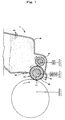
- FIG. 1 shows a typical diagram of developing device 1 that uses a nonmagnetic developing system.
- This developing device is constructed from developing roller 2, toner receptacle 4 that holds toners 3, 3.... consisting of nonmagnetic 1-component developing agent, regulating blade 5, and feed roller 6, etc.
- Above-mentioned developing roller 1 is made by forming conductive elastic layer 8 around conductive shaft 7, which consists of SUS, aluminum alloy, conductive resin, etc., and forming a single or several resin layers 9 around this conductive elastic layer 8. Direct-current voltage or alternating-current voltage is applied between this developing roller and the photosensitive body.
- feed roller 6 is installed in order to facilitate deposition of toner on the surface of the developing roller.
- Developing treatment by this type of developing device 1 is performed as follows: First, toner is deposited on the roller surface and developing roller 2 thereby charges this toner by contact or by friction. Next, the charged toner is pressed by regulating blade 5 and further uniformly charged as a toner layer of the desired thickness is produced. Moreover, this toner layer is adsorbed by the electrostatic latent image on photosensitive body 10 and the electrostatic image is thereby made visible to form a toner image. This toner image is transferred to recording paper and then the transferred image on the recording paper is fixed by heat or by pressing.
- Polyamide resin comprising -NHCO- bonds and polyurethane resin have often been used for the outermost layer of developing rolls in order to improve the minus charging properties of toners (Japanese Patent Publication (Kokoku) No. 50(1975)-13661).
- Japanese Patent Publication (Kokoku) No. 50(1975)-13661) Japanese Patent Publication (Kokoku) No. 50(1975)-13661).
- these resins as the outermost layer in that there is a reduction in the minus charge of the toner under high-temperature and high-humidity environments and further, there is a problem in that the phenomenon whereby toner is fixed on the roller surface with long-term use (referred to as "toner filming" below) occurs, preventing the formation of a toner layer, even under ordinary environments.
- polycarbonate was used as the main component of the outermost layer.
- silicone-modified polycarbonate was also used as the main component of the outermost layer (Japanese Patent Laid-Open No. 9(1997)-244392).
- silicone content of the outermost layer is high and hardness of the outermost layer is high with developing rollers that use this type of outermost layer, there is a problem in that the outermost layer is easily scratched and there is a reduction in durability of the developing roller.
- the purpose of the present invention is to prevent a reduction in the charge of the toner under high-temperature, high-humidity environments and prevent toner filming and fusion of toner on the regulating blade. Moreover, the purpose of the present invention is also to prevent fluctuations in nip width and in space width with changes in temperature and changes in humidity.
- the first developing roller of the present invention is characterized in that by means of a developing roller that is made by lamination of one or several elastic layers around a conductive shaft and one or several resin layers on said elastic layer, the above-mentioned elastic layer has a JIS A hardness of 50 degrees or less, of the above-mentioned single or several resin layers, at least the outermost layer contains fine particles, and surface roughness of said outermost layer (R z ) is adjusted to within a range of 3 to 15 ⁇ m. Furthermore, above-mentioned surface roughness (R z ) is the value in accordance with Japanese Industrial Standard (JIS) B 0601-1994.
- JIS Japanese Industrial Standard
- the mean particle diameter of the above-mentioned fine particles should be within a range of 5 to 50 ⁇ m, particularly 10 to 50 ⁇ m.
- At least the outermost layer consist of resin comprising - NHCO- bonds, for instance, polyamide resin or polyurethane resin.
- this resin composition can comprise repeating units of -ROCO 2 -, such as polycarbonate.
- these resin compositions comprise repeating units of -SiOSi-.
- At least the outermost layer consists of a resin composition comprising acrylic-vinyl acetate copolymer.
- urethane or nylon material should be used as the above-mentioned fine particles from the point that the particles impart a negative charge to the toner.
- the above-mentioned elastic layer consists of a reaction product of a curable composition whose main components are
- the thickness of the outermost layer containing the fine particles should be within a range of 5 to 50 ⁇ m.
- an outermost layer with a tensile elongation in conformance with Japanese Industrial Standards (JIS) K 6251 within a range of 300 to 600% should be used as the above-mentioned outermost layer. It is further preferred that the above-mentioned tensile elongation be adjusted to within a range of 400 to 600%, preferably 500 to 600%.
- roller resistance before coating the single or several resin layers around the elastic layer be 10 4 ⁇ or higher, and that the roller resistance after coating said resin layers be within a range of 10 4 to 10 10 ⁇ , particularly 10 5 to 10 8 ⁇ .
- capacitance before coating the single or several resin layers around the elastic layer (C 1 ) be adjusted to within a range of 0.8 to 20 nF, and that capacitance after coating with said resin layers (C 2 ) be adjusted to within a range of 2.5 nF or less.
- the above-mentioned developing roller can be used in combination with any developing device that employs the nonmagnetic contact system.
- the above-mentioned elastic layer has a JIS A hardness of 50 degrees or less, and the above-mentioned outermost layer has fine particles protruding from its surface because, of the above-mentioned single or several resin layers, at least the outermost layer contains fine particles.
- the second developing roller of the present invention is characterized in that when height of the fine particles protruding from the above-mentioned surface is L, toner mean particle diameter is r av , and mean distance between the fine particles that protrude from the above-mentioned surface is D av , the correlation of r av ⁇ D av ⁇ 80 L is established with respect to the fine particles that satisfy the correlation r av /4 ⁇ L ⁇ 4r av .
- the mean particle diameter r av of the above-mentioned toner should be within a range of 5 to 10 ⁇ m.
- This type of developing roller can be used in combination with any developing device that employs the nonmagnetic contact system.
- developing roller 10 of the present invention is made by forming conductive elastic layer 12 with a Japanese Industrial Standards (JIS) A hardness of 50 degrees or less, preferably 30 degrees or less, around conductive shaft 11, which consists of stainless steel, aluminum alloy, conductive resin, etc., and has a diameter of 1 mm to 25 mm, and then forming an single or several resin layers 13 with a thickness of 5 to 50 ⁇ m around this conductive elastic layer 12. Moreover, many fine particles are dispersed in at least the outermost layer of above-mentioned resin layers 13, and some of these fine particles protrude from the surface of the outermost layer.
- JIS Japanese Industrial Standards
- surface roughness (R z ) of this outermost layer is adjusted to within a range of 3 to 15 ⁇ m, preferably 5 to 10 ⁇ m, in accordance with JIS B 0601-1994.
- resin layer 13 can comprise an adhesive layer as the layer underneath the outermost layer in order to increase adhesion with the conductive elastic layer.
- resistance-adjusting layer for adjusting roller resistance of the developing roller as the layer underneath the outermost layer.
- the conductive elastic layer absorbs to the desired degree the pressure received from the regulating blade and prevents cracking of the toner particles. Consequently, it is possible to prevent large fluctuations in charge distribution of the toner and density irregularities and fogging of the image due to cracking of the toner particles. Moreover, as a result, fluctuations in nip width between the photosensitive body and developing roller can be prevented and therefore, a reduction in image quality can be prevented in the case of a contact developing system.
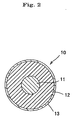
- Figure 3 is a typical example of the state where toner inside the toner receptacle has been deposited on the developing roller surface.
- Deposited toners 20, 20.... are distributed closely between fine particle 22a and fine particle 22b (or 22c) protruding from the surface of the outermost layer 21.
- these toners 20, 20.... are pushed by the regulating blade to form a toner layer with a thickness that is 1-fold to 4-fold, preferably 1-fold to 3-fold, the mean particle diameter of the toner.
- some of the pressure from the regulating blade is shouldered by protruding fine particles 22a, 22b, 22c ... and therefore, the stress applied to the toner is less than when there are no protruding fine particles.
- surface roughness (R z ) is adjusted to within a range of 3 to 15 ⁇ m, preferably 5 to 10 ⁇ m, as the degree to which the fine particles protrude from the surface layer.
- R z surface roughness
- the fine particles be harder than the resin of the outermost layer in terms of alleviating the stress applied to the toner.
- the above-mentioned toner has an average particle diameter of 5 to 10 ⁇ m, preferably 6 to 8 ⁇ m.
- the toner can be, for instance, coloring pigment coated with styrene acrylic or polyester thermoplastic resin, etc.
- urethane or nylon material be used as the above-mentioned fine particles in terms of the imparting a negative charge to the toner.
- the average particle diameter of the fine particles is 5 to 50 ⁇ m.
- roller resistance before coating the above-mentioned resin layer should be adjusted to 10 4 ⁇ or more, and roller resistance after coating said resin layer should be adjusted to within a range of 10 4 to 10 10 ⁇ , particularly 10 5 to 10 8 ⁇ . Leaking of photosensitive body and toner filming can be prevented by adjusting roller resistance after resin layer coating to within a range of 10 4 to 10 10 ⁇ , particularly 10 5 to 10 8 ⁇ . Moreover, by adjusting roller resistance before resin layer coating to 10 4 ⁇ or higher, the difference from roller resistance after resin layer coating is controlled and therefore, the generation of defects such as pin holes in the resin layer can be prevented.
- the method of determining roller resistance in this invention is performed by the following procedure in (1) through (3).
- (1) The roller is horizontally brought into contact with a metal plate horizontally and a load of 500 g is applied to the end of the shaft in the direction of the metal plate.
- (3) Roller resistance is calculated from this current and the direct-current voltage.
- capacitance (C 1 ) before coating the above-mentioned resin layer should be adjusted to within a range of 0.8 to 20 nF, while capacitance (C 2 ) after coating said resin layer should be adjusted to within a range of 2.5 nF or less.
- C 1 capacitance before coating the above-mentioned resin layer
- C 2 capacitance after coating said resin layer
- the above-mentioned residual charge is neutralized within a short amount of time by bringing the maximum capacitance after resin layer coating (C 2 ) to 2.5 nF when capacitance before resin layer coating (C 1 ) is within a range of 0.8 to 20 nF and therefore, toner filming is prevented.
- the mixture percentage of resin component in the outermost layer be adjusted and the 100% modulus of the resin composition of the outermost layer thereby be adjusted to within a range of 5 x 10 6 to 30 x 10 6 Pa, preferably 8 x 10 6 Pa to 20 x 10 6 Pa,
- the correlation of r av ⁇ D av ⁇ 80L should be established for fine particles that satisfy the correlation r av /4 ⁇ L ⁇ 4r av when mean particle diameter of the toner is r av , height of the protruding fine particles from the outermost layer surface is L, and mean distance between protruding fine particles is D av .
- the stress applied to the toner is related to the degree of protruding particle distribution.
- fine particles 23a, 23b, 23c....protruding from outermost layer 21 are distributed at the developing roller surface at various heights and surface densities. If this surface density is too high, the surface of the outermost layer is all but covered with fine particles and as a result, there is a marked reduction in the number of toner supported between protruding particles and the stress applied to the toner is too high. On the other hand, if surface density is too high, not enough fine particles will receive enough pressure from the regulating blade and too much stress will be applied to the toner.
- the fine particles are distributed so that the correlation of r av ⁇ D av ⁇ 80L will be established for fine particles that satisfy the correlation r av /4 ⁇ L ⁇ 4r av .
- Determination of the mean distance between protruding fine particles (D av ) is performed by the following procedure (1) through (3). Furthermore, the mean particle diameter (r av ) of the toner will be predetermined.
- the outermost layer should consist of a resin comprising -NHCO- bonds, such as polyurethane and polyamide. This type of resin provides the outermost layer of the developing roller with the appropriate elasticity and toner charging property.
- the outermost layer can also be made from a resin such as polycarbonate urethane that comprises both - NHCO-bonds and -R 1 OCO 2 - repeating units in 1 molecule.
- a resin such as polycarbonate urethane that comprises both - NHCO-bonds and -R 1 OCO 2 - repeating units in 1 molecule.
- This type of resin is characterized in that in addition to the appropriate elasticity and toner charging property of the resin comprising -NHCO- bonds, a low coefficient of water absorption and low dielectric constant can be maintained, even under high-temperature and high-humidity environments.
- the outermost layer consisting of this type of resin controls fluctuations in roller resistance and fluctuations in the outer diameter of the developing roller under high-temperature and high-humidity environments and thereby controls fluctuations in nip width and fluctuations in the space width between the developing roller and the photosensitive body and therefore, a reduction in image quality can be prevented.
- Polycarbonate urethane is particularly preferred because in addition to being readily obtained, it can be diluted with solvent and readily applied by dip application and spray application, etc.
- Bisphenol A groups are generally used as the R 1 of the above-mentioned -R 1 OCO 2 - repeating units, but the R 1 of the present invention is not limited to these and can also be alicyclic groups, alkyl groups, etc.
- the use of alkyl groups as R 1 is particularly preferred in terms of obtaining a resin with good balance between low hardness and low coefficient of water absorption.
- the resin of the outermost layer can also be a resin blend of a resin comprising -NHCO- bonds and resin comprising repeating units of -R 1 OCO 2 -.
- resin blends are blends of polycarbonate and polyamide or polyurethane diluted with tetrahydrofuran (THF), dimethyl formamide (DMF), etc.
- polycarbonate polyol and polyisocyanate are reacted in the presence of an appropriate solvent or without a solvent using a chain extender as needed.
- the above-mentioned chain extender can be a conventional chain extender such as glycol, amine, polyhydric alcohol, aliphatic polyamine, aromatic polyamine, etc.
- the above-mentioned polycarbonate polyol is a conventional material obtained by condensation of a polyhydric alcohol and phosgene, chloroformic acid ester, dialkyl carbonate, or diallyl carbonate.
- Preferred examples of polycarbonate polyols are obtained using 1,6-hexanediol, 1,4-butanediol, 1,3-butanediol, 1,5-pentanediol, etc., as the polyhydric alcohol, and have a number-average molecular weight (Mn) within a range of 300 to 15,000.
- polycarbonate polyol is preferably used alone, but it can also be concomitantly used with polyester polyol, polyether polyol, or polyester polyether polyol, which are conventional materials for producing polyurethane.
- the polycarbonate polyol can also be an aromatic or alicyclic polyol (mainly diol).
- Tolylene diisocyanate (TDI), 4,4-diphenylmethane diisocyanate (MDI), xylene diisocyanate (XDI), hexamethylene diisocyanate (HDI), hydrogenated MDI or isophorone diisocyanate (IPDI), etc., are used with the isocyanate that reacts with this type of polycarbonate polyol.
- hydrogenated MDI or IPDI are preferred taking into consideration the balance between toxicity, cost, ease of obtaining, and low hardness.
- resins comprising -NHCO- bonds and -SiOSi-repeating units or resins comprising -NHCO- bonds, - R 1 OCO 2 - repeating units, and -SiOSi- repeating units are preferred as the resin of the outermost layer. This is because when the outermost layer contains -SiOSi- repeating units, cohesive energy of the outermost layer is reduced when the resin of the outermost layer contains -SiOSi-repeating units and the outermost layer will have good toner release performance, preventing toner filming.
- This type of resin is obtained by reacting polyol and isocyanate in the presence of an appropriate solvent or without a solvent, using a chain extender as needed.
- polysiloxane polyol comprising -SiOSi- bonds is used for part of the above-mentioned polyol, or polyol comprising -SiOSi- bonds in its molecules is used as the above-mentioned chain extender.
- reaction intermediate of polysiloxane polyol and isocyanate where either of the reactive groups of the above-mentioned polysiloxane polyol or the isocyanate groups of the above-mentioned isocyanate remain can also be used.
- polystyrene resin for polyurethane, such as polyethylene diadipate, polyethylene butylene adipate, polytetramethylene ether glycol, poly- -caprolactone diol, polycarbonate polyol, polypropylene glycol, etc.
- polycarbonate polyol is preferred in terms of preventing a reduction in toner charge under high-temperature and high-humidity environments.
- Aliphatic or alicyclic polycarbonate polyol, such as polyhexamethylene carbonate diol is preferred as this polycarbonate polyol.
- polysiloxane polyols with the following chemical formulas I through IV are examples of polyols comprising -SiOSi- bonds that can be easily obtained:
- R 1 and R 2 are alkyl groups, fluoroalkyl groups, cycloalkyl groups, aryl groups, or substituted aryl groups, and R 3 and R 4 are alkylene groups or substituted alkylene groups.
- R 5 through R 11 are alkyl groups, fluoroalkyl groups, cycloalkyl groups, aryl groups or substituted aryl groups, and R 12 is an alkylene group or a substituted alkylene group.
- R 13 through R 17 are alkyl groups, fluoroalkyl groups, cycloalkyl groups, aryl groups or substituted aryl groups.
- R 18 through R 25 are alkyl groups, fluoroalkyl groups, cycloalkyl groups, aryl groups or substituted aryl groups. and R 26 and R 27 are alkylene groups or substituted alkylene groups.
- the polysiloxane polyol in above-mentioned chemical formulas I through IV can react with isocyanate as the main chain, or as the side chain.
- MDI 4,4'-diphenylmethane diisocyanate
- cyclohexane diisocyanate hydrogenated MDI
- isophorone diisocyanate 1,3-xylylene diisocyanate
- 2,4-tolylene diisocyanate 2,6-tolylene diisocyanate, etc.
- urethane prepolymer that has been obtained by reacting these isocyanates and polyols and polyamine so that the molecular ends have isocyanate groups can also be used.
- ethylene glycol, propylene glycol, 1,4-butanediol, 1,6-hexanediol, ethylene diamine, trimethylene diamine, tetramethylene diamine, hexamethylene diamine, isophorone diamine (IPDA), hydrazine, etc. are examples of the above-mentioned chain extender.
- the outermost layer resin can also be acrylic-vinyl acetate copolymer.
- This acrylic-vinyl acetate copolymer is a copolymer of one or both of acrylic acid ester monomer and methacrylic acid ester monomer and vinyl acetate.
- the copolymer comprise 50 wt% or more, particularly 80 wt% or more, acrylic acid ester monomer or methacrylic acid ester monomer.
- the copolymer contain 3 wt% or more, particularly 5 wt% or more, further, 10 wt% or more, vinyl acetate.
- Methyl acrylate, ethyl acrylate, butyl acrylate, 2-ethyl hexyl acrylate, etc. can be used as the above-mentioned acrylic acid ester monomer.
- methyl methacrylate, ethyl methacrylate, butyl methacrylate, etc. can be used as the above-mentioned methacrylic acid ester monomer.
- the outermost layer is formed by applying prepolymer to the conductive elastic layer and drying (depending on the case, cured) and reacting at a specific temperature.
- the conductive elastic layer consists of a reaction product of a curable composition whose main components are
- the polymer of component (A) in this curable composition is the component that goes through hydrosilylation with component (B) and is cured. Since it has at least 1 alkenyl group in its molecules, hydrosilylation occurs to make the component polymer like and the product is cured.
- the number of alkenyl groups comprising component (A) must 1 at least one in terms of hydrosilylation with component (B), but it is preferred in terms of rubber elasticity that in the case of straight-chain molecules, 2 alkenyl groups be present at both ends of the molecule and in the case of branched-chain molecules, 2 or more alkenyl groups be present at the molecular ends.
- the main repeating units forming the main chain of component (A) are oxyalkylene units or saturated hydrocarbon units.
- Polymer whose main repeating units that form its main chain are oxyalkylene units are preferred because volume resistance is brought to 10 8 to 10 9 ⁇ cm by adding a small amount of conductivity-imparting agent. Moreover, from the point of obtaining a cured product with a low hardness, oxyalkylene polymer where the above-mentioned repeating units are oxyalkylene units, and further, oxypropylene polymer where the above-mentioned repeating units are oxypropylene units, are preferred.
- the above-mentioned oxyalkylene polymer is a polymer of which 30% or more, preferably 50% or more, of the units making the main chain consist of oxyalkylene units.
- the oxyalkylene polymer may comprise units from compounds used as the starting material for polymer production with 2 or more active hydrogens, such as ethylene glycol, bisphenol compounds, glycerin, trimethylol propane, pentaerythritol, etc..
- the oxyalkylene polymer is oxypropylene polymer
- the polymer can be a copolymer with units consisting of ethylene oxide, butylene oxide, etc. (including graft copolymer).
- the molecular weight of the oxyalkylene polymer of above-mentioned component (A) should be a number-average molecular weight (Mn) of 500 to 50,000, further, 1,000 to 40,000.
- Mn number-average molecular weight
- R 1 is a hydrogen atom or methyl group.
- this curable composition is that its hardness can be easily reduced.
- the number of alkenyl groups needed to manifest this characteristic are 2 or more at the molecular ends. If there are too many alkenyl groups in comparison to molecular weight of component (A), the product will be stiff and it will be impossible to obtain good rubber elasticity.
- component (A) is a polymer whose main repeating units making its main chain are saturated hydrocarbon units, the water absorption coefficient will be low and there will be few environmental fluctuations in electrical resistance, which is preferred.
- this polymer is the component that goes through hydrosilylation with component (B) and curing. Since there is at least 1 alkenyl group in the molecules, hydrosilylation occurs to form a polymer-like substance and this substance is then cured.
- the number of alkenyl groups comprising component (A) must be at least 1 or more in terms of hydrosilylation with component (B), but in terms of rubber elasticity, there should be 2 present at both molecular ends in the case of a straight-chain molecule and 2 or more present at the molecular ends in the case of a branched molecule.
- Typical examples of polymer where the main repeating units making the above-mentioned main chain are saturated hydrocarbon units are isobutylene polymer, hydrogenated isoprene polymer, and hydrogenated butadiene polymer. These polymers can comprise repeating units of other components, such as copolymer, etc., but it is important that they comprise at least 50% or more, preferably 70% or more, more preferably 90% or more, unsaturated hydrocarbon units so that the characteristic of a low coefficient of water absorption of saturated hydrocarbons will not be lost.
- the molecular weight of the polymer of component (A) whose main repeating units making its main chain are unsaturated hydrocarbon units is 500 to 50,000, further 1,000 to 15,000, by number-average molecular weight, and a polymer that is liquid and fluid at normal temperature is preferred in terms of workability.
- alkenyl groups introduced to this saturated hydrocarbon polymer are the same as in the case of the above-mentioned oxyalkylene polymer.
- straight-chain polyisobutylene, hydrogenated polybutadiene, hydrogenated polyisoprene polymer, etc., with 2 alkenyl groups at both ends and having a number-average molecular weight (Mn) of 2,000 to 15,000 and Mw/Mn of 1.1 to 1.2 are preferred actual examples of the polymer of component (1) with at least 1 alkenyl group in its molecules and whose main repeating units making the main chain are saturated hydrocarbon. Furthermore, Mw is the weight-average molecular weight.
- component (B) of the curable composition is a compound with at least 2 hydrosilyl groups in its molecules, if the number of hydrosilyl groups contained in the molecules is too high, large amounts of hydrolsilyl groups will easily remain in the cured product becoming a source of voids and cracks and therefore, the number of hydrosilyl groups contained in the molecules should be 50 or less.
- hydrosilyl groups in terms of controlling rubber elasticity of the cured product and shelf life, and further, 20 or fewer hydrosilyl groups are needed in order to easily prevent bubbling during curing and even if the hydrosilyl groups are deactivated, 2 are necessary, the preferred range being 3 to 20, in order to avoid poor curing.
- the above-mentioned 1 hydrosilyl group means that there is 1 H bonded to Si.
- There are 2 hydrosilyl groups in SiH 2 but curability is better when the H bonded to the Si is bonded to different Si atoms. This is also preferred in terms of rubber elasticity.
- Molecular weight of component (B) should be 30,000 or less, further 20,000 or less, particularly 15,000 or less, by number-average molecular weight (Mn) in terms of dispersability and roller workability when conductivity-imparting agent (component (D)) described below is added.
- Mn number-average molecular weight
- component (D) conductivity-imparting agent
- component (B) since cohesive force of component (A) is large in comparison to the cohesive force of component (B), modification to include phenyl groups is important in terms of solubility and styrene modified product, etc., is preferred in terms of solubility with component (A) and ease of obtaining, while ⁇ -methyl styrene modification is preferred in terms of shelf life.
- hydrosilylation catalyst that is component (C)
- component (C) there are no particular restrictions to the hydrosilylation catalyst that is component (C) as long as it can be used as a hydrosilylation catalyst.
- These catalysts can be used alone or 2 or more can be used together.
- the ratio of use of component (A) and component (B) in the curable composition should be 0.2 to 5.0 moles, preferably 0.4 to 2.5 moles, hydrosilyl groups in component (B) per 1 mole alkenyl groups in component (A) in terms of rubber elasticity.
- the amount of component (C) used is 10 -1 to 10 -8 mole, further, 10 -1 to 10 -6 mole, particularly 10 -3 to 10 -6 mole, per 1 mole alkenyl groups in component (A). If the amount of component (C) used is less than 10 -8 mole, the reaction will not proceed. On the other hand, hydrosilylation catalysts are generally expensive and they are corrosive and generate large quantities of hydrogen gas, causing the cured product to bubble. Therefore, the amount used should not exceed 10 -1 mole.
- the curable composition is an ideal developing roller.
- the conductivity-imparting agent for this component (D) are compounds that can provide conductivity, including carbon black and metal micropowders, and further. organic compounds or polymers with quaternary ammonium salt groups, carboxylic acid groups, sulfonic acid groups, sulfuric acid ester groups, phosphoric acid ester groups, etc., compounds and polymers with conductive units represented by ether stearamide, ether imide copolymer, ethylene oxide-epihalohydrin copolymer, and methoxypolyethylene glycol acrylate, etc. These conductivity-imparting agents can be used alone, or 2 or more can be used together.
- the amount of conductivity-imparting agent, which is component (D), should be 30 wt% or less in terms of the total amount of components (A) through (C) from the point of not increasing rubber hardness. In the other hand, in order to obtain uniform resistance, the amount should be 10 wt% or more. Therefore, the amount added should be determined from the property balance so that the necessary. rubber hardness is obtained and volume resistance of the cured product is 10 3 to 10 10 ⁇ cm.
- shelf life improvers such as compounds with aliphatic unsaturated bonds, organic phosphorus compounds, organic sulfur compounds, nitrogen-containing compounds, tin compounds, organic peroxides, etc.
- shelf life improvers such as compounds with aliphatic unsaturated bonds, organic phosphorus compounds, organic sulfur compounds, nitrogen-containing compounds, tin compounds, organic peroxides, etc.
- Actual examples are benzothiazole, thiazole, dimethyl malate, dimethyl acetylene carboxylate, 2-pentene nitrile, 2,3-dichloropropene, quinoline, etc., but they are not limited to these examples.
- thiazole and dimethyl malate are particularly preferred in terms of both pot life and fast curing.
- the above-mentioned shelf life improvers can be used alone, or 2 or more can be used together.
- filler for example, filler, shelf life stabilizer, plasticizer, ultraviolet ray absorbing agent, lubricant, pigment, etc., can be added to the above-mentioned curable composition to improve workability and cost.
- the conductive elastic layer is formed around the above-mentioned conductive shaft by for instance, pouring, injection molding, extrusion molding, etc., the above-mentioned curable composition and elastic material, such as urethane rubber, silicone rubber, etc., into a mold with the conductive shaft made of SUS or aluminum alloy in the center and heating and curing the product at the appropriate temperature and for the appropriate time.
- the product can be post-cured after being semi-cured.
- the developing roller of Examples 1 through 9 and Comparative Examples 1 and 2 has conductive elastic layer with a thickness of approximately 7.5 mm formed around a stainless steel shaft with a diameter of 10 mm and an outermost layer with a specific thickness is coated around the outside of this conductive elastic layer.
- This conductive elastic layer and outermost layer are the combinations of conductive elastic layers 1 through 3 and outermost layers 1 through 9 listed below:
- Each component was mixed in accordance with the following mixture 1 and defoamed under reduced pressure for 120 minutes at 10 mmHg or less to obtain a resin composition.
- This resin composition was coated around a shaft and cured by being set aside for 30 minutes under an environment of 120°C in the mold.
- JIS A hardness as specified by Japanese Industrial Standards (JIS) K 6301 of conductive elastic layer 1 obtained in this way was 15 degrees.
- A-1) 100 Oxypropylene copolymer with terminal aryl groups (Number-average molecular weight (Mn) 8,000; molecular weight distribution 2)
- B-1) 6.6 Polysiloxane curing agent (SiH value of 0.36 mole per 100 g)
- C-1) 0.06 10% isopropyl alcohol solution of chloroplatinic acid
- D-1) 7 Carbon black (brand name "3030B", produced by Mitsubishi chemical Co., Ltd.)
- Each component was mixed in accordance with the following mixture 2 and defoamed under reduced pressure for 120 minutes at 10 mmHg or less to obtain a resin composition.
- This resin composition was coated around a shaft and cured by being set aside in the mold for 30 minutes under an environment of 120°C.
- JIS A hardness as specified by Japanese Industrial Standards (JIS) K 6301 of conductive elastic layer 2 obtained in this way was 15 degrees.
- A-2) 100 Polyisobutylene polymer with 2 vinyl groups at the ends (Number-average molecular weight (Mn) 10,000)
- B-2) 2.7 Polysiloxane curing agent (SiH value of 0.97 mole per 100 g)
- C-1) 0.06 10% isopropyl alcohol solution of chloroplatinic acid
- D-1) 7 Carbon black brand name "3030B", produced by Mitsubishi chemical Co., Ltd.
- E-1) 75 Plasticizer brand name "PS-32", produced by Idemitsu Kosan Co., Ltd.
- Ketjen black EC mixed per 100 g NBR rubber brand name "Chemigum N683B", produced by Goodyear Co., Ltd.; bonded acrylonitrile content of 33%, Mooney viscosity of 28 (ML-4-100°C)
- JIS A hardness as specified by Japanese Industrial Standards (JIS) K 6301 of conductive elastic layer 3 was 45 degrees.
- This solution was coated around the conductive elastic layer by dipping and dried to form outermost layer 1 with a thickness of approximately 15 ⁇ m.
- Surface roughness (R z ) of outermost layer 1 was approximately 1.9 ⁇ m.
- This solution was coated around the conductive elastic layer by dipping and dried to form outermost layer 1 with a thickness of approximately 20 ⁇ m.
- Surface roughness (R z ) of outermost layer 2 was approximately 3.1 ⁇ m.
- This solution was applied around the conductive elastic layer by dipping and dried to form outermost layer 3 with a thickness of approximately 20 ⁇ m.
- Surface roughness (R z ) of outermost layer 3 was approximately 6.3 ⁇ m.
- This solution was applied around the conductive elastic layer by dipping and dried to form outermost layer 4 with a thickness of approximately 16 ⁇ m.
- Surface roughness (R z ) of outermost layer 4 was approximately 3.6 ⁇ m.
- This solution was applied around the conductive elastic layer by dipping and dried to form outermost layer 6 with a thickness of approximately 20 ⁇ m.
- Surface roughness (R z ) of outermost layer 6 was approximately 7.8 ⁇ m.
- This solution was applied around the conductive elastic layer by dipping and dried to form outermost layer 7 with a thickness of approximately 20 ⁇ m.
- Surface roughness (R z ) of outermost layer 7 was approximately 2.1 ⁇ m.
- Mixture 8 Parts by weight Polycarbonate urethane (brand name "E980", produced by Nihon Mirakutoran Co., Ltd.) 100 Acrylic fine particles (brand name "Epostar MA1006", produced by Nippon Shokubai Co., Ltd. ; average particle diameter of 5 ⁇ m) 8
- Example 1 1 3 6.3 ⁇ m 65 ⁇ m 6.2 ⁇ m
- Example 2 2 3 6.3 ⁇ m 60 ⁇ m 5.7 ⁇ m
- Example 3 3 3 6.3 ⁇ m 65 ⁇ m 5.8 ⁇ m
- Example 4 1 2 3.1 ⁇ m 95 ⁇ m 3.4 ⁇ m
- Example 5 1 4 3.6 ⁇ m 85 ⁇ m 2.6 ⁇ m
- Example 6 1 5 8.1 ⁇ m 45 ⁇ m 8.2 ⁇ m
- Example 7 1 6 7.8 ⁇ m
- Example 8 1 8 14.3 ⁇ m 150 ⁇ m 14.0 ⁇ m
- Example 9 1 9 3.2 ⁇ m 85 ⁇ m 2.8 ⁇ m Comparative Example 1 1 1 1.9 ⁇ m None None Comparative Example 2 1 7 2.1 ⁇ m 380 ⁇ m 1.7 ⁇ m
- the experiments were performed by printing 3,000 black set-solid images using the developing roller in combination with a contact-type developing device. Average particle diameter of the nonmagnetic toner used in the experiments was 10 ⁇ m, and the melting point of the nonmagnetic toner was 78°C. Evaluation of the experiments was performed on the 2 points of (1) printing density and (2) fusion of toner to regulating blade.
- the regulating blade was macroscopically checked and toner fusion was evaluated as "A” (excellent) when there was almost no fusion of toner on the regulating blade, "B” (good) when there was slight fusion, and "C” (no good) when there was obvious fusion.
- the developing rollers of Examples 10 through 18 and Comparative Examples 3 through 5 were made by forming a conductive elastic layer with a thickness of approximately 7.5 mm around a stainless steel shaft with a diameter of 10 mm and then coating an outermost layer of a specific thickness around the outside of this conductive elastic layer.
- the conductive elastic layer and outermost layer were a combination of above-mentioned conductive elastic layer 1 and outermost layers 10 through 21 listed below.
- the mixture shown by the following mixture 11 was introduced to a 2,000 ml flask with 3 openings and reacted while being agitated for 3 hours under a 100°C environment to obtain prepolymer with NCO groups at the molecular ends.
- this prepolymer was cooled to 50°C, it was mixed with 580 g DMF (dimethyl formamide) to obtain a solution.
- DMF dimethyl formamide
- IPDA isophorone diamine
- a chain extension reaction 40°C, 3 hours
- the mixture shown by the following mixture 12 was introduced to a 2,000 ml (milliliter) flask with 3 openings and reacted while being agitated for 4 hours under a 100°C environment to obtain prepolymer with NCO groups at the molecular ends. After this prepolymer was cooled to 50°C, it was mixed with 580 g DMF (dimethyl formamide) to obtain a solution. Then 16 g IPDA (isophorone diamine) were gradually added dropwise to this solution and a chain extension reaction (40°C, 3 hours) was performed to obtain solid content. Twenty parts by weight urethane fine particles (brand name " Seikaseven UP0908", produced by Dainichiseika Co., Ltd.
- urethane fine particles brand name " Seikaseven UP0904", produced by Dainichiseika Co., Ltd.; average particle diameter of 15 ⁇ m
- This outermost layer solution was covered on the conductive elastic layer by dipping and dried for 1 hour at 80°C to form outermost layer 12.
- Surface roughness (R z ) of this outermost layer 12 was approximately 6 ⁇ m.
- PMMA particles brand name "MA1013", produced by Nippon Shokubai Co., Ltd.; average particle diameter of 15 ⁇ m
- This outermost layer solution was covered on the conductive elastic layer by dipping and dried for 1 hour at 80°C to form outermost layer 13.
- Surface roughness (R z ) of this outermost layer 13 was approximately 6 ⁇ m.
- a mixture of polyol which was a mixture of polysiloxane polyol and carbonate polyol at a weight ratio of 8:2, and hydrogenated MDI was introduced to a 2,000 ml (milliliter) flask with 3 openings and reacted while being agitated for 4 hours under a 100°C environment to obtain prepolymer with NCO groups at the molecular ends. After this prepolymer was cooled to 50°C, it was mixed with DMF (dimethyl formamide) to obtain a solution. Then IPDA (isophorone diamine) was gradually added dropwise to this solution and a chain extension reaction was performed at 40°C for 3 hours to obtain solid content.
- DMF dimethyl formamide
- urethane fine particles brand name " Seikaseven UP0904", produced by Dainichiseika Co., Ltd. ;average particle diameter of 15 ⁇ m
- This outermost layer solution was coated around the conductive elastic layer by dipping and dried for 1 hour at 80°C to form outermost layers 14 through 18.
- Surface roughness (R Z ) of these outermost layers was approximately 5 to 7 ⁇ m. 100% modulus (10 6 Pa) Outermost layer 14 4 Outermost layer 15 8 Outermost layer 16 17 Outermost layer 17 25 Outermost layer 18 33
- This outermost layer solution was coated around the conductive elastic layer by dipping and dried for 1 hour at 80°C to form outermost layer 19.
- Surface roughness (R z ) of this outermost layer was approximately 2 ⁇ m.
- the solid content of vinylidene fluoride (brand name "Sefral Soft G-180Y", produced by Central Glass K. K.) was diluted to approximately 5% with DMF solution to obtain the outermost layer solution.
- This outermost layer solution was coated around the conductive elastic layer by dipping and dried for 1 hour at 80°C to form outermost layer 20.
- Surface roughness (R z ) of this outermost layer 20 was approximately 1 ⁇ m.
- the solid content of methoxymethylated nylon (brand name "EM-120”. produced by Namariichi Co., Ltd.) was diluted to approximately 10% with methanol obtain the outermost layer solution.
- This outermost layer solution was coated around the conductive elastic layer by dipping and dried for 1 hour at 80°C to form outermost layer 21.
- Surface roughness (R z ) of this outermost layer 21 was approximately 1 ⁇ m.
- the experiments were performed by printing 5,000 black set-solid images using the developing roller in combination with a contact-type developing device. Average particle diameter of the nonmagnetic toner used in the experiments was 10 ⁇ m, and the melting point of the nonmagnetic toner was 78°C. A stainless steel regulating blade was used. Evaluation of the experiments was performed on the 3 points of (1) printing density, (2) toner filming, and (3) fusion of toner to regulating blade.
- Density of the 100th and the 5,000th black set-solid image was determined with a Macbeth densitometer. Density was evaluated as "A” (excellent) when this determination was 1.4 or higher, “B” (fairly good) if it was 1.35 or higher but under 1.4, “C” (insufficient) if it was 1.3 or higher but under 1.35, and “D” (no good) if it was under 1.3.
- the surface of the developing roller after printing 5,000 prints was macroscopically checked and if there was no toner filming whatsoever, it was evaluated as "A” (excellent), it there was almost no toner filming, it was evaluated as “B” (good), and if there was toner filming in several places, it was evaluated as “C” (no good).
- the regulating blade was macroscopically checked and toner fusion was evaluated as "A” (excellent) when there was almost no fusion of toner on the regulating blade, "B” (good) when there was slight fusion, and "C” (no good) when there was obvious fusion.
- the developing roller of the present invention is ideal for incorporation in developing devices that use nonmagnetic one-component developing agents for image-forming devices that employ electrophotography, including copying machines, printers, the receivers of facsimiles, etc.
Landscapes
- Engineering & Computer Science (AREA)
- General Engineering & Computer Science (AREA)
- Physics & Mathematics (AREA)
- General Physics & Mathematics (AREA)
- Mechanical Engineering (AREA)
- Dry Development In Electrophotography (AREA)
Applications Claiming Priority (13)
| Application Number | Priority Date | Filing Date | Title |
|---|---|---|---|
| JP17614397 | 1997-07-01 | ||
| JP17614397A JP3794111B2 (ja) | 1997-07-01 | 1997-07-01 | 現像ローラ |
| JP24508197 | 1997-09-10 | ||
| JP24508197A JP3829430B2 (ja) | 1997-09-10 | 1997-09-10 | 現像ローラ |
| JP32588097A JP3832057B2 (ja) | 1997-11-27 | 1997-11-27 | 現像ローラの製造方法 |
| JP32588097 | 1997-11-27 | ||
| JP33412297A JP3800773B2 (ja) | 1997-12-04 | 1997-12-04 | 電子写真方式に用いるローラ |
| JP33412297 | 1997-12-04 | ||
| JP33875097 | 1997-12-09 | ||
| JP33875097A JP3800774B2 (ja) | 1997-12-09 | 1997-12-09 | 表面に海島構造を有する現像ローラ |
| JP986998 | 1998-01-21 | ||
| JP986998A JP3829454B2 (ja) | 1998-01-21 | 1998-01-21 | 現像ローラ |
| PCT/JP1998/002947 WO1999001800A1 (fr) | 1997-07-01 | 1998-06-29 | Rouleau de developpement et dispositif de developpement utilisant ce rouleau |
Publications (1)
| Publication Number | Publication Date |
|---|---|
| EP1014212A1 true EP1014212A1 (fr) | 2000-06-28 |
Family
ID=27548232
Family Applications (1)
| Application Number | Title | Priority Date | Filing Date |
|---|---|---|---|
| EP98929770A Withdrawn EP1014212A1 (fr) | 1997-07-01 | 1998-06-29 | Rouleau de developpement et dispositif de developpement utilisant ce rouleau |
Country Status (5)
| Country | Link |
|---|---|
| US (1) | US6360069B1 (fr) |
| EP (1) | EP1014212A1 (fr) |
| KR (1) | KR100356916B1 (fr) |
| CN (1) | CN1112606C (fr) |
| WO (1) | WO1999001800A1 (fr) |
Cited By (4)
| Publication number | Priority date | Publication date | Assignee | Title |
|---|---|---|---|---|
| WO2003087954A1 (fr) * | 2002-04-12 | 2003-10-23 | Bridgestone Corporation | Rouleau conducteur et appareil de formation d'image |
| EP1906263A3 (fr) * | 2006-09-29 | 2010-01-27 | Canon Kabushiki Kaisha | Élément de développement et appareil électrophotographique de formation d'images |
| EP1901135A3 (fr) * | 2006-09-14 | 2010-01-27 | Canon Kabushiki Kaisha | Élément de développement, ensemble de développement et appareil électrophotographique de formation d'images |
| EP3605239A1 (fr) * | 2018-07-31 | 2020-02-05 | Canon Kabushiki Kaisha | Élément électrophotographique, cartouche de processus électrophotographique et appareil de formation d'images électrophotographiques |
Families Citing this family (46)
| Publication number | Priority date | Publication date | Assignee | Title |
|---|---|---|---|---|
| JP3899756B2 (ja) * | 1999-12-16 | 2007-03-28 | 株式会社カネカ | 電子写真用ローラ |
| JP2002055521A (ja) * | 2000-08-10 | 2002-02-20 | Minolta Co Ltd | 現像装置及び画像形成装置 |
| CN100354766C (zh) * | 2001-06-22 | 2007-12-12 | 夏普株式会社 | 显影装置及图像形成装置 |
| JP3661644B2 (ja) * | 2001-12-28 | 2005-06-15 | ブラザー工業株式会社 | 現像装置および画像形成装置 |
| JP4467944B2 (ja) * | 2002-10-30 | 2010-05-26 | キヤノン株式会社 | 現像剤担持体及び現像装置 |
| US7172543B2 (en) * | 2002-11-15 | 2007-02-06 | Sumitomo Rubber Industries, Ltd. | Conductive roller |
| JP2004191561A (ja) * | 2002-12-10 | 2004-07-08 | Bridgestone Corp | 現像ローラ及び画像形成装置 |
| US7162187B2 (en) * | 2003-06-30 | 2007-01-09 | Ricoh Company, Ltd. | Image forming apparatus and image forming method |
| JP4262044B2 (ja) * | 2003-10-10 | 2009-05-13 | キヤノン株式会社 | 現像ローラ、電子写真プロセスカートリッジ及び電子写真画像形成装置 |
| JP3826125B2 (ja) * | 2003-10-14 | 2006-09-27 | キヤノン株式会社 | 現像ローラ、電子写真プロセスカートリッジ及び電子写真画像形成装置 |
| US7013104B2 (en) * | 2004-03-12 | 2006-03-14 | Lexmark International, Inc. | Toner regulating system having toner regulating member with metallic coating on flexible substrate |
| US6970672B2 (en) * | 2004-03-25 | 2005-11-29 | Lexmark International, Inc. | Electrophotographic toner regulating member with polymer coating having surface roughness modified by fine particles |
| US7811738B2 (en) * | 2004-06-01 | 2010-10-12 | Zeon Corporation | Image forming method |
| JP2005352014A (ja) * | 2004-06-09 | 2005-12-22 | Bridgestone Corp | 現像ローラ及びそれを備えた画像形成装置 |
| CN100511010C (zh) * | 2004-06-09 | 2009-07-08 | 株式会社普利司通 | 显影辊和使用其的图像形成装置 |
| US7236729B2 (en) * | 2004-07-27 | 2007-06-26 | Lexmark International, Inc. | Electrophotographic toner regulating member with induced strain outside elastic response region |
| WO2006070904A1 (fr) * | 2004-12-28 | 2006-07-06 | Canon Kabushiki Kaisha | Element de charge, cartouche de traitement et appareil electrophotographique |
| CN100461019C (zh) * | 2005-03-08 | 2009-02-11 | 株式会社普利司通 | 导电性辊和使用该导电性辊的图像形成装置 |
| JP4555181B2 (ja) * | 2005-07-14 | 2010-09-29 | 株式会社リコー | 画像形成装置 |
| JP4821271B2 (ja) * | 2005-11-02 | 2011-11-24 | セイコーエプソン株式会社 | 現像装置、トナー粒子担持ローラ、画像形成装置、画像形成システム、及び、トナー粒子担持ローラの製造方法 |
| CN102004417A (zh) | 2005-11-02 | 2011-04-06 | 精工爱普生株式会社 | 调色剂颗粒承载辊、以及显影装置 |
| JP5204951B2 (ja) * | 2005-11-11 | 2013-06-05 | 株式会社ブリヂストン | 現像ローラ及びそれを備えた画像形成装置 |
| US8550968B2 (en) | 2005-11-11 | 2013-10-08 | Bridgestone Corporation | Developing roller and imaging apparatus comprising the same |
| JP2007333829A (ja) * | 2006-06-13 | 2007-12-27 | Konica Minolta Business Technologies Inc | トナー供給ローラ、現像装置および画像形成装置 |
| US7831183B2 (en) * | 2006-09-20 | 2010-11-09 | Konica Minolta Business Technologies, Inc. | Electrophotograph developing roller and developing apparatus employing the same |
| KR101049326B1 (ko) * | 2006-10-06 | 2011-07-13 | 캐논 가부시끼가이샤 | 현상 롤러, 그것을 사용한 현상 장치 및 화상 형성 장치 |
| JP4816413B2 (ja) * | 2006-11-07 | 2011-11-16 | セイコーエプソン株式会社 | 現像ローラの製造方法、現像装置および画像形成装置 |
| JP5088565B2 (ja) * | 2007-03-09 | 2012-12-05 | コニカミノルタビジネステクノロジーズ株式会社 | 現像ローラ、及び、該現像ローラを用いた画像形成方法 |
| US8038591B2 (en) * | 2007-03-27 | 2011-10-18 | Lexmark International, Inc. | Image forming apparatus component with triboelectric properties |
| US8086152B2 (en) * | 2007-05-30 | 2011-12-27 | Seiko Epson Corporation | Developing device, image forming apparatus, image forming system, developing method, and toner bearing member |
| JP4862748B2 (ja) * | 2007-05-30 | 2012-01-25 | セイコーエプソン株式会社 | 現像装置、画像形成装置、及び、画像形成システム |
| JP4684281B2 (ja) * | 2007-11-15 | 2011-05-18 | 株式会社ブリヂストン | トナー搬送ローラおよびそれを用いた画像形成装置 |
| JP2009237463A (ja) * | 2008-03-28 | 2009-10-15 | Konica Minolta Business Technologies Inc | 現像ローラ |
| CN102483595B (zh) * | 2009-08-05 | 2015-01-14 | 信越聚合物股份有限公司 | 导电性辊及图像形成装置 |
| CN103282839B (zh) | 2010-12-28 | 2015-10-14 | 佳能株式会社 | 显影辊、处理盒和电子照相设备 |
| WO2013028183A1 (fr) * | 2011-08-24 | 2013-02-28 | Hewlett-Packard Development Company, L.P. | Revêtement de rouleau |
| CN102436161B (zh) * | 2011-12-26 | 2014-05-07 | 珠海赛纳打印科技股份有限公司 | 导电弹性体辊及其制造方法和图像形成装置 |
| CN104119774A (zh) * | 2014-07-28 | 2014-10-29 | 珠海市科力莱科技有限公司 | 一种显影磁辊涂层 |
| US9897931B2 (en) * | 2014-11-28 | 2018-02-20 | Canon Kabushiki Kaisha | Electroconductive member for electrophotography, process cartridge, and electrophotographic image-forming apparatus |
| CN105988337B (zh) * | 2015-03-18 | 2020-03-10 | 株式会社理光 | 显影辊,调色剂以及图像形成装置 |
| JP6149075B2 (ja) * | 2015-07-30 | 2017-06-14 | 住友理工株式会社 | 電子写真機器用クリーニングブレード用組成物および電子写真機器用クリーニングブレード |
| JP6660555B2 (ja) * | 2015-12-21 | 2020-03-11 | 住友ゴム工業株式会社 | 現像ローラおよびその製造方法 |
| CN109416519A (zh) * | 2016-06-20 | 2019-03-01 | 株式会社普利司通 | 导电性辊 |
| CN110741321B (zh) | 2017-06-27 | 2020-10-30 | Nok株式会社 | 显影辊 |
| JP2019174535A (ja) * | 2018-03-27 | 2019-10-10 | 株式会社沖データ | 現像ユニットおよび画像形成装置 |
| EP3901476A4 (fr) * | 2018-12-17 | 2022-09-21 | Archem Inc. | Rouleau de charge et dispositif de formation d'image |
Family Cites Families (12)
| Publication number | Priority date | Publication date | Assignee | Title |
|---|---|---|---|---|
| US4994319A (en) * | 1987-05-30 | 1991-02-19 | Ricoh Company, Ltd. | Member for developing electrostatic latent images |
| JP3112489B2 (ja) | 1991-03-29 | 2000-11-27 | 株式会社東芝 | 現像装置 |
| US5434653A (en) * | 1993-03-29 | 1995-07-18 | Bridgestone Corporation | Developing roller and apparatus |
| DE4411017C2 (de) * | 1994-03-30 | 1995-06-08 | Alexander Dr Knuettel | Optische stationäre spektroskopische Bildgebung in stark streuenden Objekten durch spezielle Lichtfokussierung und Signal-Detektion von Licht unterschiedlicher Wellenlängen |
| JPH08179619A (ja) | 1994-12-26 | 1996-07-12 | Bridgestone Corp | 現像ローラ |
| US5666626A (en) * | 1995-03-10 | 1997-09-09 | Bridgestone Corporation | Apparatus for developing electrostatic latent images using developing roller having specific ionization potential |
| US5697027A (en) * | 1995-09-20 | 1997-12-09 | Bridgestone Corporation | Developing roller employing an elastic layer between conductive shaft and outer conductive layer and developing apparatus |
| JPH1039614A (ja) | 1996-07-25 | 1998-02-13 | Kanegafuchi Chem Ind Co Ltd | 現像ローラ |
| US5878313A (en) * | 1996-09-02 | 1999-03-02 | Bridgestone Corporation | Developing roller and apparatus |
| JP3539114B2 (ja) * | 1997-03-11 | 2004-07-07 | 東海ゴム工業株式会社 | 現像ロールおよびその製法 |
| US6067434A (en) * | 1997-06-27 | 2000-05-23 | Bridgestone Corporation | Developing roller and developing apparatus |
| JP2978865B2 (ja) * | 1997-11-28 | 1999-11-15 | 新潟日本電気株式会社 | 画像形成装置 |
-
1998
- 1998-06-29 EP EP98929770A patent/EP1014212A1/fr not_active Withdrawn
- 1998-06-29 CN CN98806537A patent/CN1112606C/zh not_active Expired - Fee Related
- 1998-06-29 US US09/446,633 patent/US6360069B1/en not_active Expired - Lifetime
- 1998-06-29 KR KR1019997011740A patent/KR100356916B1/ko not_active Expired - Fee Related
- 1998-06-29 WO PCT/JP1998/002947 patent/WO1999001800A1/fr not_active Ceased
Non-Patent Citations (1)
| Title |
|---|
| See references of WO9901800A1 * |
Cited By (7)
| Publication number | Priority date | Publication date | Assignee | Title |
|---|---|---|---|---|
| WO2003087954A1 (fr) * | 2002-04-12 | 2003-10-23 | Bridgestone Corporation | Rouleau conducteur et appareil de formation d'image |
| EP1901135A3 (fr) * | 2006-09-14 | 2010-01-27 | Canon Kabushiki Kaisha | Élément de développement, ensemble de développement et appareil électrophotographique de formation d'images |
| US7983605B2 (en) | 2006-09-14 | 2011-07-19 | Canon Kabushiki Kaisha | Developing member with urethane resin and silicone surface layer |
| EP1906263A3 (fr) * | 2006-09-29 | 2010-01-27 | Canon Kabushiki Kaisha | Élément de développement et appareil électrophotographique de formation d'images |
| US7799398B2 (en) | 2006-09-29 | 2010-09-21 | Canon Kabushiki Kaisha | Developing member and electrophotographic image forming apparatus |
| EP3605239A1 (fr) * | 2018-07-31 | 2020-02-05 | Canon Kabushiki Kaisha | Élément électrophotographique, cartouche de processus électrophotographique et appareil de formation d'images électrophotographiques |
| US10571825B1 (en) | 2018-07-31 | 2020-02-25 | Canon Kabushiki Kaisha | Electrophotographic member, electrophotographic process cartridge and electrophotographic image forming apparatus |
Also Published As
| Publication number | Publication date |
|---|---|
| KR20010013725A (ko) | 2001-02-26 |
| CN1112606C (zh) | 2003-06-25 |
| KR100356916B1 (ko) | 2002-10-18 |
| CN1261446A (zh) | 2000-07-26 |
| US6360069B1 (en) | 2002-03-19 |
| WO1999001800A1 (fr) | 1999-01-14 |
Similar Documents
| Publication | Publication Date | Title |
|---|---|---|
| US6360069B1 (en) | Roller for electrophotographic systems having surface roughness adjusted by fine particles | |
| JP5931846B2 (ja) | 導電性ローラ、現像装置及び画像形成装置 | |
| EP0982335B1 (fr) | Rouleau conducteur | |
| EP2869130B1 (fr) | Élément de développement, cartouche de traitement et dispositif d'électrophotographie | |
| US7007384B2 (en) | Developing roller and method of producing the same | |
| US20160363881A1 (en) | Electro-conductive member, process cartridge and electrophotographic apparatus | |
| JP2012042574A (ja) | 現像ローラ、現像装置及び画像形成装置 | |
| JP3829454B2 (ja) | 現像ローラ | |
| JP3832057B2 (ja) | 現像ローラの製造方法 | |
| US6534180B2 (en) | Charge-imparting member | |
| JP3800774B2 (ja) | 表面に海島構造を有する現像ローラ | |
| JP3899756B2 (ja) | 電子写真用ローラ | |
| JP4061777B2 (ja) | 被覆層を有するゴムローラの製造方法 | |
| JP5022686B2 (ja) | 現像ローラの製造方法 | |
| JP4208765B2 (ja) | 現像ローラ、プロセスカートリッジ及び画像形成装置 | |
| JP5577207B2 (ja) | 導電性ローラ、その製造方法、現像装置及び画像形成装置 | |
| JP3794111B2 (ja) | 現像ローラ | |
| JP5361342B2 (ja) | 現像ローラ、現像ローラの製造方法、プロセスカートリッジ及び電子写真用画像形成装置 | |
| WO1999034123A1 (fr) | Rouleau eponge et procede de fabrication | |
| JP3565021B2 (ja) | 現像ローラ | |
| JP5729866B2 (ja) | 導電性ローラ、現像装置及び画像形成装置 | |
| JP2016070996A (ja) | 導電性ローラ、現像装置及び画像形成装置 | |
| JP3829430B2 (ja) | 現像ローラ | |
| JP2020197665A (ja) | 現像ローラ、現像装置及び画像形成装置 | |
| JP3800773B2 (ja) | 電子写真方式に用いるローラ |
Legal Events
| Date | Code | Title | Description |
|---|---|---|---|
| PUAI | Public reference made under article 153(3) epc to a published international application that has entered the european phase |
Free format text: ORIGINAL CODE: 0009012 |
|
| 17P | Request for examination filed |
Effective date: 20000118 |
|
| AK | Designated contracting states |
Kind code of ref document: A1 Designated state(s): DE FR GB IT |
|
| STAA | Information on the status of an ep patent application or granted ep patent |
Free format text: STATUS: THE APPLICATION IS DEEMED TO BE WITHDRAWN |
|
| 18D | Application deemed to be withdrawn |
Effective date: 20080101 |