EP1018796A2 - Stepping motor - Google Patents
Stepping motor Download PDFInfo
- Publication number
- EP1018796A2 EP1018796A2 EP99124915A EP99124915A EP1018796A2 EP 1018796 A2 EP1018796 A2 EP 1018796A2 EP 99124915 A EP99124915 A EP 99124915A EP 99124915 A EP99124915 A EP 99124915A EP 1018796 A2 EP1018796 A2 EP 1018796A2
- Authority
- EP
- European Patent Office
- Prior art keywords
- brackets
- stator
- support members
- stator core
- peripheral surface
- Prior art date
- Legal status (The legal status is an assumption and is not a legal conclusion. Google has not performed a legal analysis and makes no representation as to the accuracy of the status listed.)
- Granted
Links
- 230000002093 peripheral effect Effects 0.000 claims abstract description 22
- 230000003014 reinforcing effect Effects 0.000 claims 1
- 238000004804 winding Methods 0.000 claims 1
- 238000003780 insertion Methods 0.000 description 5
- 230000037431 insertion Effects 0.000 description 5
- 239000011248 coating agent Substances 0.000 description 3
- 238000000576 coating method Methods 0.000 description 3
- 229920002313 fluoropolymer Polymers 0.000 description 3
- 238000012986 modification Methods 0.000 description 3
- 230000004048 modification Effects 0.000 description 3
- 229910000831 Steel Inorganic materials 0.000 description 1
- 230000005534 acoustic noise Effects 0.000 description 1
- 230000000052 comparative effect Effects 0.000 description 1
- 230000001419 dependent effect Effects 0.000 description 1
- 229920001971 elastomer Polymers 0.000 description 1
- 230000002452 interceptive effect Effects 0.000 description 1
- 230000000452 restraining effect Effects 0.000 description 1
- 239000005060 rubber Substances 0.000 description 1
- 239000010959 steel Substances 0.000 description 1
- 238000004381 surface treatment Methods 0.000 description 1
Images


Classifications
-
- H—ELECTRICITY
- H02—GENERATION; CONVERSION OR DISTRIBUTION OF ELECTRIC POWER
- H02K—DYNAMO-ELECTRIC MACHINES
- H02K37/00—Motors with rotor rotating step by step and without interrupter or commutator driven by the rotor, e.g. stepping motors
- H02K37/10—Motors with rotor rotating step by step and without interrupter or commutator driven by the rotor, e.g. stepping motors of permanent magnet type
- H02K37/12—Motors with rotor rotating step by step and without interrupter or commutator driven by the rotor, e.g. stepping motors of permanent magnet type with stationary armatures and rotating magnets
- H02K37/14—Motors with rotor rotating step by step and without interrupter or commutator driven by the rotor, e.g. stepping motors of permanent magnet type with stationary armatures and rotating magnets with magnets rotating within the armatures
- H02K37/18—Motors with rotor rotating step by step and without interrupter or commutator driven by the rotor, e.g. stepping motors of permanent magnet type with stationary armatures and rotating magnets with magnets rotating within the armatures of homopolar type
-
- H—ELECTRICITY
- H02—GENERATION; CONVERSION OR DISTRIBUTION OF ELECTRIC POWER
- H02K—DYNAMO-ELECTRIC MACHINES
- H02K5/00—Casings; Enclosures; Supports
- H02K5/04—Casings or enclosures characterised by the shape, form or construction thereof
- H02K5/15—Mounting arrangements for bearing-shields or end plates
-
- H—ELECTRICITY
- H02—GENERATION; CONVERSION OR DISTRIBUTION OF ELECTRIC POWER
- H02K—DYNAMO-ELECTRIC MACHINES
- H02K5/00—Casings; Enclosures; Supports
- H02K5/04—Casings or enclosures characterised by the shape, form or construction thereof
- H02K5/16—Means for supporting bearings, e.g. insulating supports or means for fitting bearings in the bearing-shields
- H02K5/161—Means for supporting bearings, e.g. insulating supports or means for fitting bearings in the bearing-shields radially supporting the rotary shaft at both ends of the rotor
-
- H—ELECTRICITY
- H02—GENERATION; CONVERSION OR DISTRIBUTION OF ELECTRIC POWER
- H02K—DYNAMO-ELECTRIC MACHINES
- H02K5/00—Casings; Enclosures; Supports
- H02K5/24—Casings; Enclosures; Supports specially adapted for suppression or reduction of noise or vibrations
Definitions
- the present invention relates to a stepping motor, and, more particularly, to a hybrid-type stepping motor suitable for use in, for example, an inkjet printer or a scanner.
- the stepping motor 1 includes a three-phase six-pole stator 6, a pair of brackets 7a and 7b, each fined to a respective one of the two axial end faces of the stator 6, and a rotor 9 arranged inside the ring shaped stator 6 and rotatably supported by the pair of brackets 7a and 7b through bearings 8a and 8b.
- the rotor 9 comprises a rotary shaft 10, a disc-shaped permanent magnet 11 secured to the rotary shaft 10, and gear-like rotor cores 12a and 12b each having tooth-like poles formed on their peripheral face.
- the pole pitch of the rotor core 12a is the same as that of the rotor core 12b.
- Each of the rotor cores 12a , 12b is secured to a corresponding one of the two axial end faces of the permanent magnet 11.
- the rotor core 12a is displaced angularly relative to the rotor core 12b by half the pole pitch, so that, if viewed in the axial direction, each pole (not shown) of the rotor core 12b is aligned with the space between two adjacent poles (not shown) of the rotor core 12a.
- reference numeral 15 denotes a bolt for securing the pair of brackets 7a and 7b to the stator 6.
- the object of the present invention is to provide a stepping motor in which generation of acoustic noise and mechanical vibration is reliably and effectively reduced compared to prior art stepping motors.
- the present inventors found out that for a standard hybrid-type stepping motor with an air gap of 50 ⁇ m, when the tangential force on the rotor generating a torque was 1, the radial attraction/repulsion force (the vibrational force) between the stator 6 and the rotor 9 was over 10, while the axial force (the magnetic repulsion force between the steel plates forming the stator core) was about 0.1 (all values normalized to the same arbitrary basis).
- the noise can be effectively reduced.
- vibrations of the stator in the radial direction are substantially suppressed by restraining the stators radial motion both from radial inside the stator and radial outside the stator.
- the positioning of the brackets with respect to the outer peripheral surface of the stator, and the positioning of the support members with respect to the inner peripheral surface of the stator are independent from one another. Therefore, the stator can be sandwiched between the support members and the brackets, respectively, with high precision, and thus be reliably clamped in the radial direction of the stator from both the inner peripheral surface and the outer peripheral surface thereof.
- the hybrid-type stepping motor 100 includes a three-phase six-pole stator 101, a pair of support members 103a and 103b, each fined to a respective one of the two opposite axial end portions of the stator 101, a rotor 105 arranged radially inside of and surrounded by the stator 101 and rotatably supported through bearings 104a and 104b held by the support members 103a and 103b, and a pair of brackets 106a and 106b, each fitted to a respective one of the two axial end portions of the stator 101.
- the stator 101 includes a stator core 107 having a substantially cylindrical form with a substantially square shaped outer contour in cross-section.
- a stator core 107 having a substantially cylindrical form with a substantially square shaped outer contour in cross-section.
- six magnetic poles A1, B1, C1, A2, B2, and C2 are formed at equal angular intervals in the circumferential direction.
- Each of these magnetic poles is substantially T-shaped with a radially extending support 108 and a circumferentially extending toothed portion 109.
- the support 108 connects the toothed portion 109 to inner peripheral surface of the stator core 107 and is joined to the center portion of the toothed portion 109 in the circumferential direction of the latter.
- each toothed portion 109 comprises a plurality of small teeth 109a.
- the four corners of the outer peripheral surface of the stator core 107 are each chamfered forming arc-shaped chamfered portions 107a.
- Bolt insertion holes 107b extending in the axial direction of the stator 101 are formed near these chamfered portions 107a, respectively.
- the support members 103a and 103b are cylindrical members, whose outer peripheral surface includes a large-diameter portion 111 whose diameter is slightly larger than the inside diameter of the stator 101, and a small-diameter portion 102 whose diameter is about the same as the inside diameter of the stator 101.
- the small-diameter portions 102 are fitted into the respective end portions of the stator 101 in the axial direction thereof so as to engage inner peripheral surface portions of the stator core 107, the small-diameter portions 102 are disposed coaxially with the stator core 107.
- the bearings 104a and 104b which rotatably support the rotary shaft 112 of the rotor 105 are, for example, press-fitted into corresponding bores or recesses of the support members 103a and 103b, respectively.
- the rotor 105 comprises the rotary shaft 112, a disc-shaped permanent magnet 113 secured to the rotary shaft 112, and gear-like rotor cores 114a and 114b having tooth-like poles formed on their peripheral face.
- the pole pitch of the rotor core 114a is the same as that of the rotor core 114b.
- Each of the rotor cores 114a and 114b is secured to a corresponding one of the two axial end faces of the permanent magnet 113.
- the permanent magnet 113 and the rotor cores 114a and 114b are positioned between the support members 103a and 103b and inside the stator core 107.
- the rotor cores and the permanent magnet are surrounded by the stator 101 while being spaced apart from a cylindrical surface defined by the radially inner ends of the teeth 109a by a very small air gap of about 50 ⁇ m to 100 ⁇ m.
- the rotor core 114a is displaced angularly relative to the rotor core 114b by half the pole pitch, so that, if viewed in the axial direction, each pole (not shown) of the rotor core 114b is aligned with the space between two adjacent poles (not shown) of the rotor core 114a.
- the brackets 106a and 106b each have a bottom and a square cylindrical outer shape, which is virtually the same as the shape of the stator core 107.
- a hole 115 for allowing the rotary shaft 112 to extend through the brackets is formed in the center portion of the bottom of each of the brackets 106a and 106b.
- the four corners of the outer peripheral surface of each of the brackets 106a and 106b is chamfered forming chamfered portions 116a in correspondence with associated chamfered portions 107a of the stator 101.
- Protrusions 117 are provided to extend from the chamfered portions 116a of the brackets 106a and 106b in the axial direction of the stator 101 and onto the respective chamfered portions 107a of the stator 101 as is best shown in Fig. 1 and the lower pan of Fig. 2.
- the stator core 107 is thus sandwiched in its radial direction between the protrusions 117 on the one hand and the small-diameter portions 102 of the support members 103a and 103b on the other hand.
- threaded holes 118 are formed coaxially with the respective bolt insertion holes 107b in the stator core 107.
- bolt insertion holes 119 are formed coaxially with the respective bolt insertion holes 107b.
- brackets 106a and 106b When the brackets 106a and 106b are secured to the stator 101, an end face of the large-diameter portion 111 of each of the support members 103a and 103b contacts a respective end face of the stator core 107, and a peripheral edge portion of an end face of each of the support members 103a and 103b facing away from the stator 101 contacts the bottom of a respective bracket 106a and 106b.
- a fluoroplastic coating 121 or the like is applied to the surfaces of the support member 103a and the bracket 106a that contact each other and to the surfaces of the support member 103b and the bracket 106b that contact each other, in order to reduce friction between these component parts.
- the protrusions 117 of the brackets 106a and 106b and the small-diameter portions 102 of the support members 103a and 103b are provided so as to sandwich the stator core 107 in its radial direction, vibration of the stator 101 in the radial direction caused by a vibrational force in the radial direction that is about 100 times the axial vibrational force can be suppressed from both the radially inner side and the radially outer side of the stator core 107. As a result, noise and vibration can be effectively reduced.
- the brackets 106a and 106b and the support members 103a and 103b are separately formed so that the brackets 106a and 106b can be freely positioned in their radial direction with respect to the support members 103a and 103b, respectively. Therefore, the positioning of the brackets 106a and 106b with respect to the outer side of the stator core 107 and the positioning of the support members 103a and 103b with respect to the inner side of the stator core 107 can be performed separately.
- stator core 107 can be precisely sandwiched between the support members 103a and 103b and the brackets 106a and 106b, respectively, with high precision, making it possible to reliably sandwich the stator 101 in the radial direction thereof from both its inner peripheral surface and its outer peripheral surface.
- a fluoroplastic coating 121 or the like is applied to the surfaces of the support members 103a, 103b and the brackets 106a, 106b that contact each other, in order to reduce friction between these component parts. Therefore, when the brackets 106a and 106b are being mounted, they can be slid with respect to the respective support member 103a, 103b. As a result, it is possible to prevent the support members 103a and 103b from limiting the freedom with which the brackets 106a and 106b can be positioned. This makes it possible to facilitate assembly of the brackets 106a and 106b, and to separately sandwich and position the stator 101 from the inner side and the outer side thereof.
- the bearings 104a and 104b which support the rotary shaft 112 of the rotor 105 are directly supported by the support members 103a and 103b fitted to the inside of the stator core 107. Therefore, compared to the case where the bearings 104a and 104b are supported by the brackets 106a and 106b, it is easier to have the stator 101 and the rotary shaft 112 of the rotor 105 to be concentric. As a result, a uniform air gap can be formed between the rotor 105 and the stator 101.
- a fluoroplastic coating 121 was used as means for reducing friction between the surfaces of the support members 103a, 103b and the brackets 106a, 106b that contact each other, the present invention is not limited thereto.
- the contact surfaces may, alternatively, be subjected to surface treatment so as to reduce the area of contact of the contact surfaces.
- vibration absorbing members such as resilient members or low resiliency rubbers may be interposed between the surfaces of the support member 103a and the bracket 106a that contact each other and between the surfaces of the support member 103b and the bracket 106b that contact each other.
- hybrid-type stepping motor with a three-phase six-pole stator 101 was used, it is obvious that the present invention may also be applied to, for example, a hybrid-type stepping motor with a two-phase eight-pole stator illustrated in Fig. 4 or to other types of generally used hybrid-type stepping motors, regardless of the number of phases and number of poles.
- insertion holes 107b for the securing bolts 120 are disposed on respective radial lines passing through the supports 108 of the magnetic poles B1, B2, B3, and B4. Therefore, vibration transmitted from the supports 108 in their radial direction can be suppressed at the location where the securing bolts 120 are secured. As a result, it is possible to reduce noise/vibration even more effectively.
- a stepping motor which makes it possible to reduce noise and vibration reliably and effectively can be provided.
Landscapes
- Engineering & Computer Science (AREA)
- Power Engineering (AREA)
- Motor Or Generator Frames (AREA)
- Iron Core Of Rotating Electric Machines (AREA)
Abstract
Description
- Fig. 1
- is a perspective view illustrating an embodiment of the hybrid-type stepping motor in accordance with the present invention,
- Fig. 2
- is a sectional view of the hybrid-type stepping motor,
- Fig. 3
- is a plan view of a stator core as viewed from an axial direction thereof,
- Fig. 4
- is a plan view of a modification of the stator core as viewed from the axial direction thereof,
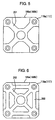
- Fig. 5
- is a plan view of a modification of the pair of brackets,
- Fig. 6
- is a plan view of another modification of the pair of brackets, and
- Fig. 7
- is a sectional view of a conventional hybrid-type stepping motor.
| Conventional Type dB (A) | Invention, Sample 1 dB (A) | Invention, Sample 2 dB (A) | |
| Stepping Motor used alone | 43.5 | 39.6 | 39.6 |
| Stepping Motor mounted in printer for feeding sheets | 59.7 | 56.3 | 56.0 |
Claims (6)
- A stepping motor comprising:a stator (101) including a stator core (107; 200) having a plurality of magnetic poles (108, 109) formed at equiangular intervals on an inner peripheral surface of the stator core (107) in the peripheral direction thereof, each magnetic pole including a support (108) and a toothed portion (109), a winding (110) being placed upon the magnetic poles;a rotor (105) which is inserted into the stator (101) and which is rotatably supported through a pair of bearings (104a, 104b); anda pair of brackets (106a, 106b), respectively fitted to the two axial end portions of the stator core (107);
characterized in thata pair of support members (103a, 103b) are respectively disposed at said two axial end portions of the stator core (107), each support member having an engagement portion (102) engaging an inner peripheral surface of the corresponding one of said end portions;each bracket (106a, 106b) has engagement means (117) engaging an outer peripheral surface of the corresponding one of said end portions, such that the stator core (107) is sandwiched in its radial direction between said engagement portions (102) of the support members (103a, 103b) on the one hand and the engagement means (117) of the brackets (106a, 106b) on the other hand; andthe support members (103a, 103b) and the brackets (106a, 106b) are separate elements in order not to limit the freedom with which the brackets are positioned with respect to the support members in a radial direction thereof. - The motor according to Claim 1, wherein friction reducing means (121) is provided between the surfaces of the brackets (106a, 106b) and the surfaces of the support members (106a, 106b) (103a, 103b) that contact each other in an axial direction thereof.
- The motor according to Claim 1 or Claim 2, wherein a vibration absorbing member is interposed between the surfaces of the brackets (106a, 106b) and the surfaces of the support members (106a, 106b) that contact each other in the axial direction thereof.
- The motor according to any one of Claims 1 to 3, wherein the brackets (106a, 106b) are secured to the stator core (107) with bolts (120), each bolt being positioned such that its axis intersects a line extending from the support of a corresponding one of said magnetic poles radially to the stator core (107).
- The motor according to any one of Claims 1 to 4, wherein the bearings (104a, 104b) are respectively mounted on the support members (103a, 103b).
- The motor according to any one of Claims 1 to 5, wherein one or more ribs (201, 202, 203) for reinforcing the respective engagement means (117) are provided on each of the brackets (106a, 106b).
Applications Claiming Priority (2)
| Application Number | Priority Date | Filing Date | Title |
|---|---|---|---|
| JP00108599A JP3736166B2 (en) | 1999-01-06 | 1999-01-06 | Stepping motor |
| JP108599 | 1999-01-06 |
Publications (3)
| Publication Number | Publication Date |
|---|---|
| EP1018796A2 true EP1018796A2 (en) | 2000-07-12 |
| EP1018796A3 EP1018796A3 (en) | 2001-03-28 |
| EP1018796B1 EP1018796B1 (en) | 2003-10-22 |
Family
ID=11491675
Family Applications (1)
| Application Number | Title | Priority Date | Filing Date |
|---|---|---|---|
| EP99124915A Expired - Lifetime EP1018796B1 (en) | 1999-01-06 | 1999-12-14 | Stepping motor |
Country Status (6)
| Country | Link |
|---|---|
| US (1) | US6249066B1 (en) |
| EP (1) | EP1018796B1 (en) |
| JP (1) | JP3736166B2 (en) |
| CN (1) | CN1135678C (en) |
| DE (1) | DE69912234T2 (en) |
| SG (1) | SG85149A1 (en) |
Cited By (3)
| Publication number | Priority date | Publication date | Assignee | Title |
|---|---|---|---|---|
| EP0957562A3 (en) * | 1998-05-12 | 2001-10-04 | Minebea Co., Ltd. | Stepping motor |
| WO2004086591A1 (en) * | 2003-03-21 | 2004-10-07 | Robert Bosch Gmbh | Electrical machine with a rotor bearing that is integrated inside the stator |
| EP1313199A3 (en) * | 2001-11-16 | 2005-04-27 | Minebea Co., Ltd. | End play adjusting assembly for sealed motor |
Families Citing this family (27)
| Publication number | Priority date | Publication date | Assignee | Title |
|---|---|---|---|---|
| JP4744023B2 (en) * | 2001-07-24 | 2011-08-10 | 日本電産サーボ株式会社 | Permanent magnet 3-phase stepping motor |
| JP4038664B2 (en) * | 2002-06-05 | 2008-01-30 | ミネベア株式会社 | Stepping motor |
| JP2005033860A (en) * | 2003-07-08 | 2005-02-03 | Minebea Co Ltd | Structure of claw-pole stepping motor |
| JP2008278550A (en) * | 2007-04-25 | 2008-11-13 | Japan Servo Co Ltd | Vibration isolation motor |
| JP5134935B2 (en) * | 2007-12-07 | 2013-01-30 | 株式会社日立産機システム | Electric motor |
| JP5171310B2 (en) * | 2008-02-25 | 2013-03-27 | 山洋電気株式会社 | Airtight motor |
| US7755229B2 (en) * | 2008-08-09 | 2010-07-13 | Hiwin Mikrosystem Corp. | Hybrid step motor |
| DE102009024991B4 (en) | 2009-06-16 | 2022-01-13 | Vorwerk & Co. Interholding Gmbh | Electric motor and method for assembling an electric motor |
| US8278803B2 (en) * | 2009-08-14 | 2012-10-02 | Lin Engineering | Motor end cap positioning element for maintaining rotor-stator concentricity |
| CN103546013A (en) * | 2010-06-11 | 2014-01-29 | 日本电产伺服有限公司 | Rotary electric machine |
| US8283841B2 (en) * | 2010-06-23 | 2012-10-09 | Lin Engineering | Motor end cap with interference fit |
| JP5969241B2 (en) * | 2012-03-29 | 2016-08-17 | 株式会社デンソー | Drive device |
| CN102780366A (en) * | 2012-07-23 | 2012-11-14 | 苏州德能电机有限公司 | Novel three-phase asynchronous motor |
| US20140125191A1 (en) * | 2012-11-07 | 2014-05-08 | Lin Engineering | Vibration dampening structure for stepper motors |
| CN103915970B (en) * | 2013-01-09 | 2016-03-16 | 上海鸣志电器股份有限公司 | Composite stepper motor |
| JP6469954B2 (en) * | 2014-03-07 | 2019-02-13 | オリエンタルモーター株式会社 | Hybrid stepping motor |
| CN105546010B (en) * | 2016-01-22 | 2017-06-27 | 山东理工大学 | Three-phase electric excitation biconvex electrode telescopic shock absorber |
| WO2017170297A1 (en) * | 2016-03-31 | 2017-10-05 | 日本電産株式会社 | Motor |
| CN106208454A (en) * | 2016-08-29 | 2016-12-07 | 贵州航天林泉电机有限公司 | A kind of extra small air gap micro-step motor |
| JP6523372B2 (en) | 2017-06-01 | 2019-05-29 | ファナック株式会社 | Electric motor with housing integrated with stator |
| CN109391076A (en) * | 2017-08-08 | 2019-02-26 | 索恩格汽车部件(中国)有限公司 | Motor |
| JP7264717B2 (en) * | 2019-05-15 | 2023-04-25 | ファナック株式会社 | Electric motor with a housing fixed to the end face of the stator core |
| JP7385399B2 (en) * | 2019-08-09 | 2023-11-22 | ミネベアミツミ株式会社 | stepper motor |
| ES3014173T3 (en) * | 2019-12-09 | 2025-04-21 | Dormakaba Deutschland Gmbh | Door assembly with a motor unit having a beneficial basic design |
| FR3121555A1 (en) * | 2021-04-06 | 2022-10-07 | Inteva Products, Llc. | STATOR FOR BRUSHLESS MOTOR OR GENERATOR |
| JP7765996B2 (en) * | 2022-03-23 | 2025-11-07 | 株式会社マキタ | electric work equipment |
| WO2025197090A1 (en) * | 2024-03-22 | 2025-09-25 | ファナック株式会社 | Industrial machine |
Family Cites Families (13)
| Publication number | Priority date | Publication date | Assignee | Title |
|---|---|---|---|---|
| JPS59135087U (en) * | 1983-02-26 | 1984-09-10 | シナノケンシ株式会社 | Permanent magnet step motor |
| JPS6091852A (en) * | 1983-10-20 | 1985-05-23 | Ricoh Elemex Corp | Rotary motor |
| JP2598107B2 (en) * | 1988-10-07 | 1997-04-09 | ファナック株式会社 | Motor bearing structure |
| CA2011025A1 (en) | 1989-03-01 | 1990-09-01 | Terry R. Beardsley | Feline infectious peritonitis vaccine |
| JP3041034B2 (en) | 1990-10-20 | 2000-05-15 | マツダ株式会社 | Liquid-filled engine mount |
| JP3071064B2 (en) * | 1992-04-20 | 2000-07-31 | 日本サーボ株式会社 | Permanent magnet type stepping motor |
| GB2283133B (en) * | 1993-10-20 | 1998-04-15 | Gen Electric | Dynamoelectric machine and method for manufacturing same |
| JPH08298739A (en) * | 1995-04-25 | 1996-11-12 | Minebea Co Ltd | Stepping motor |
| JP3054582B2 (en) | 1995-05-29 | 2000-06-19 | 三洋電機株式会社 | Destination selection method and destination selection device in FM multiplex broadcast receiver |
| JPH1054582A (en) | 1996-08-12 | 1998-02-24 | Corona Corp | Air conditioner |
| JP3399499B2 (en) * | 1997-04-18 | 2003-04-21 | セイコーエプソン株式会社 | Stepping motor |
| US6057613A (en) * | 1998-02-04 | 2000-05-02 | Pacific Scientific Company | Hybrid stepper motor having optimized torque density |
| JP2990432B1 (en) * | 1998-05-12 | 1999-12-13 | ミネベア株式会社 | Stepping motor |
-
1999
- 1999-01-06 JP JP00108599A patent/JP3736166B2/en not_active Expired - Fee Related
- 1999-11-12 SG SG9905649A patent/SG85149A1/en unknown
- 1999-12-14 DE DE69912234T patent/DE69912234T2/en not_active Expired - Lifetime
- 1999-12-14 EP EP99124915A patent/EP1018796B1/en not_active Expired - Lifetime
- 1999-12-16 US US09/468,484 patent/US6249066B1/en not_active Expired - Lifetime
-
2000
- 2000-01-05 CN CNB001009079A patent/CN1135678C/en not_active Expired - Fee Related
Cited By (4)
| Publication number | Priority date | Publication date | Assignee | Title |
|---|---|---|---|---|
| EP0957562A3 (en) * | 1998-05-12 | 2001-10-04 | Minebea Co., Ltd. | Stepping motor |
| EP1313199A3 (en) * | 2001-11-16 | 2005-04-27 | Minebea Co., Ltd. | End play adjusting assembly for sealed motor |
| CN100452620C (en) * | 2001-11-16 | 2009-01-14 | 美蓓亚株式会社 | Sealed structure motor and use method thereof |
| WO2004086591A1 (en) * | 2003-03-21 | 2004-10-07 | Robert Bosch Gmbh | Electrical machine with a rotor bearing that is integrated inside the stator |
Also Published As
| Publication number | Publication date |
|---|---|
| SG85149A1 (en) | 2001-12-19 |
| JP3736166B2 (en) | 2006-01-18 |
| US6249066B1 (en) | 2001-06-19 |
| EP1018796A3 (en) | 2001-03-28 |
| JP2000201468A (en) | 2000-07-18 |
| DE69912234D1 (en) | 2003-11-27 |
| EP1018796B1 (en) | 2003-10-22 |
| DE69912234T2 (en) | 2004-08-05 |
| CN1135678C (en) | 2004-01-21 |
| CN1259790A (en) | 2000-07-12 |
Similar Documents
| Publication | Publication Date | Title |
|---|---|---|
| EP1018796B1 (en) | Stepping motor | |
| JP2742183B2 (en) | Brushless motor | |
| US8823232B2 (en) | Rotary electric machine | |
| CN1298090C (en) | induction motor | |
| JP3364960B2 (en) | Permanent magnet motor rotor | |
| US6710493B2 (en) | Dynamo-electric machine having tapered magnets secured to yoke | |
| JPWO2014170940A1 (en) | Rotor holding structure of rotating electric machine for hybrid vehicle | |
| US6958556B2 (en) | Structure of rotors in stepping motors | |
| JP3624321B2 (en) | Electric motor rotor | |
| US20250015653A1 (en) | Rotor for an outrunner motor and outrunner motor comprising the rotor | |
| CN120677614A (en) | Rotor and method for producing a rotor | |
| KR20130109867A (en) | Motor with rotor for optimizing center of gravity | |
| JP2001298925A (en) | motor | |
| JP7733620B2 (en) | Reluctance rotating electric machine | |
| JP2916394B2 (en) | Electric motor | |
| JPH02207192A (en) | Fan device | |
| JP3298335B2 (en) | Rotating body mounting structure and electric blower using the same | |
| KR200253637Y1 (en) | Brushless Motor with Reduced Vibration | |
| JP2000197335A (en) | Stepping motor | |
| JP2933811B2 (en) | Small motor | |
| JPH06311685A (en) | Frame of rotary electric machine | |
| KR200190464Y1 (en) | Brushless DC Motor | |
| JPH01231631A (en) | Motor | |
| KR20070008172A (en) | Hybrid induction motor | |
| JP2001190040A (en) | Rotor of motor |
Legal Events
| Date | Code | Title | Description |
|---|---|---|---|
| PUAI | Public reference made under article 153(3) epc to a published international application that has entered the european phase |
Free format text: ORIGINAL CODE: 0009012 |
|
| AK | Designated contracting states |
Kind code of ref document: A2 Designated state(s): DE FR GB |
|
| AX | Request for extension of the european patent |
Free format text: AL;LT;LV;MK;RO;SI |
|
| PUAL | Search report despatched |
Free format text: ORIGINAL CODE: 0009013 |
|
| AK | Designated contracting states |
Kind code of ref document: A3 Designated state(s): AT BE CH CY DE DK ES FI FR GB GR IE IT LI LU MC NL PT SE |
|
| AX | Request for extension of the european patent |
Free format text: AL;LT;LV;MK;RO;SI |
|
| RIC1 | Information provided on ipc code assigned before grant |
Free format text: 7H 02K 5/15 A, 7H 02K 5/04 B, 7H 02K 5/24 B, 7H 02K 5/167 B |
|
| 17P | Request for examination filed |
Effective date: 20010302 |
|
| AKX | Designation fees paid |
Free format text: DE FR GB |
|
| GRAH | Despatch of communication of intention to grant a patent |
Free format text: ORIGINAL CODE: EPIDOS IGRA |
|
| GRAS | Grant fee paid |
Free format text: ORIGINAL CODE: EPIDOSNIGR3 |
|
| GRAA | (expected) grant |
Free format text: ORIGINAL CODE: 0009210 |
|
| AK | Designated contracting states |
Kind code of ref document: B1 Designated state(s): DE FR GB |
|
| REG | Reference to a national code |
Ref country code: GB Ref legal event code: FG4D |
|
| REF | Corresponds to: |
Ref document number: 69912234 Country of ref document: DE Date of ref document: 20031127 Kind code of ref document: P |
|
| ET | Fr: translation filed | ||
| PLBE | No opposition filed within time limit |
Free format text: ORIGINAL CODE: 0009261 |
|
| STAA | Information on the status of an ep patent application or granted ep patent |
Free format text: STATUS: NO OPPOSITION FILED WITHIN TIME LIMIT |
|
| 26N | No opposition filed |
Effective date: 20040723 |
|
| PGFP | Annual fee paid to national office [announced via postgrant information from national office to epo] |
Ref country code: GB Payment date: 20141210 Year of fee payment: 16 Ref country code: DE Payment date: 20141209 Year of fee payment: 16 |
|
| PGFP | Annual fee paid to national office [announced via postgrant information from national office to epo] |
Ref country code: FR Payment date: 20141208 Year of fee payment: 16 |
|
| REG | Reference to a national code |
Ref country code: DE Ref legal event code: R119 Ref document number: 69912234 Country of ref document: DE |
|
| GBPC | Gb: european patent ceased through non-payment of renewal fee |
Effective date: 20151214 |
|
| REG | Reference to a national code |
Ref country code: FR Ref legal event code: ST Effective date: 20160831 |
|
| PG25 | Lapsed in a contracting state [announced via postgrant information from national office to epo] |
Ref country code: DE Free format text: LAPSE BECAUSE OF NON-PAYMENT OF DUE FEES Effective date: 20160701 Ref country code: GB Free format text: LAPSE BECAUSE OF NON-PAYMENT OF DUE FEES Effective date: 20151214 |
|
| PG25 | Lapsed in a contracting state [announced via postgrant information from national office to epo] |
Ref country code: FR Free format text: LAPSE BECAUSE OF NON-PAYMENT OF DUE FEES Effective date: 20151231 |