EP1021003B1 - Réseau sans fil - Google Patents
Réseau sans fil Download PDFInfo
- Publication number
- EP1021003B1 EP1021003B1 EP00200074A EP00200074A EP1021003B1 EP 1021003 B1 EP1021003 B1 EP 1021003B1 EP 00200074 A EP00200074 A EP 00200074A EP 00200074 A EP00200074 A EP 00200074A EP 1021003 B1 EP1021003 B1 EP 1021003B1
- Authority
- EP
- European Patent Office
- Prior art keywords
- channel
- base station
- terminal
- terminals
- signaling
- Prior art date
- Legal status (The legal status is an assumption and is not a legal conclusion. Google has not performed a legal analysis and makes no representation as to the accuracy of the status listed.)
- Expired - Lifetime
Links
- 230000011664 signaling Effects 0.000 claims description 144
- 238000001514 detection method Methods 0.000 claims description 53
- 230000005540 biological transmission Effects 0.000 description 30
- 238000000034 method Methods 0.000 description 14
- 230000006870 function Effects 0.000 description 8
- 230000007480 spreading Effects 0.000 description 7
- PCHJSUWPFVWCPO-UHFFFAOYSA-N gold Chemical compound [Au] PCHJSUWPFVWCPO-UHFFFAOYSA-N 0.000 description 6
- 239000010931 gold Substances 0.000 description 6
- 229910052737 gold Inorganic materials 0.000 description 6
- 108010003272 Hyaluronate lyase Proteins 0.000 description 5
- 230000001360 synchronised effect Effects 0.000 description 5
- 238000012790 confirmation Methods 0.000 description 4
- 238000010586 diagram Methods 0.000 description 3
- 238000011156 evaluation Methods 0.000 description 3
- 101000579423 Homo sapiens Regulator of nonsense transcripts 1 Proteins 0.000 description 2
- 102100028287 Regulator of nonsense transcripts 1 Human genes 0.000 description 2
- 230000008901 benefit Effects 0.000 description 2
- 230000008859 change Effects 0.000 description 2
- 230000000694 effects Effects 0.000 description 2
- 230000010365 information processing Effects 0.000 description 2
- 238000005259 measurement Methods 0.000 description 2
- 238000010295 mobile communication Methods 0.000 description 2
- 238000001208 nuclear magnetic resonance pulse sequence Methods 0.000 description 2
- 230000008569 process Effects 0.000 description 2
- 238000012545 processing Methods 0.000 description 2
- 230000007704 transition Effects 0.000 description 2
- 108010076504 Protein Sorting Signals Proteins 0.000 description 1
- 238000005311 autocorrelation function Methods 0.000 description 1
- 238000004891 communication Methods 0.000 description 1
- 239000007799 cork Substances 0.000 description 1
- 230000001934 delay Effects 0.000 description 1
- 230000001419 dependent effect Effects 0.000 description 1
- 230000009365 direct transmission Effects 0.000 description 1
- 239000000284 extract Substances 0.000 description 1
- 230000002452 interceptive effect Effects 0.000 description 1
- 238000012805 post-processing Methods 0.000 description 1
- 238000011895 specific detection Methods 0.000 description 1
- 238000001228 spectrum Methods 0.000 description 1
- 230000003068 static effect Effects 0.000 description 1
- 230000002123 temporal effect Effects 0.000 description 1
- 238000012360 testing method Methods 0.000 description 1
- 230000001960 triggered effect Effects 0.000 description 1
- 238000002604 ultrasonography Methods 0.000 description 1
Images


Classifications
-
- H—ELECTRICITY
- H04—ELECTRIC COMMUNICATION TECHNIQUE
- H04B—TRANSMISSION
- H04B7/00—Radio transmission systems, i.e. using radiation field
- H04B7/24—Radio transmission systems, i.e. using radiation field for communication between two or more posts
- H04B7/26—Radio transmission systems, i.e. using radiation field for communication between two or more posts at least one of which is mobile
- H04B7/2628—Radio transmission systems, i.e. using radiation field for communication between two or more posts at least one of which is mobile using code-division multiple access [CDMA] or spread spectrum multiple access [SSMA]
-
- H—ELECTRICITY
- H04—ELECTRIC COMMUNICATION TECHNIQUE
- H04B—TRANSMISSION
- H04B1/00—Details of transmission systems, not covered by a single one of groups H04B3/00 - H04B13/00; Details of transmission systems not characterised by the medium used for transmission
- H04B1/69—Spread spectrum techniques
- H04B1/707—Spread spectrum techniques using direct sequence modulation
- H04B1/709—Correlator structure
- H04B1/7093—Matched filter type
-
- H—ELECTRICITY
- H04—ELECTRIC COMMUNICATION TECHNIQUE
- H04B—TRANSMISSION
- H04B2201/00—Indexing scheme relating to details of transmission systems not covered by a single group of H04B3/00 - H04B13/00
- H04B2201/69—Orthogonal indexing scheme relating to spread spectrum techniques in general
- H04B2201/707—Orthogonal indexing scheme relating to spread spectrum techniques in general relating to direct sequence modulation
- H04B2201/70701—Orthogonal indexing scheme relating to spread spectrum techniques in general relating to direct sequence modulation featuring pilot assisted reception
-
- H—ELECTRICITY
- H04—ELECTRIC COMMUNICATION TECHNIQUE
- H04J—MULTIPLEX COMMUNICATION
- H04J13/00—Code division multiplex systems
- H04J13/0007—Code type
- H04J13/0022—PN, e.g. Kronecker
- H04J13/0029—Gold
-
- H—ELECTRICITY
- H04—ELECTRIC COMMUNICATION TECHNIQUE
- H04W—WIRELESS COMMUNICATION NETWORKS
- H04W72/00—Local resource management
- H04W72/20—Control channels or signalling for resource management
- H04W72/21—Control channels or signalling for resource management in the uplink direction of a wireless link, i.e. towards the network
Definitions
- the invention relates to a wireless network with at least one base station and a plurality of associated terminals for exchanging user and control data.
- the radio network consists of nichreren radio cells, each with a base station and located therein terminals or mobile stations. For example, after registering and synchronizing a terminal, upon request of a payload channel, a terminal sends a random access burst message over a Random Access Channel (RACH).
- RACH Random Access Channel
- the message packet consists of a preamble part and a data part.
- the preamble part consists of 16 orthogonal symbols (preamble sequence), which is spread by a gold code (preamble code / preamble code).
- the gold code contains 256 chip intervals.
- the data part contains a field with an identifier for the terminal, a field for identifying the requested service (short packet transmission, dedicated-channel set-up connection request, etc.), an optional field for data packets ( Optional user packet) and a CRC field for fault detection.
- a message packet received from a base station is supplied via a matched filter, a preamble correlator, a peak detector to a circuit portion estimating the timing of the data portion, which controls a RAKE circuit for evaluating the data portion.
- a correlation-based pulse detection with subsequent message decoding is used here.
- WO98 / 18289 describes a mobile radio system with a base station and a plurality of mobile stations, For channel capacity request, a mobile phone sends an Access Request Data Frame at the beginning of a random access frame. Before that, the mobile station is already synchronized with the base station. The mobile station determines the start time for each random access frame from a broadcast / pilot channel information broadcast by the base station. After the "Access Request Frame" is received and demodulated with a matched filter, the base station recognizes the request and controls the subsequent information transmissions of the mobile station. If channel capacities are available, the base station transmits a confirmation message to the mobile station. If no channel capacities are available, the base station transmits a "busy" message.
- a mobile station indicates a channel capacity request on the random access channel. To avoid collisions with simultaneous channel capacity requirements, repetitions of the random access signal from two mobile stations are stretched or the number of repetitions is reduced. These parameters, which indicate the number of repetitions and the intervals between repetitions, are broadcasted on the BCCH channel. Thus, the parameters are the same for all mobile stations.
- the invention has for its object to provide a wireless network in which a terminal exchanges signaling information with the associated base station in a different way.
- a wireless network having at least one base station and a plurality of associated terminals for exchanging payload and control data, in which the terminals for channel capacity request emit a signaling sequence, and the base station has a correlation device for correlation of a signal transmitted by one of the assigned terminals comprising the signaling sequence, wherein the correlation device is used for detecting a pulse resulting from the signaling sequence and the base station includes a channel access control provided after detection of the signaling sequence for rejecting or acknowledging the channel capacity requirement of the terminal for a shared channel of multiple terminals, wherein the base station includes means for providing to the associated terminals different start times within a reference frame for transmitting at least one signaling allocate for a channel capacity request.
- the wireless network is to be understood as meaning a network with a plurality of radio cells, in each of which one base station and a plurality of terminals transmit control and user data wirelessly.
- a wireless transmission is used to transmit information e.g. via radio, ultrasound or infrared paths.
- a terminal for transmitting user data must request a specific traffic channel at the assigned base station.
- a traffic channel may be, for example, a dedicated traffic channel (eg for voice transmission) either between the base station and the terminal or between two terminals.
- the assignment of the channels is carried out by the base station.
- a request, for example, for a dedicated traffic channel is transmitted from a terminal via a signaling channel predetermined by the base station. From the base station at least the start time of a possibly previously known signaling sequence must Terminals are communicated. It is also possible that apart from the start time, the terminals are also assigned one of several signaling sequences.
- a signaling sequence is a gold or Kasami sequence with good auto and cross-correlation properties.
- the base station contains a device (eg a matched filter) in which a correlation of the received signaling sequences is carried out.
- the resulting from the correlation pulse is detected and assigned to a terminal. Since a collision is avoided in the network according to the invention by different start times of the signaling sequences and no message decoding is performed according to a correlation-based pulse detection, but the appearance of the pulse resulting from the signaling sequence is regarded as a signaling request, signaling detection can be more robust and robust, especially at high traffic loads be performed faster than in the prior art.
- a specific time range for pulse detection is selected as a function of the start time of the signaling sequence and of the channel properties.
- Such a time range is referred to as a detection window.
- the length or duration and the start time of the detection window must be selected so that an impulse detection is possible.
- the detection windows are smaller than the time duration of the message packets known from the prior art. With the signaling according to the invention, therefore, many terminals within a short time range can issue a signaling request.
- a terminal in a radio cell always has the same starting time with respect to a reference frame after the registration and synchronization for the transmission of a signaling sequence, as long as the base station does not explicitly change this starting time.
- a signaling channel is initially permanently occupied for a terminal. Since many such start times may be included in the reference frame which is of short duration (eg 10 ms) and since all terminals of a radio cell use the same signaling sequence, only a small amount of network resources are consumed in the permanent assignment of a start time and a signaling sequence to a terminal ,
- the signaling sequences of all terminals in a radio cell have different start times. In the simplest case, the same signaling sequences are used by each terminal. The signaling sequences can therefore be partially overlaid, since the length of a sequence is usually longer than the distance of two consecutive start times.
- An advantage of the network according to the invention is also the security of the recognition of a signaling request.
- a detectable pulse is almost always generated after the transmission of a signaling sequence. This is because spurious signals and channel noise can lead to "artificial" pulses at the output of the matched filter. It is very unlikely that these will reduce the amplitude of the pulses at the output of the matched filter upon receipt of an actual transmitted signaling sequence. In the worst case (for example, in the case of disturbances), a false alarm is thus triggered if the amplitude of the noise or interference signal exceeds the detection threshold without a signaling sequence having been sent.
- the signaling sequence can also be used to request channel capacity of a shared channel (shared uplink channel).
- the base station upon receipt of a signaling sequence, either rejects a request or acknowledges the request of a terminal for channel capacity in a channel shared by multiple terminals. Using a shared channel results in a capacity increase due to static effects.
- the acknowledgment or rejection of a channel capacity for at least one terminal transmits the base station to the relevant terminal via an allocation control channel.
- the base station transmits further information concerning the transmission of the payload data over the shared channel. Such information may relate to the start time of the transmission of the user data, the data rate, the transmission power, the spreading factor, etc.
- the shared channel can be used eg by 8 terminals for the transmission of user data. If another terminal wants to use this channel, This terminal sends out another specific signaling sequence.
- the base station checks whether the terminal can be included in the group of the channel shared by several terminals. If the test result is positive, the base station notifies the relevant terminal that it will be included in the group.
- Fig. 1 is a wireless network, such as a wireless network, with multiple base stations 1 to 3 and multiple terminals 4 to 14 shown.
- a base station 1 to 3 are assigned to certain terminals 4 to 14.
- the base station 1 to 7 the base station 2, the terminals 8 to 10 and the base station 3, the terminals 11 to 14 assigned.
- a control data exchange takes place at least between the base station and the terminals.
- a user data exchange can be carried out both between the base station and the terminals and directly between the terminals. In both cases, the base station establishes the connection for transmitting user data.
- the terminals 4 to 14 are usually mobile stations, which are controlled by a fixed base station 1 to 3. If appropriate, a base station 1 to 3 can also be mobile or mobile.
- radio signals are transmitted by the FDMA, TDMA or CDMA (Frequency Division Multiplex Access) (TDMA) method or by a combination of the methods.
- FDMA Frequency Division Multiplex Access
- CDMA Frequency Division Multiplex Access
- a user-originated binary information is modulated with a different code sequence each time.
- a code sequence consists of a pseudo-random square-wave signal (pseudo noise code) whose rate, also called chip rate, is generally much higher than that of the binary information.
- the duration of a rectangular pulse of the pseudorandom square wave signal is referred to as the chip interval T C. 1 / T C is the chip rate.
- the base stations are assigned to certain radio cells in which the data traffic is handled with each located in the radio cell terminals. If a terminal moves from one radio cell to another radio cell, the assignment of the terminal from one to the other base station is handled according to certain specifications. At the same time, this terminal can exchange data with the base stations of the two radio cells during the transition from one radio cell to another. This is called soft handover.
- a radio cell is in Fig. 1 indicated by a dashed circle.
- User data and control data between at least one terminal and one base station are transmitted via channels predetermined by the base station.
- the radio connection from the base station to the terminals is referred to as downlink and from the terminals to the base station as uplink.
- data is transmitted via downlink channels from the base station to the terminals and over the uplink channels from terminals to the base station.
- a downlink control channel may be provided which is used to distribute control data from the base station to all terminals prior to establishing a connection.
- Such a channel is called a downlink distribution control channel.
- an uplink control channel assigned by the base station can be used, but to which other terminals can also access.
- An uplink channel that can be used by multiple or all terminals is referred to as a common uplink channel.
- payload data are transmitted via a downlink and an uplink traffic channel.
- channels called peer-to-peer payload channels are used.
- Channels that are established only between a transmitter and a receiver are referred to as dedicated channels.
- a traffic channel is a dedicated channel that can be accompanied by a dedicated control channel for transmission of connection-specific control data.
- a channel is characterized by a frequency range, a time range and e.g. determined by a spreading code in the CDMA method.
- the terminal For user data to be exchanged between the base station and a terminal, it is necessary for the terminal to be synchronized with the base station.
- GSM Global System for Mobile Communication
- the temporal position of a frame is determined on the basis of predefined parameters after the determination of a suitable frequency range ( Frame synchronization), with the aid of which the time sequence for the transmission of data takes place.
- a suitable frequency range Frame synchronization
- Such a framework is always necessary for the data synchronization of terminals and base station in TDMA, FDMA and CDMA methods.
- Such a frame may contain various subframes or subframes or form a superframe with several other consecutive frames. For reasons of simplification, the following is based on a frame which is referred to as a reference frame.
- the pulse duration is exactly the same as the time interval required to transmit one bit.
- the pulse duration corresponds to a chip interval.
- One bit interval corresponds to several chip intervals.
- the transmission of a special pulse sequence by the base station is required.
- the start time of the pulse sequence corresponds to the start time of a frame.
- a terminal eg one of the terminals 4 to 7 in Fig. 1
- this must be for transmission a traffic channel for a downlink and an uplink connection or a peer-to-peer traffic channel from the associated base station (eg base station 1 in Fig. 1 ) to provide.
- the base station eg the base station 1 in Fig. 1
- the associated terminals eg, terminals 4 to 7
- a downlink broadcast control channel during arbitrary frame control data.
- Such a signaling sequence transmitted by a terminal is a pseudo-random square-wave signal and indicates that this terminal requests a traffic channel.
- Each terminal is therefore assigned an uplink signaling channel for transmitting a signaling sequence from the base station, via which signaling sequences are transmitted.
- the base station can perform the allocation of the signaling sequence and the sequence start time for each terminal only once. This can happen, for example, during the registration of a terminal at the associated base station.
- the assignment of the sequence start times can also - as will be explained below - depending on the different channel characteristics of the connections between the base station and terminals done.
- a signaling channel is realized in the invention by the particular signaling sequence and its start time.
- All terminals assigned to a base station transmit the same signaling sequence but at different times (sequence start times). Consequently, different base stations assign different signaling sequences to their assigned or registered terminals. However, it is sufficient if only the neighboring base stations each have different signaling sequences. For example, if a terminal is registered with a transition from one radio cell to another at two base stations, it sends out the signaling sequence that the base station from which a traffic channel is requested.
- a base station includes a single matched filter and a downstream pulse detector for detecting the signaling sequences transmitted by the terminals.
- the matched filter is clocked at a clock rate that is at least equal to the maximum chip rate when using a code spread or equal to the maximum bit rate when no code spread is used. From the terminals such signaling sequences are sent out, which have a good autocorrelation property. This means that the pulses resulting from the successive signaling sequences of different terminals at the output of the matched filter can be unambiguously detected by the pulse detector within a detection window.
- the choice of clock rate as a function of the maximum chip rate and a signaling sequence with good autocorrelation properties allows the successive signaling sequences to have a minimum time interval between their start times.
- the signaling sequence should have a good cross-correlation property, ie the correlation to other signals transmitted in the network should be low.
- the other signals transmitted in the network and received by the matched filter are interpreted by the pulse detector as a negligible noise signal and, on the other hand, the signaling sequences of other circuit elements in the base station which process the other signals transmitted in the network are interpreted as negligible noise .
- Such a signaling sequence with good auto and cross-correlation properties is for example the one from the book " JG Proakis: Digital Communications by JG Proakis, Third Edition, McGraw-Hill International Editions, 1995, pages 724-729 "known sequence of gold and Kasami.
- the resulting at the output of the matched filter pulses are a measure of the energy of the signaling sequences.
- the sequence start time of a signaling sequence should be set by the base station so that the matched filter in the base station generates a pulse after the detection of a signaling sequence of a terminal assigned to it in a predetermined detection window.
- This detection window has the duration or length ⁇ .
- the signaling sequences can be sent out at any sequence start times.
- a sequence start time is associated with the occurrence of a pulse at the output of the matched filter.
- the detection begins after transmission of a signaling sequence and a delay caused by the channel characteristic of a connection between at least one terminal and a base station.
- the channel characteristic is the physical characteristic of a channel.
- a channel property results, for example, from the distance between the terminal and the base station. Consequently, it is possible for the pulse detector to use different width detection windows for the various terminals. For the sake of simplicity, a uniform width of the detection window is selected here.
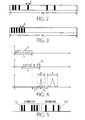
- the sequence of arbitrarily occurring detection windows of duration ⁇ is with respect to the reference frame of length FR in Fig. 2 shown.
- the matched filter usually generates from a received signaling sequence a pulse train having a main pulse and a plurality of secondary pulses often distributed symmetrically around the main pulse.
- the amplitude of the secondary pulses is regularly smaller than the amplitude of the main pulse.
- the various main pulses generated by the matched filter must have a guard time so that the channel-skewed pulse trains of the different terminals appearing at the output of the matched filter do not overlap so that unambiguous detection becomes impossible. With a certain overlap, the base station can not uniquely assign the pulses to a terminal.
- the width or duration ⁇ of the detection window must therefore be at least equal to the main pulse width, which results without channel influence, and an additional channel-dependent safety interval. This also results in the spacing of successive, identical signaling sequences.
- an optimized distance of the sequence start times can be provided according to the invention. This means that in each case the width of the detection window is determined as a function of the channel properties between a terminal and the base station. Another possibility according to the invention that is easier to implement is that the signaling sequences are transmitted successively at a constant distance. When determining the constant distance, the worst channel properties must be considered.
- Fig. 3 shows the continuously successive detection windows with respect to the reference frame of length FR, which result as a consequence of the signaling sequences transmitted at a predetermined constant distance.
- Fig. 4 Two exemplary signaling sequences S 1 and S 2 are shown, which have the sequence duration or sequence length L 1 and L 2 . After a delay time p 1 and p 2 caused by the channel properties, the detection process or the detection window of length ⁇ respectively starts. In such a detection window, a main pulse and secondary pulses assigned to a signaling sequence appear.
- the length ⁇ of the detection window is determined in particular by three factors (channel properties). First, the accuracy of estimating the propagation delay of the data to be transmitted from the terminals to the base station, secondly the delay spread characteristic due to multiple propagation and thirdly the autocorrelation properties of the signaling sequences terminals are considered.
- the terminals are usually at different distances from the base station. This leads to different propagation delays of the signaling sequences emitted by the terminals.
- the propagation delay between the terminal MT i and the base station B should be equal to p i and the length of the signaling sequence equal to L.
- the base station When the base station expects a pulse for the terminal MT i at the output of the matched filter at time t i , it instructs the terminal MT to begin transmitting the signaling sequence at time t 1 -p i -L.
- the pulse at the output of the matched filter is inaccurate. This inaccuracy in the estimation of the propagation delay p i must be compensated by a sufficiently long detection window ⁇ . If the maximum uncertainty in the estimate is j for all terminals, the detection window must be greater than j.
- the data between a terminal and a base station are usually transmitted not only over one radio path but over several (multiple propagation). Due to reflection and diffraction effects, the signal transmitted from a terminal to the base station passes through various paths and the resulting multi-path signals are received by the base station at different times. This results in the output of the matched filter for a signaling sequence not only a single main pulse, but appear at the output of the matched filter other main pulses. These further main impulses are produced at the output of the matched filter by signals which have arisen due to the multiple propagation and which are grouped around the actual main impulse. The actual main pulse is produced at the output of the matched filter from the received actual signaling sequence.
- the length ⁇ of the detection window must be greater than a window of length w, which contains the actual main pulse and the other main pulses. It should be noted that even without multiple propagation at the output of the matched filter not only an actual main pulse, but also secondary pulses appear. However, the amplitude of the sub-pulses is much smaller than the amplitude of the main pulse due to the good autocorrelation properties described above.
- the autocorrelation property of the signaling sequence is the measure of the width of the main pulse and the minima and maxima of the sub-pulses at the output of the matched filter (ignoring the channel characteristics).
- the main pulse at the output of the matched filter is approximately equal to the energy of the signaling sequence.
- the amplitude of the main pulse is much larger than that of the secondary pulses.
- the energy of the signaling sequence is thus determined by its amplitude and duration or length.
- the signaling sequence e.g., gold or Kasami sequence
- the signaling sequence should have a significantly lower amplitude than the other signals.
- the signaling sequence must be sufficiently long.
- the detection duration of a signaling sequence and thus the assignment of user channels of the base station to the terminal are extended.
- the length of a signaling sequence affects both the autocorrelation property of the signaling sequence and the signaling time. For a given signaling sequence, if the autocorrelation function is sufficiently large within a time interval q, ⁇ must be greater than q.
- the duration ⁇ of the detection window is dimensioned so that only a single signaling sequence can be detected.
- a base station receives binary information or 1-bit information.
- This binary information indicates whether a terminal which has transmitted the signaling sequence requests a new traffic channel (pulse at the output of the matched filter during the duration of the detection window) or no traffic channel (pulse at the output of the matched filter during the duration of the Detection window not available).
- the following is the extension of transmission from 1-bit to n-bit information (n> 1, n is an integer).
- a terminal sends the same signaling sequence not once but several times in succession per reference frame to provide the base station n-bit information available.
- n-bit information is achieved by extending the detection window by increasing the duration or length of the detection window for each affected terminal by a factor of n.
- n signaling sequences of a terminal can be detected during the occurrence of the n-times enlarged detection window.
- the terminal which transmits an n-bit information (signaling data), uses identical signaling sequences whose start times are shifted by the value ⁇ in each case.
- a transmitted signaling sequence then indicates, for example, a "1" and a non-transmitted signaling sequence a "0".
- FIG. 5 an example of the position of pulses detected from identical signaling sequences is shown.
- a first group G1 of pulses is signaling sequences of a first terminal and a second group G2 of pulses is associated with signaling sequences of a second terminal.
- the first group G 1 yields the 7-bit information "1100111" and the second group G2 the information "0100101".
- the information "001" may mean that the terminal requests an 8 kbit / s traffic channel.
- the information "001" is generated by two not emitted and one emitted signaling sequence.
- the desire for a 64 kbit / s traffic channel of a terminal may be expressed by the information "010" and the desire for a 144 kbit / s traffic channel of a terminal may be expressed by the information "011".
- the matched filter in the base station is hereby intended to receive both 1-bit and n-bit information, since in both cases the same signaling sequence is received. In the two cases, only the post-processing of the pulses detected by the matched filter differs. An information processing will in the first case after the duration ⁇ for the detection of a signaling sequence and in the second case after the duration n ⁇ for the detection of n signaling sequences.
- the number of signaling channels of a base station using a single signaling sequence is limited to the value FR / ⁇ , where FR is the length of the reference frame and ⁇ is the length of a detection window.
- FR is the length of the reference frame
- ⁇ is the length of a detection window.
- each detection window is the same length and has the length ⁇ .
- a base station wants to allocate more signaling channels than given by the value FR / ⁇ , it can assign to the terminals not only a single but different signaling sequences. For example, during a reference frame 100, identical signaling sequences can be detected by the matched filter. But are they e.g.
- 120 terminals in the radio cell that want to send a signaling sequence it is not possible that all these 120 terminals use the same signaling sequence. Therefore, e.g. 60 terminals transmit a first and the other 60 terminals a second signaling sequence, which can then be detected by two different matched filters in the base station. It should also be mentioned that the sequence start times of the different signaling sequences are independent of one another, that is, coordination with one another is not necessary. Only the start times of the same signaling sequences must be coordinated.
- UMTS Universal Mobile Telecommunication System
- a recipient Fig. 6
- a transmitter Fig. 7
- a receiver Fig. 8
- a transmitter Fig. 9
- FIG. 6 shown block diagram of a receiver of a base station contains as known Elements (eg from the GSM mobile radio system or a CDMA system) an antenna 15, a high-frequency block 16, an intermediate frequency block 17, an analog-to-digital converter 18, a demodulator 19 and a block 20, for example, the switching functions channel demultiplexing, deinterleaving, channel decoding and also performs despreading using a CDMA system.
- the baseband control and payload signals are applied to a channel access control block 23, which forwards the various signals to the appropriate units for further processing, such as a central office.
- a matched filter 21 is inserted into the receiver of the base station, which checks the received signals for the presence of a signaling sequence.
- a signaling sequence has been detected during the expected time period (detection window), ie at least one pulse is generated, this is detected by a subsequent pulse detector 22 and reported to the channel access control block 23, which may be a processor, for example.
- the channel access control block 23 forwards this message to downstream further control elements, not shown here, which then assign a user channel to the terminal, for example by means of generated control data via the transmitter of the base station.
- the duration or length ⁇ of the detection window may be fixed and determined for example by measurements before the normal operation of the network. It is also possible to determine the duration ⁇ of the detection window for each terminal individually during operation.
- the duration ⁇ of the detection window for a specific signaling sequence and of a terminal is supplied in this case by a control element, not shown here, to the pulse detector after the evaluation of measurement results.
- the distance between a base station and a terminal is evaluated on the basis of the signals received by the terminal in the base station.
- the information processing of the pulses generated by the matched filter 21 detected by the pulse detector 22 is performed in the channel access control block 23.
- a specific detection window is assigned to a terminal. If at least one main pulse is detected in such a detection window, the channel access control block 23 determines that there is a request from the terminal for a useful channel. From this request and inquiries of other terminals and considering the existing connections or the granting user channels, decides a control not shown in detail after receiving the request from the channel access control block 23, whether the requesting terminal, a traffic channel can be provided. If an allocation of a user channel is possible, this user channel is determined and after processing in the transmitter of the base station ( Fig. 7 ) is supplied to the terminal via a downlink distribution control channel.
- the base station transmitter also includes a channel access control block 24 which receives data from various sources 25.
- a source may be, for example, an exchange providing user data or a control element which supplies control data.
- these control data may contain information about a useful channel to be used for a terminal which has previously requested a user channel by means of a signaling sequence.
- the control block 24 subsequent block 26, for example, performs the switching functions channel coding, interleaving, channel multiplexing and when using a CDMA system also a spreading.
- the output of the block 26 is passed through a modulator 27, a digital-to-analog converter 28, an intermediate frequency block 29 and a high frequency block 30 to an antenna 31. All elements 25 to 31 may be elements known from existing mobile radio systems.
- FIG. 8 A block diagram of a receiver of a terminal is shown Fig. 8 ,
- This receiver contains, as elements known for example from the GSM mobile radio system or a CDMA system, an antenna 32, a radio frequency block 33, an intermediate frequency block 34, an A / D converter 35, a demodulator 36, a block 37 with different functions and a channel access control block 38, the control and user data to various sinks (eg, low frequency circuit for converting user data in voice data).
- the block 37 is responsible, for example, for the switching functions channel demultiplexing, deinterleaving, channel decoding and when using a CDMA system for despreading.
- the channel access control block 38 evaluates certain channels relevant to the terminal, such as a payload channel or a downlink distribution control channel.
- Circuit element passed in the terminal.
- the channel access block 38 extracts, for example, the information to which start time, at least one signaling sequence can be sent out. This information is passed to at least one circuit element not shown here.
- the terminal contains in its transmitter, its associated block diagram in Fig. 9 Also shown is a channel access control block 39 that controls a channel access.
- the channel access control block 39 provides a block 42 which performs, for example, the switching functions channel coding, interleaving, channel multiplexing and also spreading using a CDMA system.
- the channel access control block 39 indicates to a timer 40 the start timing of a signaling sequence.
- the payload and control data are obtained from the channel access control block 39 from various sources.
- a source may be, for example, a low-frequency circuit which supplies voice data as payload data, or a control element which supplies control data.
- this control data may be information about the start time of a signaling sequence.
- the timing controller 40 provides timestamps to a generator 41 to generate a signaling sequence.
- the time stamps may be, for example, the start and end times of rectangular pulses of the signaling sequence.
- the generator contains a memory for storing various signaling sequences.
- the signaling sequence to be transmitted is selected by the channel access control block. If appropriate, signaling sequences can be written into the memory of the generator 41.
- the generator 41 and the timing element 40 are initialized upon receipt of the information about the signaling sequence to be used and the start time of the signaling sequence. If no change in signaling sequence and / or start time is indicated by the associated base station, further initialization of generator 41 and timing element 40 is not required.
- the useful and control data processed in block 42 are supplied to a superposition circuit 43 which still receives the output signals of the generator 41.
- the output from the superposition circuit 43 output signal is transmitted via a modulator 44, a digital-to-analog converter 45, an intermediate frequency block 46 to a high-frequency block 47, by means of an antenna 48 in the High frequency block emitted signals.
- a signaling sequence transmitted by a terminal is used to request a traffic channel from the associated base station. This is usually a dedicated channel. This request occurs after a terminal has been synchronized with and registered with the base station.
- the signaling sequence may also be used to request a shared uplink channel for transmission of packets.
- a shared uplink traffic channel is a channel for simultaneously transmitting payload data from multiple terminals to the base station. For example, 8 terminals designated by the base station can simultaneously use this channel.
- a signaling sequence is sent from a terminal to a start time specified by the base station, this means requesting a certain capacity (e.g., 16 kbit / s) of the channel for transmission of payload data.
- the base station transmits a confirmation or rejection of the reservation of channel capacity via a special control channel called the Access Control Channel.
- the terminal With the confirmation of the capacity reservation, the terminal is still informed via the allocation control channel various information necessary for the transmission of the user data. If a CDMA method is used to transmit the payload data, the allocation control channel is used to transmit to the terminal the start time of the transmission of the payload data, the data rate, the transmission power and the spreading factor for the shared uplink traffic channel. After the terminal has received the information about the start time and the spreading factor, the terminal starts to transmit the user data packed in packets.
- the base station defines a certain number of terminals (eg 8) that can use the shared uplink traffic channel to transmit packetized payload data.
- a terminal that is not yet a user of this shared uplink traffic channel may look for a corresponding one Requirement as a new user of the channel from the base station will be determined.
- either another terminal, which is previously part of the group of terminals using the shared uplink traffic channel can be removed for the new terminal, or the new terminal can be added in addition to the group if the channel capacity still has free resources. Care must be taken to ensure that the interference generated within the system is not exceeded by the addition of the terminal. For example, if a terminal is to be removed, the terminal will be removed from the base station if that terminal has no longer requested any channel capacity for the shared uplink traffic channel (that is: transmission power for particular data rate, time slot, spreading factor, carrier frequency).
- a terminal wishing to become a user of the shared uplink payload channel sends a signaling sequence at a start time determined by the base station. This start time may be known to the terminals or is communicated from the base station to the terminal each after it has been sent via a e.g. collision-prone channel has requested the start time.
- the base station Upon receipt of the signaling sequence, the base station checks to see if any one of the group of terminals using the shared uplink traffic channel needs to be removed. If so, the two terminals concerned are informed via the allocation control channel that one terminal has been removed from the group and another has been taken. Otherwise, the allocation control channel only informs that a new terminal has been added to the group.
- the advantage of displaying a signaling sequence for the request for channel capacity in the shared uplink control channel or for the request to be included in the group of terminals using the shared uplink control channel is that no collision can occur. Further, by having a shared uplink control channel e.g. is used to transmit payload data in packets, instead of various dedicated payload channels, a capacity increase due to statistical multiplexing effects takes place. The fact that the base station notifies the terminals of the transmission power for the transmission of the user data, the interference of the system can be better controlled.
Landscapes
- Engineering & Computer Science (AREA)
- Computer Networks & Wireless Communication (AREA)
- Signal Processing (AREA)
- Mobile Radio Communication Systems (AREA)
Claims (5)
- Réseau sans fil avec au moins une station de base (1-3) et plusieurs terminaux (4-14) affectés pour l'échange de données utiles et de données de commande, dans lequel les terminaux (4-14) transmettent une séquence de signalisation pour la demande de capacité de canal et la station de base (1-3) présente un dispositif de corrélation (21, 22) pour la corrélation d'un signal transmis par l'un des terminaux affectés qui contient la séquence de signalisation, le dispositif de corrélation (21, 22) étant utilisé pour la détection d'une impulsion provenant de la séquence de signalisation et la station de base contenant une commande d'accès au canal (23) qui est prévue après la détection de la séquence de signalisation pour le rejet ou la confirmation de la demande de capacité de canal du terminal (4-14) pour un canal commun utilisé par plusieurs terminaux,
caractérisé en ce
que la station de base (1-3) contient des moyens pour attribuer aux terminaux (4-14) affectés différents moments de départ au sein d'un cadre de référence pour la transmission d'au moins une séquence de signalisation pour une demande de capacité de canal. - Réseau sans fil selon la revendication 1, caractérisé en ce que la station de base est prévue pour la transmission d'une confirmation ou d'un rejet d'une demande de capacité de canal pour au moins un terminal par l'intermédiaire d'un canal de commande d'affectation.
- Réseau sans fil selon la revendication 2, caractérisé en ce qu'avec la confirmation pour l'affectation de la capacité du canal, la station de base est prévue pour le transfert simultané d'autres informations en vue de la transmission des données utiles par l'intermédiaire du canal commun utilisé.
- Réseau sans fil selon la revendication 1, caractérisé en ce que la station de base (1-3) est prévue après la réception d'une autre séquence de signalisation déterminée par un terminal (4-14) pour contrôler si le terminal (4-14) peut être enregistré dans le groupe du canal commun utilisé par plusieurs terminaux et que la station de base (1-3) est prévue, en cas de résultat positif du contrôle, pour la transmission d'une notification au terminal correspondant à propos de l'utilisation de canal commun utilisé par plusieurs terminaux.
- Réseau sans fil selon la revendication 1, caractérisé en ce que le dispositif de corrélation est prévu pour l'adaptation d'une largeur d'une fenêtre de détection en fonction des propriétés du canal entre la station de base (1-3) et le terminal (4-14).
Applications Claiming Priority (2)
| Application Number | Priority Date | Filing Date | Title |
|---|---|---|---|
| DE19901622 | 1999-01-18 | ||
| DE19901622A DE19901622A1 (de) | 1999-01-18 | 1999-01-18 | Drahtloses Netzwerk |
Publications (3)
| Publication Number | Publication Date |
|---|---|
| EP1021003A2 EP1021003A2 (fr) | 2000-07-19 |
| EP1021003A3 EP1021003A3 (fr) | 2004-01-02 |
| EP1021003B1 true EP1021003B1 (fr) | 2009-01-14 |
Family
ID=7894523
Family Applications (1)
| Application Number | Title | Priority Date | Filing Date |
|---|---|---|---|
| EP00200074A Expired - Lifetime EP1021003B1 (fr) | 1999-01-18 | 2000-01-11 | Réseau sans fil |
Country Status (4)
| Country | Link |
|---|---|
| US (1) | US6711403B1 (fr) |
| EP (1) | EP1021003B1 (fr) |
| JP (1) | JP4630414B2 (fr) |
| DE (2) | DE19901622A1 (fr) |
Families Citing this family (19)
| Publication number | Priority date | Publication date | Assignee | Title |
|---|---|---|---|---|
| US6996081B1 (en) * | 2000-10-05 | 2006-02-07 | Telefonaktiebolaget Lm Ericsson (Publ) | Resource capacity reporting to control node of radio access network |
| US6944446B1 (en) * | 2001-01-15 | 2005-09-13 | Intermec Ip Corp. | System for dynamic time division multiple access to allow its proper functioning in a radio frequency or wireless network |
| GB2377585B (en) * | 2001-07-06 | 2005-08-24 | Ipwireless Inc | Communication resource access request |
| US6947768B2 (en) * | 2001-09-28 | 2005-09-20 | Kabushiki Kaisha Toshiba | Base station apparatus and terminal apparatus |
| US6859644B2 (en) * | 2002-03-13 | 2005-02-22 | Koninklijke Philips Electronics N.V. | Initialization of wireless-controlled lighting systems |
| US7876837B2 (en) * | 2002-09-30 | 2011-01-25 | Motorola Mobility, Inc. | Method for reducing access noise in a spread spectrum communication system |
| US8134994B2 (en) | 2003-02-14 | 2012-03-13 | Alcatel Lucent | Method of scheduling on downlink and transmitting on uplink dedicated channels |
| JP4411166B2 (ja) * | 2004-09-21 | 2010-02-10 | 株式会社ケンウッド | 無線通信システム、無線通信制御装置、無線通信装置及び無線通信方法 |
| JP4675167B2 (ja) * | 2005-06-14 | 2011-04-20 | 株式会社エヌ・ティ・ティ・ドコモ | チャネル割り当て方法、無線通信システム、基地局装置、ユーザ端末 |
| JP4513974B2 (ja) * | 2005-06-27 | 2010-07-28 | 日本電気株式会社 | 優先度の高い情報を同報する無線通信ネットワーク、その変更方法、及び無線通信ネットワーク設計ツール |
| EP1982476B1 (fr) * | 2006-01-20 | 2018-09-05 | Nokia Technologies Oy | Procédure d'accès aléatoire avec couverture améliorée |
| EP2123102B1 (fr) * | 2007-03-22 | 2015-04-08 | Telefonaktiebolaget LM Ericsson (publ) | Transfert aligné à accès aléatoire |
| US8599705B2 (en) * | 2008-02-01 | 2013-12-03 | Qualcomm Incorporated | Interference management based on enhanced pilot measurement reports |
| US8504091B2 (en) | 2008-02-01 | 2013-08-06 | Qualcomm Incorporated | Interference mitigation for control channels in a wireless communication network |
| US20100002664A1 (en) * | 2008-07-02 | 2010-01-07 | Interdigital Patent Holdings, Inc. | Method and apparatus for avoiding a collision between a scheduling request and a periodic rank indicator report or a periodic channel quality indicator/precoding matrix indicator report |
| JP5106516B2 (ja) * | 2009-11-13 | 2012-12-26 | 株式会社エヌ・ティ・ティ・ドコモ | 無線基地局及び移動通信方法 |
| US8185120B2 (en) * | 2010-03-26 | 2012-05-22 | Microsoft Corporation | Cellular service with improved service availability |
| WO2016129970A1 (fr) * | 2015-02-15 | 2016-08-18 | 엘지전자 주식회사 | Procédé et dispositif de détection d'une collision de préambules de rach causée par un canal à trajets multiples dans un système de communication sans fil |
| US10506468B2 (en) * | 2017-09-08 | 2019-12-10 | At&T Intellectual Property I, L.P. | Reporting hybrid automatic repeat request-acknowledgements in wireless communication systems |
Family Cites Families (13)
| Publication number | Priority date | Publication date | Assignee | Title |
|---|---|---|---|---|
| DE69331140T2 (de) * | 1993-08-03 | 2002-07-04 | Alcatel, Paris | Funkkommunikationssystem mit Multisensorempfangsstation und einer Vielzahl von Datenpaketen aussendenden Sendestationen |
| JP3212238B2 (ja) * | 1995-08-10 | 2001-09-25 | 株式会社日立製作所 | 移動通信システムおよび移動端末装置 |
| FI101116B (fi) * | 1995-08-14 | 1998-04-15 | Nokia Telecommunications Oy | Tietoliikenneyhteyden tahdistaminen matkaviestinjärjestelmässä |
| US5790551A (en) * | 1995-11-28 | 1998-08-04 | At&T Wireless Services Inc. | Packet data transmission using dynamic channel assignment |
| JP2912884B2 (ja) * | 1995-12-14 | 1999-06-28 | エヌ・ティ・ティ移動通信網株式会社 | Cdma移動通信システムにおけるマルチアクセス方法および移動局ならびに基地局 |
| US5663958A (en) * | 1996-02-22 | 1997-09-02 | Telefonaktiebolaget Lm Ericsson | Method and apparatus for dynamically selecting the length of mobile station burst communications on the reverse digital control channel |
| IL127608A0 (en) * | 1996-06-28 | 1999-10-28 | Harris Corp | Wireless communications system and switching exchange with multiple orientation antennas |
| US6259724B1 (en) * | 1996-10-18 | 2001-07-10 | Telefonaktiebolaget L M Ericsson (Publ) | Random access in a mobile telecommunications system |
| FI104142B (fi) * | 1996-10-25 | 1999-11-15 | Nokia Mobile Phones Ltd | Radioresurssien käytön ohjausmenetelmä |
| FI103541B (fi) * | 1997-04-28 | 1999-07-15 | Nokia Mobile Phones Ltd | Menetelmä pakettikytkentäisen datan siirtoon matkapuhelinjärjestelmäss ä |
| US6091757A (en) * | 1998-12-03 | 2000-07-18 | Motorola, Inc. | Data transmission within a spread-spectrum communication system |
| FI108494B (fi) * | 1998-12-22 | 2002-01-31 | Nokia Corp | Signalointimenetelmõ ja tietoliikennejõrjestelmõ |
| US6169759B1 (en) * | 1999-03-22 | 2001-01-02 | Golden Bridge Technology | Common packet channel |
-
1999
- 1999-01-18 DE DE19901622A patent/DE19901622A1/de not_active Withdrawn
-
2000
- 2000-01-11 DE DE50015522T patent/DE50015522D1/de not_active Expired - Lifetime
- 2000-01-11 EP EP00200074A patent/EP1021003B1/fr not_active Expired - Lifetime
- 2000-01-17 JP JP2000008317A patent/JP4630414B2/ja not_active Expired - Lifetime
- 2000-01-18 US US09/483,922 patent/US6711403B1/en not_active Expired - Lifetime
Also Published As
| Publication number | Publication date |
|---|---|
| JP4630414B2 (ja) | 2011-02-09 |
| US6711403B1 (en) | 2004-03-23 |
| DE19901622A1 (de) | 2000-07-20 |
| JP2000232689A (ja) | 2000-08-22 |
| EP1021003A3 (fr) | 2004-01-02 |
| DE50015522D1 (de) | 2009-03-05 |
| EP1021003A2 (fr) | 2000-07-19 |
Similar Documents
| Publication | Publication Date | Title |
|---|---|---|
| EP1006670B1 (fr) | Réseau sans fil | |
| EP1021003B1 (fr) | Réseau sans fil | |
| DE69333883T2 (de) | Einrichtung und verfahren zur reduzierung von nachrichtenzusammenstössen zwischen mobilstationen, die gleichzeitig auf eine basisstation in einem cdma-zellularen kommunikationssystem zugreifen | |
| EP0967742B1 (fr) | Réseau sans fil | |
| DE60125635T2 (de) | Verfahren zur Zufallzugriffsteuerung für CDMA System | |
| DE19820736C1 (de) | Verfahren und Basisstationssystem zur Kanalzuteilung in einem Funk-Kommunikationssystem | |
| EP0211460A2 (fr) | Procédé de radio-transmission numérique | |
| EP1161046B1 (fr) | Réseau sans fil avec control du flux | |
| EP1044580B1 (fr) | Procede et systeme de radiocommunication pour l'assignation d'un canal de frequences a une station radio | |
| DE19930509A1 (de) | Drahtloses Netzwerk zur Anforderung eines kollisionsbehafteten Kanals | |
| EP1085771A2 (fr) | Réseau sans fil utilisant plusieurs probabilités d'accès pour accéder à un canal d'accès aléatoire | |
| DE19723090C2 (de) | Verfahren, Mobilstation und Basisstation zum Verbindungsaufbau in einem Funk-Kommunikationssystem | |
| DE10040820A1 (de) | Verfahren zur Zugriffssteuerung in einem Funk-Kommunikationssystem | |
| DE10038314A1 (de) | Verfahren zum Übertragen von Nutzdatenpaketen | |
| DE10040821A1 (de) | Verfahren zur Zugriffssteuerung in einem Funk-Kommunikationssystem | |
| DE19907502C2 (de) | Verfahren zur Kanalschätzung | |
| EP1163746A1 (fr) | Procede et systeme de communication radio pour la synchronisation de stations d'abonnes | |
| DE19828226A1 (de) | Drahtloses Netzwerk | |
| DE19854820A1 (de) | Drahtloses Netzwerk | |
| DE19938747A1 (de) | Verfahren zur Kanalschätzung in einem Funk-Kommunikationssystem | |
| EP1104595A1 (fr) | Procede et dispositif destine a un systeme de transmission radio duplex integral a acces cdma | |
| EP1142423A1 (fr) | Procede de transmission de signaux sur un canal pour l'acces arbitraire a un systeme de radiocommunications | |
| DE19840507C2 (de) | Verfahren zur Vermessung der Übertragungseigenschaften der Funkkanäle eines Funk-Kommunikationssystems | |
| DE19851309C1 (de) | Verfahren zur Datenübertragung in einem Funk-Kommunikationssystem über eine Funkschnittstelle zwischen einer Basisstation und Teilnehmerstation | |
| EP1173996A1 (fr) | Rach pour grosses cellules |
Legal Events
| Date | Code | Title | Description |
|---|---|---|---|
| PUAI | Public reference made under article 153(3) epc to a published international application that has entered the european phase |
Free format text: ORIGINAL CODE: 0009012 |
|
| AK | Designated contracting states |
Kind code of ref document: A2 Designated state(s): DE FR GB |
|
| AX | Request for extension of the european patent |
Free format text: AL;LT;LV;MK;RO;SI |
|
| RAP1 | Party data changed (applicant data changed or rights of an application transferred) |
Owner name: PHILIPS CORPORATE INTELLECTUAL PROPERTY GMBH Owner name: KONINKLIJKE PHILIPS ELECTRONICS N.V. |
|
| RAP1 | Party data changed (applicant data changed or rights of an application transferred) |
Owner name: PHILIPS INTELLECTUAL PROPERTY & STANDARDS GMBH Owner name: KONINKLIJKE PHILIPS ELECTRONICS N.V. |
|
| PUAL | Search report despatched |
Free format text: ORIGINAL CODE: 0009013 |
|
| AK | Designated contracting states |
Kind code of ref document: A3 Designated state(s): DE FR GB |
|
| AX | Request for extension of the european patent |
Extension state: AL LT LV MK RO SI |
|
| 17P | Request for examination filed |
Effective date: 20040702 |
|
| AKX | Designation fees paid |
Designated state(s): DE FR GB |
|
| GRAP | Despatch of communication of intention to grant a patent |
Free format text: ORIGINAL CODE: EPIDOSNIGR1 |
|
| GRAS | Grant fee paid |
Free format text: ORIGINAL CODE: EPIDOSNIGR3 |
|
| GRAA | (expected) grant |
Free format text: ORIGINAL CODE: 0009210 |
|
| AK | Designated contracting states |
Kind code of ref document: B1 Designated state(s): DE FR GB |
|
| REG | Reference to a national code |
Ref country code: GB Ref legal event code: FG4D Free format text: NOT ENGLISH |
|
| REF | Corresponds to: |
Ref document number: 50015522 Country of ref document: DE Date of ref document: 20090305 Kind code of ref document: P |
|
| PLBE | No opposition filed within time limit |
Free format text: ORIGINAL CODE: 0009261 |
|
| STAA | Information on the status of an ep patent application or granted ep patent |
Free format text: STATUS: NO OPPOSITION FILED WITHIN TIME LIMIT |
|
| 26N | No opposition filed |
Effective date: 20091015 |
|
| REG | Reference to a national code |
Ref country code: DE Ref legal event code: R081 Ref document number: 50015522 Country of ref document: DE Owner name: PHILIPS DEUTSCHLAND GMBH, DE Free format text: FORMER OWNER: PHILIPS INTELLECTUAL PROPERTY & STANDARDS GMBH, 20099 HAMBURG, DE Effective date: 20140327 Ref country code: DE Ref legal event code: R081 Ref document number: 50015522 Country of ref document: DE Owner name: PHILIPS GMBH, DE Free format text: FORMER OWNER: PHILIPS INTELLECTUAL PROPERTY & STANDARDS GMBH, 20099 HAMBURG, DE Effective date: 20140327 |
|
| REG | Reference to a national code |
Ref country code: FR Ref legal event code: CD Owner name: PHILIPS INTELLECTUAL PROPERTY S Effective date: 20141126 Ref country code: FR Ref legal event code: CA Effective date: 20141126 |
|
| REG | Reference to a national code |
Ref country code: DE Ref legal event code: R082 Ref document number: 50015522 Country of ref document: DE Representative=s name: MEISSNER, BOLTE & PARTNER GBR, DE Ref country code: DE Ref legal event code: R081 Ref document number: 50015522 Country of ref document: DE Owner name: PHILIPS GMBH, DE Free format text: FORMER OWNER: PHILIPS DEUTSCHLAND GMBH, 20099 HAMBURG, DE Ref country code: DE Ref legal event code: R082 Ref document number: 50015522 Country of ref document: DE Representative=s name: MEISSNER BOLTE PATENTANWAELTE RECHTSANWAELTE P, DE |
|
| REG | Reference to a national code |
Ref country code: FR Ref legal event code: PLFP Year of fee payment: 17 |
|
| REG | Reference to a national code |
Ref country code: FR Ref legal event code: PLFP Year of fee payment: 18 |
|
| REG | Reference to a national code |
Ref country code: FR Ref legal event code: PLFP Year of fee payment: 19 |
|
| PGFP | Annual fee paid to national office [announced via postgrant information from national office to epo] |
Ref country code: GB Payment date: 20190130 Year of fee payment: 20 Ref country code: FR Payment date: 20190128 Year of fee payment: 20 |
|
| PGFP | Annual fee paid to national office [announced via postgrant information from national office to epo] |
Ref country code: DE Payment date: 20190401 Year of fee payment: 20 |
|
| REG | Reference to a national code |
Ref country code: DE Ref legal event code: R071 Ref document number: 50015522 Country of ref document: DE |
|
| REG | Reference to a national code |
Ref country code: GB Ref legal event code: PE20 Expiry date: 20200110 |
|
| PG25 | Lapsed in a contracting state [announced via postgrant information from national office to epo] |
Ref country code: GB Free format text: LAPSE BECAUSE OF EXPIRATION OF PROTECTION Effective date: 20200110 |