EP1022364A1 - A high-speed apparatus and method for producing thermoplastic synthetic fibers - Google Patents
A high-speed apparatus and method for producing thermoplastic synthetic fibers Download PDFInfo
- Publication number
- EP1022364A1 EP1022364A1 EP00101205A EP00101205A EP1022364A1 EP 1022364 A1 EP1022364 A1 EP 1022364A1 EP 00101205 A EP00101205 A EP 00101205A EP 00101205 A EP00101205 A EP 00101205A EP 1022364 A1 EP1022364 A1 EP 1022364A1
- Authority
- EP
- European Patent Office
- Prior art keywords
- tow
- speed
- thermoplastic synthetic
- stretching
- synthetic fibers
- Prior art date
- Legal status (The legal status is an assumption and is not a legal conclusion. Google has not performed a legal analysis and makes no representation as to the accuracy of the status listed.)
- Granted
Links
- 229920002994 synthetic fiber Polymers 0.000 title claims abstract description 38
- 239000012209 synthetic fiber Substances 0.000 title claims abstract description 38
- 229920001169 thermoplastic Polymers 0.000 title claims abstract description 38
- 239000004416 thermosoftening plastic Substances 0.000 title claims abstract description 38
- 238000004519 manufacturing process Methods 0.000 title claims abstract description 12
- 239000000835 fiber Substances 0.000 claims abstract description 102
- 238000009987 spinning Methods 0.000 claims abstract description 54
- 238000002074 melt spinning Methods 0.000 claims abstract description 18
- 238000010438 heat treatment Methods 0.000 claims abstract description 15
- 238000002788 crimping Methods 0.000 claims description 34
- 239000002131 composite material Substances 0.000 claims description 21
- 238000009825 accumulation Methods 0.000 claims description 12
- 238000012856 packing Methods 0.000 claims description 8
- 238000005520 cutting process Methods 0.000 claims description 6
- 239000012467 final product Substances 0.000 claims description 3
- 239000000047 product Substances 0.000 claims description 2
- 238000010791 quenching Methods 0.000 description 12
- 230000000171 quenching effect Effects 0.000 description 12
- 239000000306 component Substances 0.000 description 11
- 238000000034 method Methods 0.000 description 11
- 238000012545 processing Methods 0.000 description 8
- 229920005989 resin Polymers 0.000 description 8
- 239000011347 resin Substances 0.000 description 8
- 239000004743 Polypropylene Substances 0.000 description 7
- 238000001035 drying Methods 0.000 description 7
- 229920001155 polypropylene Polymers 0.000 description 7
- 229920005992 thermoplastic resin Polymers 0.000 description 7
- -1 polypropylene Polymers 0.000 description 6
- 229920001903 high density polyethylene Polymers 0.000 description 5
- 239000004700 high-density polyethylene Substances 0.000 description 5
- 238000007380 fibre production Methods 0.000 description 4
- 239000002184 metal Substances 0.000 description 4
- 229920000139 polyethylene terephthalate Polymers 0.000 description 4
- 238000012546 transfer Methods 0.000 description 4
- 238000001816 cooling Methods 0.000 description 3
- 229920001577 copolymer Polymers 0.000 description 3
- 238000010191 image analysis Methods 0.000 description 3
- 229920000092 linear low density polyethylene Polymers 0.000 description 3
- 239000004707 linear low-density polyethylene Substances 0.000 description 3
- 239000007788 liquid Substances 0.000 description 3
- 239000005020 polyethylene terephthalate Substances 0.000 description 3
- 238000000137 annealing Methods 0.000 description 2
- 238000009826 distribution Methods 0.000 description 2
- 239000007789 gas Substances 0.000 description 2
- 238000012423 maintenance Methods 0.000 description 2
- 239000000463 material Substances 0.000 description 2
- 238000002844 melting Methods 0.000 description 2
- 230000008018 melting Effects 0.000 description 2
- 239000004745 nonwoven fabric Substances 0.000 description 2
- 239000005060 rubber Substances 0.000 description 2
- 229920003002 synthetic resin Polymers 0.000 description 2
- 239000000057 synthetic resin Substances 0.000 description 2
- MHCVCKDNQYMGEX-UHFFFAOYSA-N 1,1'-biphenyl;phenoxybenzene Chemical compound C1=CC=CC=C1C1=CC=CC=C1.C=1C=CC=CC=1OC1=CC=CC=C1 MHCVCKDNQYMGEX-UHFFFAOYSA-N 0.000 description 1
- 229920002292 Nylon 6 Polymers 0.000 description 1
- 229920002302 Nylon 6,6 Polymers 0.000 description 1
- 239000002033 PVDF binder Substances 0.000 description 1
- 239000004734 Polyphenylene sulfide Substances 0.000 description 1
- 239000004793 Polystyrene Substances 0.000 description 1
- 230000015572 biosynthetic process Effects 0.000 description 1
- 238000007664 blowing Methods 0.000 description 1
- 238000009960 carding Methods 0.000 description 1
- 239000000112 cooling gas Substances 0.000 description 1
- 239000008358 core component Substances 0.000 description 1
- 238000002425 crystallisation Methods 0.000 description 1
- 230000008025 crystallization Effects 0.000 description 1
- 230000003247 decreasing effect Effects 0.000 description 1
- 230000000694 effects Effects 0.000 description 1
- 239000013013 elastic material Substances 0.000 description 1
- 239000004744 fabric Substances 0.000 description 1
- 238000009940 knitting Methods 0.000 description 1
- 229920001684 low density polyethylene Polymers 0.000 description 1
- 239000004702 low-density polyethylene Substances 0.000 description 1
- 239000000203 mixture Substances 0.000 description 1
- 229920006122 polyamide resin Polymers 0.000 description 1
- 229920001707 polybutylene terephthalate Polymers 0.000 description 1
- 229920001225 polyester resin Polymers 0.000 description 1
- 239000004645 polyester resin Substances 0.000 description 1
- 229920005672 polyolefin resin Polymers 0.000 description 1
- 229920000069 polyphenylene sulfide Polymers 0.000 description 1
- 229920002223 polystyrene Polymers 0.000 description 1
- 229920002981 polyvinylidene fluoride Polymers 0.000 description 1
- QQONPFPTGQHPMA-UHFFFAOYSA-N propylene Natural products CC=C QQONPFPTGQHPMA-UHFFFAOYSA-N 0.000 description 1
- 125000004805 propylene group Chemical group [H]C([H])([H])C([H])([*:1])C([H])([H])[*:2] 0.000 description 1
- 229920005653 propylene-ethylene copolymer Polymers 0.000 description 1
- 239000002994 raw material Substances 0.000 description 1
- 239000007921 spray Substances 0.000 description 1
- 230000000087 stabilizing effect Effects 0.000 description 1
- 238000003860 storage Methods 0.000 description 1
- 230000002123 temporal effect Effects 0.000 description 1
- 238000007669 thermal treatment Methods 0.000 description 1
- 238000009941 weaving Methods 0.000 description 1
- 238000004804 winding Methods 0.000 description 1
- 239000002759 woven fabric Substances 0.000 description 1
- 239000004711 α-olefin Substances 0.000 description 1
Images

Classifications
-
- D—TEXTILES; PAPER
- D02—YARNS; MECHANICAL FINISHING OF YARNS OR ROPES; WARPING OR BEAMING
- D02G—CRIMPING OR CURLING FIBRES, FILAMENTS, THREADS, OR YARNS; YARNS OR THREADS
- D02G1/00—Producing crimped or curled fibres, filaments, yarns, or threads, giving them latent characteristics
- D02G1/12—Producing crimped or curled fibres, filaments, yarns, or threads, giving them latent characteristics using stuffer boxes
-
- D—TEXTILES; PAPER
- D01—NATURAL OR MAN-MADE THREADS OR FIBRES; SPINNING
- D01D—MECHANICAL METHODS OR APPARATUS IN THE MANUFACTURE OF ARTIFICIAL FILAMENTS, THREADS, FIBRES, BRISTLES OR RIBBONS
- D01D13/00—Complete machines for producing artificial threads
-
- D—TEXTILES; PAPER
- D01—NATURAL OR MAN-MADE THREADS OR FIBRES; SPINNING
- D01D—MECHANICAL METHODS OR APPARATUS IN THE MANUFACTURE OF ARTIFICIAL FILAMENTS, THREADS, FIBRES, BRISTLES OR RIBBONS
- D01D5/00—Formation of filaments, threads, or the like
- D01D5/08—Melt spinning methods
-
- D—TEXTILES; PAPER
- D01—NATURAL OR MAN-MADE THREADS OR FIBRES; SPINNING
- D01D—MECHANICAL METHODS OR APPARATUS IN THE MANUFACTURE OF ARTIFICIAL FILAMENTS, THREADS, FIBRES, BRISTLES OR RIBBONS
- D01D5/00—Formation of filaments, threads, or the like
- D01D5/28—Formation of filaments, threads, or the like while mixing different spinning solutions or melts during the spinning operation; Spinnerette packs therefor
- D01D5/30—Conjugate filaments; Spinnerette packs therefor
Definitions
- This invention relates to an apparatus and a method for producing thermoplastic synthetic fibers, especially fibers used for non-woven fabrics or other clothes. More specifically, it relates to a compact apparatus which can produce regular fibers, composite fibers and so on, continuously throughout from melt spinning step to final fiber obtaining step with high speed. Furthermore specifically, it relates to an apparatus equipped with a melt spinning device, a tow drawer and a tow accumulating device, a high-speed tow stretching device, and so on, being arranged functionally according to sequential time-to-time processing steps of materials, applicable for producing a tow having a large fineness such as 10,000 dtex or more, and a producing method using the said apparatus.
- thermo-plastic synthetic fibers there have been two types of apparatus as roughly classified.
- the first is for producing continuous fibers (long fiber or filament) having a small amount of total fineness that are to be directly knitted (or woven) with a knitting machine or a weaving machine, then processed into clothes or the like.
- the second is for producing short fibers (staples) or a tow supplied as woven or non-woven fabrics produced through intermediate steps of spinning, carding, and so on.
- the total fineness of the obtained fibers is small as 50 - 3000 dtex at most.
- a high-speed apparatus so called "Spin-Draw-Texture type" is conventionally known, which spins fibers from its each spinneret, stretches the fibers at high speed, processes the fibers to be bulky, then winds the fibers on its winder.
- This apparatus is applicable for small fineness fibers such as previously mentioned. Accordingly, it is possible to produce continuous fibers at a high speed of 3,000 - 7,000 m / min. approximately.
- an apparatus so called "Short-Spin type” which arranges a melt spinning device equipped with a large-size spinneret which many spinning holes are bored, a low-speed stretching device, and a stuffer type crimping processor.
- this Short-Spin type apparatus unstretched fibers are spun at low speed from a large-size spinneret which approximately 3,000 - 50,000 spinning holes are bored, then stretched at a low speed of 30 - 150 m / min. to give a tow having a total fineness of approximately 500,000 - 2,500,000 dtex.
- the size of the spinneret is large, and the density of the bored spinning holes is high, so that the distribution of raw resin inside spinneret tends to be ununiform, also the fineness of spun fibers tends to be ununiform.
- the fibers having uniformed composite ratio with less eccentricity.
- fibers having small fineness that is 3 dtex or less of single fiber fineness, breakage of single fiber or melting adhesion of each single fibers tend to occur.
- Japanese Patent Publication (Tokkyo Kokai Koho) Hei 7-216626 (coresponding to US 5411693) discloses a Short-Spin type apparatus for producing composite fibers comprising a spinning block equipped with a large-size spinneret wherein many spinning holes are bored, and a special quenching device blowing high-speed air into the space just under the surface of the spinneret from one side.
- the production speed is low because it is not equipped with high-speed stretching device nor high-speed crimping processor.
- properties of each single fiber tend to become ununiform, such as ununiformed fineness or ununiformed strength, causing localized cooling of spinneret surface from high-speed quenching air stream.
- the surface of spinneret is easily cooled, so that it is difficult to keep spinability and uniformed fiber properties for long time.
- this apparatus also contains the same peculiar problem for the Sort-Spin Type as previously mentioned.
- Japanese Patent Publication (Tokkyo Kokai Koho) Hei 3-130407 discloses an automatic tow exchanging apparatus for feeding a tow into a can, equipped with pairs of tow feeding rolls on frontside and backside of the apparstus.
- This apparatus can make rapid exchange of the tow possible, but it is a type of feeding the tow into a can, so that it is impossible to produce the tow continuously from the spinning step, via the stretching step to the crimping step.
- the object of the present invention is to provide a fiber production apparatus, which is capable to produce fibers having large total fineness of approximately 10,000 - 440,000 dtex continuously from the melt spinning step to the final (e.g. crimping) step at high stretching speed approximately 300 - 6,000 m / min., and which has compact whole size.
- a further object is to provide a fiber production apparatus wherein the spinning block is easily checked and maintained.
- a still further object is to provide such apparatus having a means for stocking the tow temporarily. Further, it aims to provide a fiber production apparatus which can pass the fibers into a stretching step directly from the spinning step when the apparatus is continuously driven. Furthermore, it aims to be applicable for producing various kinds of fibers such as regular fibers or composite fibers. It further aims to solve the above mentioned problem existing in the continuos long fiber producing apparatus such as Spin-Draw-Texture type, or the short fiber producing apparatus such as Short Spin type and Conventional type.
- this invention is constructed as the followings;
- the "Compact in-line high speed apparatus for producing thermoplastic synthetic fibers” defined in this invention means an apparatus for thermoplastic synthetic fiber production which is equipped with devices for each process of melt spinning, tow drawing and accumulation, high-speed stretching, and optionally high-speed crimping, tow cutting and/or tow winding, along time-to-time sequence into one continuous line, processing raw material resins into final product of fibers (tow), at high speed.
- each symbol has the following meaning: 1: Melt spinning device, 2: Drawn tow accumulating device, 3: High-speed stretching device, 4: High speed crimping processor, 5: Dryer, 6: Tow cutter, 7: Tow winder,8: Tow box packing device, 9: Spinning block, 10: Tow drawer, 11: Tow drawing rolls.
- FIG. 1 shows an outlined front view of this embodied apparatus as a whole, for explaining this invention.
- the apparatus of this invention comprises three devices as roughly separated, which are the melt spinning device 1, the drawn tow accumulating device 2, and the high-speed stretching device 3. These devices are arranged compactly according to the sequential processing order.
- the melt spinning device 1 the drawn tow accumulating device 2
- the high-speed stretching device 3 the high-speed stretching device 3.
- this embodied apparatus is also equipped with optional devices such as the high-speed crimping processor 4, the tow cutter 6, the tow winder 7, the tow box packing device 8, and the tow dryer 5.
- the main component of the melt spinning device is installed at upper level, and enables the spinning block 9 to spin fibers as four pre-bundled fibers per one spinning block at the same time.
- the quenching devices 24 are installed just under the spinning block for cooling the spun fibers.
- the tow drawer 10 is installed further under the spinning block 9 for drawing and bundling the fibers spun from the spinning device 1 as a tow.
- two extruders 15, 16 are installed at the upper level for melting and extruding thermoplastic resins.
- transfer blocks 17, 18 are installed for transferring each melted resin extruded from the extruders 15, 16 into the spinning block 9.
- the spinning block is arranged under the deck of the upper level being fixed at a beam.
- Gear pumps (a, b) 19, 20 being driven by gear pump driving motors (a, b) 21, 22 are installed with the transferring blocks 17, 18, and each component of resin is measured and transferred into each spinneret block.
- the spinning block 9 has four opening cavities in the same line for attaching spinneret blocks 40.
- the spinneret blocks 40 are attached with fastening bolts from downside.
- This spinning block forms a closed box, and has a heating means.
- the heating means can be any type such as a device heated with a liquid heating medium such as Dowtherm, a device circulating a heating medium of liquid or gas heated at outside, or a built-in metallic cast heater.
- the shape of its cavity for attaching the spinneret matches the shape of the spinneret block, like the plane shape of circle, quadrangle, rectangle or oval can be used.
- used spinneret block 40 is for producing bi-component composite fibers, this block consists of main component members such as a cap functioned as an entrance of melted raw resin, a first distributing plate, a second distributing plate, a spinneret plate and flanges.
- the spinneret plate is set between flanges and fixed with bolts.
- the apparatus of this embodied example comprises quenching devices under the spinneret blocks, wherein the number of the quenching devices is same as the number of the spinneret blocks, namely as the number of pre-bundled fibers.
- the type of quenching devices used in this embodied example blows cooling air from one side.
- the quenching device(s) can be any of out-in type and in-out type to blow cooling gas (air).
- the apparatus of this invention can be equipped with quenching gas flow stabilizing ducts under the quenching devices.
- this invention may be equipped with no quenching device.
- the melt spinning device of this embodied example comprises a tow drawer 10 equipped with oiling devices 13 applying finish oil onto each pre-bundled fiber and tow drawing rolls 11 on a tow drawer panel 12 under the spinning block (FIG. 1).
- the oiling device(s) can be any type as long as the finish oil can be applied onto the fibers 25.
- an oiling device such as a box type flowing finish oil from its slit, or a spray type can be exemplified.
- Addition to the tow drawer 10, an assistant roll 23 is equipped to be used for starting time of the spinning or for fiber breakage. As to the number of said assistant roll(s), it is sufficient that one assistant roll per 1 - 6 pre-bundled fiber(s) is equipped.
- the above oiling rolls, drawing rolls and assistant roll are connected to driving means.
- the synthetic fibers producing apparatus of this embodied example comprises a tow accumulating device 2 equipped with tow feeding rolls 28, and a tow accumulating conveyer 29 accumulating the fed tow, before the stretching step, as shown in FIG. 1, at the left side of the tow stretching device 3.
- the end-part of the tow accumulating conveyer 29 is located under the tow feeding rolls 28 (FIG. 1).
- the tow feeding rolls 28 consist of a pair of pinch rolls of left and right sides, each roll is equipped with driving motor (not shown in FIG. 1), and installed in a drawn tow accumulating device panel 27.
- the tow accumulating device 2 is equipped with 2 tow guide rolls 26 driven by motors (these motors are not shown in FIG. 1 too) at the entrance side of the tow.
- This invention may further comprise a feeding chute equipped with a traversing device under the tow feeding rolls 28.
- the tow In the case of equipping the traversing device, the tow is traversed between front and back sides on FIG. 1, and accumulated on the conveyer across the direction crossing the conveyer movement, and large amount of tow can be accumulated.
- This conveyer is driven by a conveyer driving motor, and conveys a tow from the right to the left direction on FIG. 1.
- the accumulating device 2 functionally works for supplying the tow continuously to the next processing step of the stretching.
- the tow accumulating conveyer 29 can work functionally to stock the tow temporarily for tow hooking operation of starting time at low speed onto the high-speed stretching device of the next step.
- this temporal tow stocking function can be applicable for some occasional trouble in the following steps such as in the high-speed stretching device, the high-speed crimping processor, or the cutter, or for the case such as fiber stretching condition adjustment is required, without stopping the spinning operation.
- the number of guide roll(s) 26 can be one to seven, generally tow to five is suitable. These guide rolls work functionally to make fluttering tension of unstretched tow (P) supplied from the tow drawer 10 being constant, or to avoid the tow being wound on the tow feeding rolls. Also the guide rolls enable easy starting operation of tow feeding.
- the tow feeding rolls 28 a pair of flat rolls, a pair of grooved rolls of gear type, a combination of metal flat roll and rubber roll can be used.
- the pair of grooved metal rolls of gear type is preferably used, because the tow does not slip between nipping rolls and is not wound on the rolls, so that stable production of the tow can be continued for long time.
- the tow feeding rolls 28 may have the mechanism which enabling at least one of the tow feeding rolls taken off from the tow passing route (any of the left and the right roll, or both of them).
- This mechanism may be a means removing one of, or both of the pair tow feeding rolls into the direction of upside, downside, backside or frontside, to take the roll(s) off from the tow passing route. Applying this mechanism enables high-speed stretching of the tow directly supplied from the spinning step with the stretching device 3, without being accumulated on the conveyer 29.
- the tow it is possible to accumulate the tow on the conveyer 29 temporarily, stretching the tow with the high-speed stretching device 3, then increasing stretching speed step by step, afterward the tow is passing between the pair of tow feeding rolls, and processed directly connected to the high-speed stretching device 3, without being accumulated on the conveyer 29, as the broken line of the tow passing rout Y shown in the FIG. 1.
- the tow having the total fineness of 10,000 dtex or more can be stretched at the high speed of 1,000 m / min. or more.
- the tow accumulating conveyer 29 can be made of any material such as a metal net, a synthetic resin net, a woven net combining metal and synthetic resin, an elastic material belt such as a rubber, and a cloth belt.
- a tow accumulation state detecting sensor 31 is installed above the tow accumulating conveyer. This sensor detects and analyzes the tow accumulation state with pre-installed means for image analysis, to control the tow accumulation state, increasing or decreasing the speed of the tow accumulating conveyer, or the speed of the stretching device. In this apparatus, the speed of the conveyer or the stretching device is controlled with both of a command from the sensor and the manual operation.
- the thermoplastic synthetic fibers producing apparatus of this invention comprises the high-speed stretching device ahead to the high-speed crimping processor (FIG. 1).
- the apparatus comprises a mechanism enabling to stretch the tow having approximately 10,000 - 440,000 dtex of total fineness as after stretched at approximately 300 - 6,000 m / min. of stretching speed, for example a great horsepower driving motor.
- it is a device for high-speed stretching large fineness tow.
- used is a compact stretching device combining the first set and the second set of stretching rolls, wherein each set of stretching rolls comprises three stretching rolls 37 having heating means.
- the heating means of stretching rolls is not limited as long as it enables heating at approximately 50 - 200 C°.
- the heating means can be any of a dielectric heating type, a built-in cast heater type and a liquid heating medium type.
- the state of the stretching rolls arrangement and the number of the stretching rolls are not limited.
- a high-sped stretching device of Nelson's roll type can be used.
- the stretching device 3 can change its driving speed both into approximately 5 - 100 m / min. of low-speed driving at stretching start time and approximately 300 - 6,000 m / min. of high-speed driving in running actual production.
- guide rolls 30 of pinch roll type are installed on the entrance side of the first set of stretching rolls for guiding the tow properly into the stretching rolls.
- These guide rolls can be replaced by one grooved free roll.
- other kind of guiding device can be used instead of these rolls.
- a box type stretching device having built-in stretching rolls or a chamber type stretching device equipped with one roll per one chamber can be used.
- a multi-step stretching device equipped with multiple stretching blocks having 4 - 10 stretching rolls per one stretching block can be used.
- the high-speed stretching device 3 of this embodied example can control the amount of accumulated tow on the conveyer 29 being constant, controlling stretching speed automatically based on the command from the tow accumulation sensor 31. Obviously, this stretching condition can be also controlled by manual operation. Also it is possible to stretch the tow fed directly from the tow feeding rolls 28 without accumulating the tow on the conveyer 29.
- the high-speed crimping processor is arranged after the tow stretching device (FIG. 1).
- This high-speed crimping processor can be any type of device as long as it can crimp the large fineness tow at high speed.
- a nipping roll type crimper 34 having a compressing chamber 35 is installed.
- a crimping processor so-called “Inscription in Ring Roll Type” described in the Japanese Tokkyo Kokai Koho "Hei4-308236” can be used, which comprises rotating large diameter ring roll and rotating small diameter inner roll inscribed in the large ring roll arranged to have small nipping clearance.
- an air forcing type crimping processor can be used.
- the crimping processor of this type is forcing the tow into the processor with high pressure air to make the tow crimped.
- the forcing air can be used as heated. Usually the air is used as heated at 80 - 200 °C with 0.15- 1 MPa of pressure.
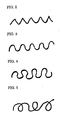
- short fibers or tow having crimp shown in FIG. 2, 3, 4 or 5 can be produced.
- fibers having zigzag crimps shown in FIG. 2 or U-shape crimps shown in FIG.3 are obtained.
- fibers having ⁇ -shape crimps shown in FIG. 4 or spiral crimps shown in FIG.3 are obtained.
- shape of crimps is varied depending on production factors such as nature of single thermoplastic resin or two thermoplastic resins being combined, condition of spinning, stretching, or condition of thermal treatment after crimping.
- the embodied example of this invention is equipped with a dryer 5 having heating means for drying or annealing the tow between the high-speed crimping processor 4 and a tow cutter 6.
- a dryer conveyer 36 drying and conveying the tow step by step is used as the heating means.
- thermoplastic synthetic fibers producing apparatus of this invention further is equipped with any of a tow cutter 6, a tow winder 7, and a tow box packing device 8.
- the apparatus is also equipped with post-drying guide roll(s) 38 for guiding the tow into each process after drying. With these means, it is possible to produce any of the short fibers and the tow (FIG. 1).
- the tow cutter can be any type as long as it can cut the tow at high speed.
- the tow winder 7 can be any type as long as it can wind the tow having large total fineness as preliminary discussed.
- the tow box packing device 8 can be equipped.
- thermoplastic synthetic fibers producing apparatus of this invention arranges the devices for sequential time-to-time processing steps functionally and compactly, such as the melt spinning device 1, the drawn tow accumulating device 2, and the high-speed stretching device 3.
- the high-speed stretching device 3 and the high-speed crimping processor 4 are arranged according to the right direction as shown in FIG. 1, however the arrangement direction of the post-spinning devices including the drawn tow accumulating device 2 is not limited as embodied herein.
- any or all of the high-speed stretching device 3, the high-speed crimping processor 4, the dryer 5, the tow cutter 6 and the tow winder 7 may be arranged on the upper level.
- the melt spinning device 1 of this embodied example exemplifies the spinning block 9 to which four spinneret blocks 40 can be attached per one spinning block, but it is possible to use a spinning block to which two to forty can be attached. And the spinning block 9 can be plural of spinning blocks which two to six spinneret blocks can be attached per one spinning block. Also it is possible to use a spinning block which spinneret blocks are attached from upside or horizontal side.
- thermoplastic synthetic fibers producing apparatus of this invention it is possible to produce regular fibers made of a single thermoplastic resin or a mixture of plural thermoplastic resins, and composite fibers.
- composite fibers it is possible to produce fibers having any composite configuration of a sheath-core configuration, an eccentric sheath-core configuration, a multiply splittable configuration, a hollow multiply splittable configuration, a non-circular configuration.
- a spinnable thermoplastic resin such as a polypropylene, a high density polyethylene, a low density polyethylene, a linear low density polyethylene, and a copolymer containing two to four components of propylene main component and other ⁇ -olefin(s), a polyamide resin such as a nylon-6, and a nylon-66, a polyester resin such as a polyethylene terephthalate, a copolymer of polyethylene terephthalate - isophtalate, and a polybutylene terephthalate can be exemplified. Also a polyphenylene sulfide, a polystyrene, a polyvinylidene fluoride can be exemplified.
- thermoplastic resins suitably selected from the above mentioned resins.
- a combination such as high density polyethylene /polypropylene, linear low density polyethylene /polypropylene, linear low density polyethylene /polyethylene terephthalate, propylene-ethylene copolymer /polypropylene, propylene-ethylene-butene-1 copolymer /polypropylene, high density polyethylene / polyethylene terephtalate.
- sheath-core composite fiber wherein the sheath component is the high density polyethylene and the core component is the polypropylene, referring to FIG. 1.
- the total fineness of the obtained fibers is 105,600 dtex as after stretched, and all the process steps from the composite fibers spinning, via the high-speed stretching and the high-speed crimping, to the short fiber cutting are continuously conducted, namely it is the in-line process.
- a high density polyethylene was melted and extruded from the extruder a 15 at a temperature of 240 °C, and a polypropylene was melted and extruded from the extruder b 16 at a temperature of 300 °C.
- Each melted resin was passed through each transfer block 17and 18, and sent into the gear pumps of each component 19 and 20, then sent into the spinneret blocks being measured with the gear pumps, and sheath-core composite fibers were spun from the spinneret blocks.
- the spun fibers were immediately cooled by the quenching devices 24, a finish oil was uniformly applied onto the fibers with the oiling devices 13, then the four pre-bundled fibers were drawn with the tow drawing rolls 11 and bundled together as a tow P.
- This tow was sent to the two guide rolls 26 equipped to the drawn tow accumulating device 2, and nipped between the tow feeding rolls 28, then fed and accumulated on the tow accumulating conveyer 29 being traversed in front and back sides direction by the tow feeding chute (not shown in FIG. 1) equipped under the tow feeding rolls, then conveyed and stocked in right direction of the conveyer.
- the tow accumulation quantity was detected by the tow accumulation state detecting sensor 31, and analyzed by a means for image analysis, then the sensor sent a command for controlling the stretching speed to the high-speed stretching device of the next process, and the tow accumulation quantity on the conveyer was kept to be constant.
- the sensor can also control the speed of the tow accumulating conveyer. But in this example, the command was sent to the speed of the high-speed stretching device.
- the tow P was sent to the guide rolls 30 having pinch roll formation, then sent to the high-speed stretching device 3, and stretched at 110 °C of stretching temperature, at 3.2 times of stretching ratio, and at 2,000 m / min. of stretching speed.
- the total fineness of the stretched tow Q was 105,600 dtex.
- the stretched tow was crimped with the high-speed crimping processor 4 to obtain a crimped tow R having 14 crimps / 25 mm.
- the crimped tow R was sent to the dryer 5 with the dryer conveyer 36, and dried at 110 °C, then sent to the tow cutter 6 passing through the post-drying guide roll 38 to obtain short fibers having 2.2 dtex of single fiber fineness and 51 mm of fiber length.
- thermoplastic synthetic fibers producing apparatus of this invention is equipped with the drawn tow accumulating device 2, so that the apparatus of this invention does not require widely extended area for stocking empty tow cans nor tow cans filled with unstretched tow of fibers. Also the apparatus of this invention does not require a long and large area occupying conveyer for conveying tow cans. Also for this invention, operations manually done by operators are not required, such as moving tow cans nor hooking fibers onto many guides. And many wastes of thread do not come out at the starting time or the stopping time of the stretching.
- compactly arranged is not only the drawn tow accumulating device, but also whole set including other devices such as the melt spinning device, the high-speed stretching device, and the high-speed crimping processor, so that the operability is good and the reduction of labor is possible. Furthermore, continuous high speed production is possible from the melt spinning process to the stretching process, further to the crimping process.
- the tow drawing and stretching device equipped to the apparatus of this invention it is possible to accumulate many amount of the tow on the conveyer, so that operations such as changing stretching condition and changing crimping condition are possibly done without stopping the producing line driving. Also this invention is applicable for temporally stopping each device arranged after the stretching process to be checked and maintained. And the tow once accumulated on the tow accumulating conveyer can be changed to be stretched being sent from the tow feeding rolls directly to the stretching device, so that a whole of the apparatus is compact and operability is good.
- the tow accumulation sensor and the means for image analysis are equipped, and the quantity of accumulated tow can be controlled under commanding information from them, it is possible to drive the apparatus continuously for long time. And the tow is stretched immediately after spinning, so that crystallization of the unstretched fibers due to long time storage does not occur. Accordingly, the fibers can be stretched uniformly without breakage.
- the high-speed crimping processor is equipped for handling large fineness fibers at high speed, it is possible to drive the apparatus of this invention for long time with high productivity. And the crimping processor of "Ring Roll” type further contributes to the long time driving, because its check and maintenance is easy.
- the synthetic, fibers producing apparatus of this invention further comprising the dryer, the tow cutter, the tow winder and the tow box packing device enables drying and annealing of the tow, and also enables producing any of the short fibers and the tow freely and continuously.
Landscapes
- Engineering & Computer Science (AREA)
- Mechanical Engineering (AREA)
- Textile Engineering (AREA)
- Spinning Methods And Devices For Manufacturing Artificial Fibers (AREA)
- Yarns And Mechanical Finishing Of Yarns Or Ropes (AREA)
Abstract
Description
- This invention relates to an apparatus and a method for producing thermoplastic synthetic fibers, especially fibers used for non-woven fabrics or other clothes. More specifically, it relates to a compact apparatus which can produce regular fibers, composite fibers and so on, continuously throughout from melt spinning step to final fiber obtaining step with high speed. Furthermore specifically, it relates to an apparatus equipped with a melt spinning device, a tow drawer and a tow accumulating device, a high-speed tow stretching device, and so on, being arranged functionally according to sequential time-to-time processing steps of materials, applicable for producing a tow having a large fineness such as 10,000 dtex or more, and a producing method using the said apparatus.
- Generally, as apparatus for producing thermo-plastic synthetic fibers, there have been two types of apparatus as roughly classified. The first is for producing continuous fibers (long fiber or filament) having a small amount of total fineness that are to be directly knitted (or woven) with a knitting machine or a weaving machine, then processed into clothes or the like. The second is for producing short fibers (staples) or a tow supplied as woven or non-woven fabrics produced through intermediate steps of spinning, carding, and so on.
- In the case of said first apparatus for producing continuous fiber, the total fineness of the obtained fibers is small as 50 - 3000 dtex at most. As the first apparatus for producing continuous fibers, a high-speed apparatus so called "Spin-Draw-Texture type" is conventionally known, which spins fibers from its each spinneret, stretches the fibers at high speed, processes the fibers to be bulky, then winds the fibers on its winder. This apparatus is applicable for small fineness fibers such as previously mentioned. Accordingly, it is possible to produce continuous fibers at a high speed of 3,000 - 7,000 m / min. approximately. However, in the case of producing short fibers or tow using the first apparatus, it is necessary to set many paper tubes (bobbins of wound fibers) to creels after crimping process, then unwind the fibers as tows and be re-processed. Thus it requires widely extended area for device of creels, and it is uneconomical from the view point of operability or re-processing.
- As the second type apparatus for producing short fibers or a tow, an apparatus so called "Short-Spin type" is conventionally known which arranges a melt spinning device equipped with a large-size spinneret which many spinning holes are bored, a low-speed stretching device, and a stuffer type crimping processor. In the case of this Short-Spin type apparatus, unstretched fibers are spun at low speed from a large-size spinneret which approximately 3,000 - 50,000 spinning holes are bored, then stretched at a low speed of 30 - 150 m / min. to give a tow having a total fineness of approximately 500,000 - 2,500,000 dtex. In this apparatus, the size of the spinneret is large, and the density of the bored spinning holes is high, so that the distribution of raw resin inside spinneret tends to be ununiform, also the fineness of spun fibers tends to be ununiform. Further in the case of producing composite fibers, causing the bad influence of said ununiformity of the distribution for two kinds of thermo-plastic resins, it is difficult to produce the fibers having uniformed composite ratio with less eccentricity. Also further the case of producing fibers having small fineness, that is 3 dtex or less of single fiber fineness, breakage of single fiber or melting adhesion of each single fibers tend to occur.
- Also in the case such as when spun fibers were wound on stretching device, or when fine adjustment of the crimping processor was required, it is necessary to stop the apparatus as a whole including spinning device, and many wastes of thread come out, so it has been problem on this apparatus.
- Also there has been another conventional possibility to produce the tow having large fineness arranging an apparatus so called "Conventional Type" equipped with many relatively small spinneret blocks and the density of the bored spinning holes is low. But for the reason of many spinnerets being required, the spinning block become long and large. Accordingly, it requires the great works for changing each spinneret or checking and maintenance of related equipment such as gear pumps for each spinneret, so that the operability of this apparatus would become bad.
- Further for this apparatus, it requires many cans for stocking unstretched tows, much enlarged area for operation is required.
- Japanese Patent Publication (Tokkyo Kokai Koho) Hei 7-216626 (coresponding to US 5411693) discloses a Short-Spin type apparatus for producing composite fibers comprising a spinning block equipped with a large-size spinneret wherein many spinning holes are bored, and a special quenching device blowing high-speed air into the space just under the surface of the spinneret from one side. In this apparatus, the production speed is low because it is not equipped with high-speed stretching device nor high-speed crimping processor. Further, properties of each single fiber tend to become ununiform, such as ununiformed fineness or ununiformed strength, causing localized cooling of spinneret surface from high-speed quenching air stream. Also the surface of spinneret is easily cooled, so that it is difficult to keep spinability and uniformed fiber properties for long time. Furthermore, this apparatus also contains the same peculiar problem for the Sort-Spin Type as previously mentioned.
- Japanese Patent Publication (Tokkyo Kokai Koho) Hei 3-130407 (corresponding to US 5079812) discloses an automatic tow exchanging apparatus for feeding a tow into a can, equipped with pairs of tow feeding rolls on frontside and backside of the apparstus. This apparatus can make rapid exchange of the tow possible, but it is a type of feeding the tow into a can, so that it is impossible to produce the tow continuously from the spinning step, via the stretching step to the crimping step.
- The object of the present invention is to provide a fiber production apparatus, which is capable to produce fibers having large total fineness of approximately 10,000 - 440,000 dtex continuously from the melt spinning step to the final (e.g. crimping) step at high stretching speed approximately 300 - 6,000 m / min., and which has compact whole size. A further object is to provide a fiber production apparatus wherein the spinning block is easily checked and maintained. A still further object is to provide such apparatus having a means for stocking the tow temporarily. Further, it aims to provide a fiber production apparatus which can pass the fibers into a stretching step directly from the spinning step when the apparatus is continuously driven. Furthermore, it aims to be applicable for producing various kinds of fibers such as regular fibers or composite fibers. It further aims to solve the above mentioned problem existing in the continuos long fiber producing apparatus such as Spin-Draw-Texture type, or the short fiber producing apparatus such as Short Spin type and Conventional type.
- To solve the above problem, this invention is constructed as the followings;
- 1. A compact in-line high-speed apparatus for producing
thermoplastic synthetic fibers comprising;
- a) a melt spinning device equipped with a spinning
block and a tow drawer
wherein the spinning block has at least one extruder, at least one spinneret block, and heating means, and the tow drawer draws fibers spun from the spinning block as a bundled tow, - b) a drawn tow accumulating device equipped with at least two tow feeding rolls and a tow accumulating conveyer wherein the tow feeding rolls can feed the tow obtained from the tow drawer onto the tow accumulating conveyer, and the tow accumulating conveyer can accumulate the tow fed from the tow feeding rolls, and
- c) a high-speed tow stretching device stretching the tow supplied from the drawn tow accumulating device at high stretching speed.
- 2. The compact in-line high-speed apparatus for producing thermoplastic synthetic fibers according to the above item 1, further comprising a high-speed crimping processor next to the high-speed stretching device for crimping the stretched tow at high speed.
- 3. The compact in-line high-speed apparatus for producing
thermoplastic synthetic fibers according to the
above items 1 or 2, further comprising a tow cutter for cutting the stretched tow into short fibers as final products. - 4. The compact in-line high-speed apparatus for producing thermoplastic synthetic fibers according to any one of the items 1 to 3, further comprising a tow winder or a tow box packing device for preparing the stretched tow as a final product.
- 5. The compact in-line high-speed apparatus for producing thermoplastic synthetic fibers according to any one of the items 1 to 4, wherein the drawn tow accumulating device is further equipped with a sensor detecting the accumulation state of the tow.
- 6. The compact in-line high speed apparatus for producing thermoplastic synthetic fibers according to any one of the items 1 to 5, wherein at least one of the tow feeding rolls is a pinch roll and at least one of the tow feeding rolls has a mechanism to take off from the tow passing route.
- 7. The compact in-line high speed apparatus for producing thermoplastic synthetic fibers according to any one of the items 1 to 6, wherein the melt spinning device is equipped with at least two extruders for producing multi-component thermoplastic synthetic conjugated fibers comprising at least two components.
- 8. The compact in-line high speed apparatus for producing thermoplastic synthetic fibers according to any one of the items 1 to 7, wherein the high-speed tow stretching device is equipped with a mechanism which can stretch a tow having a total fineness of 10,000 - 440,000 dtex at a spinning speed of 300 - 6,000 m/min.
- 9. The compact in-line high speed apparatus for producing thermoplastic synthetic fibers according to any one of the items 1 to 8, wherein the spinneret blocks are for spinning composite fibers having sheath-core or side-by-side configuration.
- 10. A method for producing thermoplastic synthetic fibers using the compact in-line high-speed apparatus for producing thermoplastic synthetic fibers as defined in any one of the items 1 to 9, characterized in supplying a tow fed from tow feeding rolls directly to a tow stretching device, or taking at least one of the tow feeding rolls off from the tow passing route, in the high speed stretching step.
-
- The "Compact in-line high speed apparatus for producing thermoplastic synthetic fibers" defined in this invention means an apparatus for thermoplastic synthetic fiber production which is equipped with devices for each process of melt spinning, tow drawing and accumulation, high-speed stretching, and optionally high-speed crimping, tow cutting and/or tow winding, along time-to-time sequence into one continuous line, processing raw material resins into final product of fibers (tow), at high speed.
-
- FIG. 1 shows a whole outlined front view of the apparatus of this invention.
- FIG. 2 shows a fiber having zigzag-shaped crimps.
- FIG. 3 shows a fiber having U-shaped crimps.
- FIG. 4 shows a fiber having Ω-shaped crimps.
- FIG. 5 shows a fiber having spiral crimps.
-
- In FIG. 1, each symbol has the following meaning: 1: Melt spinning device, 2: Drawn tow accumulating device, 3: High-speed stretching device, 4: High speed crimping processor, 5: Dryer, 6: Tow cutter, 7: Tow winder,8: Tow box packing device, 9: Spinning block, 10: Tow drawer, 11: Tow drawing rolls. 12: Tow drawer panel, 13: Oiling devices, 14: Hopper, 15: Extruder a, 16: Extruder b, 17: Transfer block a, 18: Transfer block b, 19: Gear pump a, 20: Gear pump b, 21: Gear pump driving motor a, 22: Gear pump driving motor b, 23: Assistant roll, 24: Quenching devices, 25: Spun fibers, 26: Guide roll of drawn tow accumulating device, 27: Drawn tow accumulating device panel, 28: Tow feeding rolls, 29: Tow accumulating conveyer, 30: Guide pinch rolls, 31: Tow accumulation sensor, 32: First set of stretching rolls, 33: Second set of stretching rolls, 34: Nipping roll type crimper, 35: Compressing chamber, 36: Dryer conveyer, 37: Stretching rolls, 38: Post-drying guide rolls, 39: Guide pinch rolls for packing tow, 40: Spinneret blocks, P: Unstretched tow, Q: Stretched tow, R: Crimped tow, S: Short fibers, Y: Direct tow passing route.
- This invention is explained based on an embodied example of an apparatus for producing bi-component composite fibers hereinafter. FIG. 1 shows an outlined front view of this embodied apparatus as a whole, for explaining this invention. In FIG. 1, the apparatus of this invention comprises three devices as roughly separated, which are the melt spinning device 1, the drawn
tow accumulating device 2, and the high-speed stretching device 3. These devices are arranged compactly according to the sequential processing order. In this embodied example, it is possible to produce both kinds of short fibers (staples) and a tow (bundled long filaments), and also possible to produce both of crimped and non-crimped fibers. Accordingly, this embodied apparatus is also equipped with optional devices such as the high-speed crimping processor 4, the tow cutter 6, the tow winder 7, the towbox packing device 8, and thetow dryer 5. The main component of the melt spinning device is installed at upper level, and enables the spinning block 9 to spin fibers as four pre-bundled fibers per one spinning block at the same time. And thequenching devices 24 are installed just under the spinning block for cooling the spun fibers. Also thetow drawer 10 is installed further under the spinning block 9 for drawing and bundling the fibers spun from the spinning device 1 as a tow. - In FIG. 1, two
extruders extruders - The spinning block 9 has four opening cavities in the same line for attaching spinneret blocks 40. In this embodied apparatus, the spinneret blocks 40 are attached with fastening bolts from downside. This spinning block forms a closed box, and has a heating means. The heating means can be any type such as a device heated with a liquid heating medium such as Dowtherm, a device circulating a heating medium of liquid or gas heated at outside, or a built-in metallic cast heater.
- Concerning the plane shape of the spinning block 9 of this invention, it is sufficient that the shape of its cavity for attaching the spinneret matches the shape of the spinneret block, like the plane shape of circle, quadrangle, rectangle or oval can be used.
- In this embodied example, used spinneret block 40 is for producing bi-component composite fibers, this block consists of main component members such as a cap functioned as an entrance of melted raw resin, a first distributing plate, a second distributing plate, a spinneret plate and flanges. The spinneret plate is set between flanges and fixed with bolts.
- The apparatus of this embodied example comprises quenching devices under the spinneret blocks, wherein the number of the quenching devices is same as the number of the spinneret blocks, namely as the number of pre-bundled fibers. The type of quenching devices used in this embodied example blows cooling air from one side. In this invention, the quenching device(s) can be any of out-in type and in-out type to blow cooling gas (air). Further, the apparatus of this invention can be equipped with quenching gas flow stabilizing ducts under the quenching devices. Furthermore, this invention may be equipped with no quenching device.
- The melt spinning device of this embodied example comprises a
tow drawer 10 equipped with oilingdevices 13 applying finish oil onto each pre-bundled fiber and tow drawing rolls 11 on a tow drawer panel 12 under the spinning block (FIG. 1). In the apparatus of this invention, the oiling device(s) can be any type as long as the finish oil can be applied onto thefibers 25. For example, an oiling device such as a box type flowing finish oil from its slit, or a spray type can be exemplified. Addition to thetow drawer 10, anassistant roll 23 is equipped to be used for starting time of the spinning or for fiber breakage. As to the number of said assistant roll(s), it is sufficient that one assistant roll per 1 - 6 pre-bundled fiber(s) is equipped. - The above oiling rolls, drawing rolls and assistant roll are connected to driving means.
- The synthetic fibers producing apparatus of this embodied example comprises a
tow accumulating device 2 equipped with tow feeding rolls 28, and atow accumulating conveyer 29 accumulating the fed tow, before the stretching step, as shown in FIG. 1, at the left side of the tow stretching device 3. The end-part of thetow accumulating conveyer 29 is located under the tow feeding rolls 28 (FIG. 1). And the tow feeding rolls 28 consist of a pair of pinch rolls of left and right sides, each roll is equipped with driving motor (not shown in FIG. 1), and installed in a drawn tow accumulatingdevice panel 27. Also thetow accumulating device 2 is equipped with 2 tow guide rolls 26 driven by motors (these motors are not shown in FIG. 1 too) at the entrance side of the tow. - This invention may further comprise a feeding chute equipped with a traversing device under the tow feeding rolls 28. In the case of equipping the traversing device, the tow is traversed between front and back sides on FIG. 1, and accumulated on the conveyer across the direction crossing the conveyer movement, and large amount of tow can be accumulated. This conveyer is driven by a conveyer driving motor, and conveys a tow from the right to the left direction on FIG. 1. The accumulating
device 2 functionally works for supplying the tow continuously to the next processing step of the stretching. Additionally, thetow accumulating conveyer 29 can work functionally to stock the tow temporarily for tow hooking operation of starting time at low speed onto the high-speed stretching device of the next step. Also this temporal tow stocking function can be applicable for some occasional trouble in the following steps such as in the high-speed stretching device, the high-speed crimping processor, or the cutter, or for the case such as fiber stretching condition adjustment is required, without stopping the spinning operation. - The number of guide roll(s) 26 can be one to seven, generally tow to five is suitable. These guide rolls work functionally to make fluttering tension of unstretched tow (P) supplied from the
tow drawer 10 being constant, or to avoid the tow being wound on the tow feeding rolls. Also the guide rolls enable easy starting operation of tow feeding. - As the tow feeding rolls 28, a pair of flat rolls, a pair of grooved rolls of gear type, a combination of metal flat roll and rubber roll can be used. Among these, especially the pair of grooved metal rolls of gear type is preferably used, because the tow does not slip between nipping rolls and is not wound on the rolls, so that stable production of the tow can be continued for long time.
- In the synthetic fibers producing apparatus of this invention, the tow feeding rolls 28 may have the mechanism which enabling at least one of the tow feeding rolls taken off from the tow passing route (any of the left and the right roll, or both of them). This mechanism may be a means removing one of, or both of the pair tow feeding rolls into the direction of upside, downside, backside or frontside, to take the roll(s) off from the tow passing route. Applying this mechanism enables high-speed stretching of the tow directly supplied from the spinning step with the stretching device 3, without being accumulated on the
conveyer 29. - According to this invention, it is possible to accumulate the tow on the
conveyer 29 temporarily, stretching the tow with the high-speed stretching device 3, then increasing stretching speed step by step, afterward the tow is passing between the pair of tow feeding rolls, and processed directly connected to the high-speed stretching device 3, without being accumulated on theconveyer 29, as the broken line of the tow passing rout Y shown in the FIG. 1. Thus the tow having the total fineness of 10,000 dtex or more can be stretched at the high speed of 1,000 m / min. or more. - The
tow accumulating conveyer 29 can be made of any material such as a metal net, a synthetic resin net, a woven net combining metal and synthetic resin, an elastic material belt such as a rubber, and a cloth belt. - In this embodied example, a tow accumulation
state detecting sensor 31 is installed above the tow accumulating conveyer. This sensor detects and analyzes the tow accumulation state with pre-installed means for image analysis, to control the tow accumulation state, increasing or decreasing the speed of the tow accumulating conveyer, or the speed of the stretching device. In this apparatus, the speed of the conveyer or the stretching device is controlled with both of a command from the sensor and the manual operation. - The thermoplastic synthetic fibers producing apparatus of this invention comprises the high-speed stretching device ahead to the high-speed crimping processor (FIG. 1). In this invention, it is sufficient that the apparatus comprises a mechanism enabling to stretch the tow having approximately 10,000 - 440,000 dtex of total fineness as after stretched at approximately 300 - 6,000 m / min. of stretching speed, for example a great horsepower driving motor. Namely, it is a device for high-speed stretching large fineness tow. Especially, it is preferable to use a device enabling the stretching tow having approximately 10,000 - 400,000 dtex of total fineness as after stretched at approximately 1,000 - 5,000 m / min. of stretching speed. In this embodied example, used is a compact stretching device combining the first set and the second set of stretching rolls, wherein each set of stretching rolls comprises three stretching
rolls 37 having heating means. - The heating means of stretching rolls is not limited as long as it enables heating at approximately 50 - 200 C°. The heating means can be any of a dielectric heating type, a built-in cast heater type and a liquid heating medium type. Also the state of the stretching rolls arrangement and the number of the stretching rolls are not limited. Further, a high-sped stretching device of Nelson's roll type can be used. And the stretching device 3 can change its driving speed both into approximately 5 - 100 m / min. of low-speed driving at stretching start time and approximately 300 - 6,000 m / min. of high-speed driving in running actual production.
- In this embodied example, guide rolls 30 of pinch roll type are installed on the entrance side of the first set of stretching rolls for guiding the tow properly into the stretching rolls. These guide rolls can be replaced by one grooved free roll. Also other kind of guiding device can be used instead of these rolls.
- Furthermore, as the high-speed stretching device of the synthetic fibers producing apparatus of this invention, a box type stretching device having built-in stretching rolls or a chamber type stretching device equipped with one roll per one chamber can be used. Also a multi-step stretching device equipped with multiple stretching blocks having 4 - 10 stretching rolls per one stretching block can be used.
- The high-speed stretching device 3 of this embodied example can control the amount of accumulated tow on the
conveyer 29 being constant, controlling stretching speed automatically based on the command from thetow accumulation sensor 31. Obviously, this stretching condition can be also controlled by manual operation. Also it is possible to stretch the tow fed directly from the tow feeding rolls 28 without accumulating the tow on theconveyer 29. - In the thermoplastic synthetic fibers producing apparatus of this invention, the high-speed crimping processor is arranged after the tow stretching device (FIG. 1). This high-speed crimping processor can be any type of device as long as it can crimp the large fineness tow at high speed. In this embodied example, a nipping
roll type crimper 34 having a compressingchamber 35 is installed. - In this invention, a crimping processor so-called "Inscription in Ring Roll Type" described in the Japanese Tokkyo Kokai Koho "Hei4-308236" can be used, which comprises rotating large diameter ring roll and rotating small diameter inner roll inscribed in the large ring roll arranged to have small nipping clearance.
- Further as the crimping processor, an air forcing type crimping processor can be used. The crimping processor of this type is forcing the tow into the processor with high pressure air to make the tow crimped. The forcing air can be used as heated. Usually the air is used as heated at 80 - 200 °C with 0.15- 1 MPa of pressure.
- With the above crimping processor, short fibers or tow having crimp shown in FIG. 2, 3, 4 or 5 can be produced. In the case of processing regular fibers of non-composite type or sheath-core composite fibers of non-eccentric type, fibers having zigzag crimps shown in FIG. 2 or U-shape crimps shown in FIG.3 are obtained. In the case of processing side-by-side composite fibers or eccentric sheath-core composite fibers, fibers having Ω-shape crimps shown in FIG. 4 or spiral crimps shown in FIG.3 are obtained. Of course, it is obvious that the shape of crimps is varied depending on production factors such as nature of single thermoplastic resin or two thermoplastic resins being combined, condition of spinning, stretching, or condition of thermal treatment after crimping.
- According to this invention, it is also possible to produce substantially non-crimped fibers without using the high-speed crimping processor.
- The embodied example of this invention is equipped with a
dryer 5 having heating means for drying or annealing the tow between the high-speed crimping processor 4 and a tow cutter 6. In this case, adryer conveyer 36 drying and conveying the tow step by step is used as the heating means. - The thermoplastic synthetic fibers producing apparatus of this invention further is equipped with any of a tow cutter 6, a tow winder 7, and a tow
box packing device 8. The apparatus is also equipped with post-drying guide roll(s) 38 for guiding the tow into each process after drying. With these means, it is possible to produce any of the short fibers and the tow (FIG. 1). - The tow cutter can be any type as long as it can cut the tow at high speed. For example, it is possible to use any of type of cutter forcing a tow between an lower rotary having many blades and a upper rotary and cutting the tow by rotating the both rotaries (FIG. 1), and forcing a tow between an rotary having many blades and a pushing roll and cutting the tow by rotating the rotary.
- The tow winder 7 can be any type as long as it can wind the tow having large total fineness as preliminary discussed. Instead of the tow winder, the tow
box packing device 8 can be equipped. - The thermoplastic synthetic fibers producing apparatus of this invention arranges the devices for sequential time-to-time processing steps functionally and compactly, such as the melt spinning device 1, the drawn
tow accumulating device 2, and the high-speed stretching device 3. In the embodied example of this invention, the high-speed stretching device 3 and the high-speed crimping processor 4 are arranged according to the right direction as shown in FIG. 1, however the arrangement direction of the post-spinning devices including the drawntow accumulating device 2 is not limited as embodied herein. - Furthermore, any or all of the high-speed stretching device 3, the high-speed crimping processor 4, the
dryer 5, the tow cutter 6 and the tow winder 7 may be arranged on the upper level. - The melt spinning device 1 of this embodied example exemplifies the spinning block 9 to which four spinneret blocks 40 can be attached per one spinning block, but it is possible to use a spinning block to which two to forty can be attached. And the spinning block 9 can be plural of spinning blocks which two to six spinneret blocks can be attached per one spinning block. Also it is possible to use a spinning block which spinneret blocks are attached from upside or horizontal side.
- Using the thermoplastic synthetic fibers producing apparatus of this invention, it is possible to produce regular fibers made of a single thermoplastic resin or a mixture of plural thermoplastic resins, and composite fibers. In the case of producing composite fibers, it is possible to produce fibers having any composite configuration of a sheath-core configuration, an eccentric sheath-core configuration, a multiply splittable configuration, a hollow multiply splittable configuration, a non-circular configuration. As a spinnable thermoplastic resin, a polyolefin resin such as a polypropylene, a high density polyethylene, a low density polyethylene, a linear low density polyethylene, and a copolymer containing two to four components of propylene main component and other α-olefin(s), a polyamide resin such as a nylon-6, and a nylon-66, a polyester resin such as a polyethylene terephthalate, a copolymer of polyethylene terephthalate - isophtalate, and a polybutylene terephthalate can be exemplified. Also a polyphenylene sulfide, a polystyrene, a polyvinylidene fluoride can be exemplified.
- In the case of composite fibers, it is possible to combine the thermoplastic resins suitably selected from the above mentioned resins. For example, possibly exemplified is a combination such as high density polyethylene /polypropylene, linear low density polyethylene /polypropylene, linear low density polyethylene /polyethylene terephthalate, propylene-ethylene copolymer /polypropylene, propylene-ethylene-butene-1 copolymer /polypropylene, high density polyethylene / polyethylene terephtalate.
- Explained herein is a production example of a sheath-core composite fiber wherein the sheath component is the high density polyethylene and the core component is the polypropylene, referring to FIG. 1. Addition to this example, the total fineness of the obtained fibers is 105,600 dtex as after stretched, and all the process steps from the composite fibers spinning, via the high-speed stretching and the high-speed crimping, to the short fiber cutting are continuously conducted, namely it is the in-line process.
- Four sheath-core spinneret blocks were attached to the spinning block 9. This spinning block was heated at 280 °C.
- A high density polyethylene was melted and extruded from the extruder a 15 at a temperature of 240 °C, and a polypropylene was melted and extruded from the
extruder b 16 at a temperature of 300 °C. Each melted resin was passed through eachtransfer block 17and 18, and sent into the gear pumps of eachcomponent 19 and 20, then sent into the spinneret blocks being measured with the gear pumps, and sheath-core composite fibers were spun from the spinneret blocks. The spun fibers were immediately cooled by thequenching devices 24, a finish oil was uniformly applied onto the fibers with theoiling devices 13, then the four pre-bundled fibers were drawn with the tow drawing rolls 11 and bundled together as a tow P. This tow was sent to the two guide rolls 26 equipped to the drawntow accumulating device 2, and nipped between the tow feeding rolls 28, then fed and accumulated on thetow accumulating conveyer 29 being traversed in front and back sides direction by the tow feeding chute (not shown in FIG. 1) equipped under the tow feeding rolls, then conveyed and stocked in right direction of the conveyer. The tow accumulation quantity was detected by the tow accumulationstate detecting sensor 31, and analyzed by a means for image analysis, then the sensor sent a command for controlling the stretching speed to the high-speed stretching device of the next process, and the tow accumulation quantity on the conveyer was kept to be constant. In addition to this example, the sensor can also control the speed of the tow accumulating conveyer. But in this example, the command was sent to the speed of the high-speed stretching device. - The tow P was sent to the guide rolls 30 having pinch roll formation, then sent to the high-speed stretching device 3, and stretched at 110 °C of stretching temperature, at 3.2 times of stretching ratio, and at 2,000 m / min. of stretching speed. The total fineness of the stretched tow Q was 105,600 dtex.
- The stretched tow was crimped with the high-speed crimping processor 4 to obtain a crimped tow R having 14 crimps / 25 mm. The crimped tow R was sent to the
dryer 5 with thedryer conveyer 36, and dried at 110 °C, then sent to the tow cutter 6 passing through the post-drying guide roll 38 to obtain short fibers having 2.2 dtex of single fiber fineness and 51 mm of fiber length. - These composite fibers had been produced continuously for six days, stable production had been possible. Effect of the invention
- The thermoplastic synthetic fibers producing apparatus of this invention is equipped with the drawn
tow accumulating device 2, so that the apparatus of this invention does not require widely extended area for stocking empty tow cans nor tow cans filled with unstretched tow of fibers. Also the apparatus of this invention does not require a long and large area occupying conveyer for conveying tow cans. Also for this invention, operations manually done by operators are not required, such as moving tow cans nor hooking fibers onto many guides. And many wastes of thread do not come out at the starting time or the stopping time of the stretching. Further in the apparatus of this invention, compactly arranged is not only the drawn tow accumulating device, but also whole set including other devices such as the melt spinning device, the high-speed stretching device, and the high-speed crimping processor, so that the operability is good and the reduction of labor is possible. Furthermore, continuous high speed production is possible from the melt spinning process to the stretching process, further to the crimping process. - Using the tow drawing and stretching device equipped to the apparatus of this invention, it is possible to accumulate many amount of the tow on the conveyer, so that operations such as changing stretching condition and changing crimping condition are possibly done without stopping the producing line driving. Also this invention is applicable for temporally stopping each device arranged after the stretching process to be checked and maintained. And the tow once accumulated on the tow accumulating conveyer can be changed to be stretched being sent from the tow feeding rolls directly to the stretching device, so that a whole of the apparatus is compact and operability is good.
- As the tow accumulation sensor and the means for image analysis are equipped, and the quantity of accumulated tow can be controlled under commanding information from them, it is possible to drive the apparatus continuously for long time. And the tow is stretched immediately after spinning, so that crystallization of the unstretched fibers due to long time storage does not occur. Accordingly, the fibers can be stretched uniformly without breakage.
- As the high-speed crimping processor is equipped for handling large fineness fibers at high speed, it is possible to drive the apparatus of this invention for long time with high productivity. And the crimping processor of "Ring Roll" type further contributes to the long time driving, because its check and maintenance is easy.
- The synthetic, fibers producing apparatus of this invention further comprising the dryer, the tow cutter, the tow winder and the tow box packing device enables drying and annealing of the tow, and also enables producing any of the short fibers and the tow freely and continuously.
Claims (10)
- A compact in-line high-speed apparatus for producing thermoplastic synthetic fibers comprising;a) a melt spinning device equipped with a spinning block and a tow drawer
wherein the spinning block has at least one extruder, at least one spinneret block, and heating means, and the tow drawer draws fibers spun from the spinning block as a bundled tow,b) a drawn tow accumulating device equipped with at least two tow feeding rolls and a tow accumulating conveyer wherein the tow feeding rolls can feed the tow obtained from the tow drawer onto the tow accumulating conveyer, and the tow accumulating conveyer can accumulate the tow fed from the tow feeding rolls, andc) a high-speed tow stretching device stretching the tow supplied from the drawn tow accumulating device at high stretching speed. - The compact in-line high-speed apparatus for producing thermoplastic synthetic fibers according to Claim 1, further comprising a high-speed crimping processor next to the high-speed stretching device for crimping the stretched tow at high speed.
- The compact in-line high-speed apparatus for producing thermoplastic synthetic fibers according to Claim 1 or 2, further comprising a tow cutter for cutting the stretched tow into short fibers as final products.
- The compact in-line high-speed apparatus for producing thermoplastic synthetic fibers according to any one of the Claims 1 to 3, further comprising a tow winder or a tow box packing device for preparing the stretched tow as a final product.
- The compact in-line high-speed apparatus for producing thermoplastic synthetic fibers according to any one of the Claims 1 to 4, wherein the drawn tow accumulating device is further equipped with a sensor detecting the accumulation state of the tow.
- The compact in-line high speed apparatus for producing thermoplastic synthetic fibers according to any one of the Claims 1 to 5, wherein at least one of the tow feeding rolls is a pinch roll and at least one of the tow feeding rolls has a mechanism to take off from the tow passing route.
- The compact in-line high speed apparatus for producing thermoplastic synthetic fibers according to any one of the Claims 1 to 6, wherein the melt spinning device is equipped with at least two extruders for producing multi-component thermoplastic synthetic conjugated fibers comprising at least two components.
- The compact in-line high speed apparatus for producing thermoplastic synthetic fibers according to any one of the Claims 1 to 7, wherein the high-speed tow stretching device is equipped with a mechanism which can stretch a tow having a total fineness of 10,000 - 440,000 dtex at a spinning speed of 300 - 6,000 m/min.
- The compact in-line high speed apparatus for producing thermoplastic synthetic fibers according to any one of the Claims 1 to 8, wherein the spinneret blocks are for spinning composite fibers having sheath-core or side-by-side configuration.
- A method for producing thermoplastic synthetic fibers using the compact in-line high-speed apparatus for producing thermoplastic synthetic fibers as defined in any one of the Claims 1 to 9, characterized in supplying a tow fed from tow feeding rolls directly to a tow stretching device, or taking at least one of the tow feeding rolls off from the tow passing route, in the high speed stretching step.
Applications Claiming Priority (2)
| Application Number | Priority Date | Filing Date | Title |
|---|---|---|---|
| JP1484299 | 1999-01-22 | ||
| JP01484299A JP4341095B2 (en) | 1999-01-22 | 1999-01-22 | High speed production apparatus and method for thermoplastic synthetic fiber |
Publications (2)
| Publication Number | Publication Date |
|---|---|
| EP1022364A1 true EP1022364A1 (en) | 2000-07-26 |
| EP1022364B1 EP1022364B1 (en) | 2009-03-25 |
Family
ID=11872303
Family Applications (1)
| Application Number | Title | Priority Date | Filing Date |
|---|---|---|---|
| EP00101205A Expired - Lifetime EP1022364B1 (en) | 1999-01-22 | 2000-01-21 | A high-speed apparatus and method for producing thermoplastic synthetic fibers |
Country Status (4)
| Country | Link |
|---|---|
| US (1) | US6383432B1 (en) |
| EP (1) | EP1022364B1 (en) |
| JP (1) | JP4341095B2 (en) |
| DE (1) | DE60041842D1 (en) |
Cited By (6)
| Publication number | Priority date | Publication date | Assignee | Title |
|---|---|---|---|---|
| EP1300496A1 (en) * | 2001-09-11 | 2003-04-09 | Neumag GmbH & Co. KG | Spin-drawing texturing apparatus |
| WO2006018240A1 (en) * | 2004-08-14 | 2006-02-23 | Saurer Gmbh & Co. Kg | Device and method for melt-spinning, drawing off, processing, and winding up several synthetic threads |
| WO2006061236A1 (en) * | 2004-12-10 | 2006-06-15 | Saurer Gmbh & Co. Kg | Device for producing, treating and further processing synthetic fibres |
| EP2161361A4 (en) * | 2007-06-22 | 2011-04-27 | Uni Charm Corp | Nonwoven fabric and process for producing the same |
| CN108842204A (en) * | 2018-09-07 | 2018-11-20 | 福建景丰科技有限公司 | A kind of achievable polyamide fibre fiber number adjustable spinning system on a large scale |
| US20240263356A1 (en) * | 2021-09-17 | 2024-08-08 | Beijing Chonglee Machinery Engineering Co., Ltd. | Spinning-Drawing-winding device and combined machine for industrial bio-based polyamide |
Families Citing this family (21)
| Publication number | Priority date | Publication date | Assignee | Title |
|---|---|---|---|---|
| US8363744B2 (en) * | 2001-06-10 | 2013-01-29 | Aloft Media, Llc | Method and system for robust, secure, and high-efficiency voice and packet transmission over ad-hoc, mesh, and MIMO communication networks |
| EP1390192A4 (en) * | 2001-04-20 | 2005-07-13 | Polymer Group Inc | PROCESS FOR PRODUCING NON-WOVEN FABRIC THAT CAN BE DRAPED AND FLEXIBLE |
| JP4149716B2 (en) * | 2002-03-01 | 2008-09-17 | 株式会社フジクラ | Optical fiber cord manufacturing method and apparatus |
| ITMI20041137A1 (en) * | 2004-06-04 | 2004-09-04 | Fare Spa | APPARATUS FOR THE TREATMENT OF SYNTHETIC YARNS |
| US7445737B2 (en) * | 2004-06-25 | 2008-11-04 | Celanese Acetate, Llc | Cellulose acetate tow and method of making same |
| JP4745789B2 (en) * | 2004-12-27 | 2011-08-10 | 三ツ星ベルト株式会社 | V-ribbed belt and method for manufacturing V-ribbed belt |
| CN101142347B (en) * | 2005-03-18 | 2010-05-19 | 戴奥伦工业纤维有限公司 | Manufacturing method of polyphenylene sulfide monofilament yarn |
| JP5251490B2 (en) * | 2008-01-09 | 2013-07-31 | 東レ株式会社 | Polyphenylene sulfide fiber and method for producing the same |
| US9181637B2 (en) * | 2009-12-09 | 2015-11-10 | Toray Industries, Inc. | Method for producing long fiber nonwoven fabric |
| CN104195659A (en) * | 2014-08-26 | 2014-12-10 | 江苏巨鸿超细纤维制造有限公司 | Polyester and chinlon composite yarn bundling device |
| US10634736B2 (en) * | 2017-06-12 | 2020-04-28 | Littelfuse, Inc. | Magnetoresistive sensors and switches from pre-bundled nanowires |
| JP7051323B2 (en) * | 2017-08-02 | 2022-04-11 | 帝人フロンティア株式会社 | Manufacturing method of non-crimped short fibers |
| CN108642583B (en) * | 2018-05-23 | 2021-04-20 | 北京中丽制机工程技术有限公司 | Spinning and drafting combination machine and single suction device for spinning machine |
| CN108642585B (en) * | 2018-05-23 | 2021-03-02 | 北京中丽制机工程技术有限公司 | FDY filament spinning and drawing combination machine |
| EP3666939B1 (en) | 2018-12-12 | 2024-10-30 | Aladdin Manufacturing Corporation | A multifilament bundle of melt spun polymer filaments |
| CN111424325B (en) * | 2020-01-20 | 2024-11-22 | 浙江新维狮合纤股份有限公司 | Post-spinning drafting and washing process and equipment |
| EP4164974A4 (en) | 2020-06-16 | 2025-01-08 | Aladdin Manufacturing Corporation | SYSTEMS AND METHODS FOR PRODUCING A FILAMENT BUNDLE AND/OR A YARN BUNDLE |
| US12071713B2 (en) * | 2020-06-16 | 2024-08-27 | Aladdin Manufacturing Corporation | Systems and methods for producing a bundle of filaments and/or a yarn |
| EP4600413A3 (en) | 2020-06-16 | 2025-10-08 | Aladdin Manufacturing Corporation | Systems and methods to provide color enhanced yarns |
| US12553154B2 (en) | 2021-04-23 | 2026-02-17 | Aladdin Manufacturing Corporation | Method of manufacturing yarn and yarn obtained in that manner |
| WO2023051721A1 (en) * | 2021-09-30 | 2023-04-06 | 北京中丽制机工程技术有限公司 | Fiber-spinning drafting and winding apparatus and combined machine for polylactic acid industry |
Citations (4)
| Publication number | Priority date | Publication date | Assignee | Title |
|---|---|---|---|---|
| US3958734A (en) * | 1974-10-24 | 1976-05-25 | Akzona Incorporated | Apparatus and method for controlling the inventory of the yarn mass within a confined space |
| JPS5215619A (en) * | 1975-07-25 | 1977-02-05 | Teijin Ltd | Process for spinning and drawing |
| US4105740A (en) * | 1973-12-26 | 1978-08-08 | Toyo Boseki Kabushiki Kaisha | Process for the production of polyester fiber |
| US4185064A (en) * | 1976-11-22 | 1980-01-22 | Barmag Barmer Maschinenfabrik Ag | Process for high speed production of filament cables |
Family Cites Families (9)
| Publication number | Priority date | Publication date | Assignee | Title |
|---|---|---|---|---|
| US3099064A (en) * | 1961-04-13 | 1963-07-30 | Eastman Kodak Co | Method and apparatus for making rug yarn |
| US3188713A (en) * | 1963-05-06 | 1965-06-15 | Eastman Kodak Co | Apparatus for processing crosssection yarn |
| US3380131A (en) * | 1964-07-13 | 1968-04-30 | Fiber Industries Inc | Method and apparatus deflecting and drawing tow |
| US4247270A (en) * | 1979-01-29 | 1981-01-27 | Iwka-Industrie-Werke-Karlsruhe Augsburg Ag | Apparatus for the continued manufacture of staple fibers from thermoplastic materials |
| US4284395A (en) * | 1979-12-12 | 1981-08-18 | Owens-Corning Fiberglas Corporation | Apparatus for forming filaments |
| US5079812A (en) | 1989-10-12 | 1992-01-14 | Chisso Corporation | Tow feeding apparatus |
| JP3134103B2 (en) | 1991-03-30 | 2001-02-13 | 株式会社竹原機械研究所 | Fiber crimping device |
| US5411693A (en) | 1994-01-05 | 1995-05-02 | Hercules Incorporated | High speed spinning of multi-component fibers with high hole surface density spinnerettes and high velocity quench |
| US5665300A (en) * | 1996-03-27 | 1997-09-09 | Reemay Inc. | Production of spun-bonded web |
-
1999
- 1999-01-22 JP JP01484299A patent/JP4341095B2/en not_active Expired - Fee Related
-
2000
- 2000-01-21 US US09/488,782 patent/US6383432B1/en not_active Expired - Lifetime
- 2000-01-21 EP EP00101205A patent/EP1022364B1/en not_active Expired - Lifetime
- 2000-01-21 DE DE60041842T patent/DE60041842D1/en not_active Expired - Lifetime
Patent Citations (4)
| Publication number | Priority date | Publication date | Assignee | Title |
|---|---|---|---|---|
| US4105740A (en) * | 1973-12-26 | 1978-08-08 | Toyo Boseki Kabushiki Kaisha | Process for the production of polyester fiber |
| US3958734A (en) * | 1974-10-24 | 1976-05-25 | Akzona Incorporated | Apparatus and method for controlling the inventory of the yarn mass within a confined space |
| JPS5215619A (en) * | 1975-07-25 | 1977-02-05 | Teijin Ltd | Process for spinning and drawing |
| US4185064A (en) * | 1976-11-22 | 1980-01-22 | Barmag Barmer Maschinenfabrik Ag | Process for high speed production of filament cables |
Non-Patent Citations (1)
| Title |
|---|
| PATENT ABSTRACTS OF JAPAN vol. 001, no. 054 (C - 014) 25 May 1977 (1977-05-25) * |
Cited By (8)
| Publication number | Priority date | Publication date | Assignee | Title |
|---|---|---|---|---|
| EP1300496A1 (en) * | 2001-09-11 | 2003-04-09 | Neumag GmbH & Co. KG | Spin-drawing texturing apparatus |
| US6890166B2 (en) | 2001-09-11 | 2005-05-10 | Neumag Gmbh & Co. Kg | Spinning-drawing-texturing machine |
| WO2006018240A1 (en) * | 2004-08-14 | 2006-02-23 | Saurer Gmbh & Co. Kg | Device and method for melt-spinning, drawing off, processing, and winding up several synthetic threads |
| WO2006061236A1 (en) * | 2004-12-10 | 2006-06-15 | Saurer Gmbh & Co. Kg | Device for producing, treating and further processing synthetic fibres |
| EP2161361A4 (en) * | 2007-06-22 | 2011-04-27 | Uni Charm Corp | Nonwoven fabric and process for producing the same |
| CN108842204A (en) * | 2018-09-07 | 2018-11-20 | 福建景丰科技有限公司 | A kind of achievable polyamide fibre fiber number adjustable spinning system on a large scale |
| CN108842204B (en) * | 2018-09-07 | 2023-12-22 | 福建景丰科技有限公司 | Spinning system capable of realizing large-range adjustable chinlon fineness |
| US20240263356A1 (en) * | 2021-09-17 | 2024-08-08 | Beijing Chonglee Machinery Engineering Co., Ltd. | Spinning-Drawing-winding device and combined machine for industrial bio-based polyamide |
Also Published As
| Publication number | Publication date |
|---|---|
| JP2000220026A (en) | 2000-08-08 |
| US6383432B1 (en) | 2002-05-07 |
| DE60041842D1 (en) | 2009-05-07 |
| EP1022364B1 (en) | 2009-03-25 |
| JP4341095B2 (en) | 2009-10-07 |
Similar Documents
| Publication | Publication Date | Title |
|---|---|---|
| EP1022364B1 (en) | A high-speed apparatus and method for producing thermoplastic synthetic fibers | |
| EP2016212B1 (en) | Spinning, drawing and texturing machine | |
| CN102016138B (en) | Method for melt-spinning, drawing, and winding up a multifilament, and apparatus for carrying out said method | |
| US5928579A (en) | Apparatus and method for spinning and winding multifilament yarns | |
| EP2129817B1 (en) | Method and device for melt spinning, treating and winding a synthetic thread | |
| MXPA05001020A (en) | Device for spinning and winding. | |
| CN102131965B (en) | Method for melt-spinning, drawing and winding multifilaments and apparatus for carrying out the method | |
| US5076773A (en) | Apparatus for producing thermoplastic yarns | |
| EP1144295A3 (en) | Method for continuously unwinding a thread | |
| US6494700B1 (en) | Melt spinning line for producing multifilament yarns | |
| JP2619680B2 (en) | Method and apparatus for producing polypropylene yarn | |
| CN106995941B (en) | Method and apparatus for making synthetic staple fibers | |
| CN102257196A (en) | Device for texturing and winding a plurality of threads | |
| JP2003504522A (en) | Method and apparatus for producing melt spun continuous yarn | |
| US20070199297A1 (en) | Method and Apparatus for Producing Staple Fibers | |
| JP4903158B2 (en) | Method and apparatus for melt spinning and texturing a large number of multifilament yarns | |
| CN101035934B (en) | Method and apparatus for making zonules | |
| DE102006061332A1 (en) | Device for melt spinning, treating and winding synthetic threads, comprises a spinning unit, a treatment unit and a winding unit, which are arranged in tiers one above the other and form a single-thread or multi-thread production positions | |
| WO2010060678A1 (en) | Method and device for producing a grass thread | |
| DE10214479A1 (en) | Staple fibers are chopped from a fixed and crimped tow, produced from a number of melt spun filament cables in rolls with a high packing density stored in a creel | |
| US20050062188A1 (en) | Apparatus and method for spinning and depositing a tow |
Legal Events
| Date | Code | Title | Description |
|---|---|---|---|
| PUAI | Public reference made under article 153(3) epc to a published international application that has entered the european phase |
Free format text: ORIGINAL CODE: 0009012 |
|
| AK | Designated contracting states |
Kind code of ref document: A1 Designated state(s): DE IT |
|
| AX | Request for extension of the european patent |
Free format text: AL;LT;LV;MK;RO;SI |
|
| 17P | Request for examination filed |
Effective date: 20010122 |
|
| AKX | Designation fees paid |
Free format text: DE IT |
|
| 17Q | First examination report despatched |
Effective date: 20070725 |
|
| GRAP | Despatch of communication of intention to grant a patent |
Free format text: ORIGINAL CODE: EPIDOSNIGR1 |
|
| GRAS | Grant fee paid |
Free format text: ORIGINAL CODE: EPIDOSNIGR3 |
|
| GRAA | (expected) grant |
Free format text: ORIGINAL CODE: 0009210 |
|
| AK | Designated contracting states |
Kind code of ref document: B1 Designated state(s): DE IT |
|
| REF | Corresponds to: |
Ref document number: 60041842 Country of ref document: DE Date of ref document: 20090507 Kind code of ref document: P |
|
| PLBE | No opposition filed within time limit |
Free format text: ORIGINAL CODE: 0009261 |
|
| STAA | Information on the status of an ep patent application or granted ep patent |
Free format text: STATUS: NO OPPOSITION FILED WITHIN TIME LIMIT |
|
| 26N | No opposition filed |
Effective date: 20091229 |
|
| REG | Reference to a national code |
Ref country code: DE Ref legal event code: R082 Ref document number: 60041842 Country of ref document: DE Representative=s name: HOFFMANN - EITLE, DE |
|
| REG | Reference to a national code |
Ref country code: DE Ref legal event code: R082 Ref document number: 60041842 Country of ref document: DE Representative=s name: HOFFMANN - EITLE PATENT- UND RECHTSANWAELTE PA, DE Effective date: 20120117 Ref country code: DE Ref legal event code: R081 Ref document number: 60041842 Country of ref document: DE Owner name: JNC CORPORATION, JP Free format text: FORMER OWNER: CHISSO CORP., OSAKA, JP Effective date: 20120117 Ref country code: DE Ref legal event code: R082 Ref document number: 60041842 Country of ref document: DE Representative=s name: HOFFMANN - EITLE, DE Effective date: 20120117 |
|
| PGFP | Annual fee paid to national office [announced via postgrant information from national office to epo] |
Ref country code: DE Payment date: 20180110 Year of fee payment: 19 |
|
| PGFP | Annual fee paid to national office [announced via postgrant information from national office to epo] |
Ref country code: IT Payment date: 20180122 Year of fee payment: 19 |
|
| REG | Reference to a national code |
Ref country code: DE Ref legal event code: R119 Ref document number: 60041842 Country of ref document: DE |
|
| PG25 | Lapsed in a contracting state [announced via postgrant information from national office to epo] |
Ref country code: DE Free format text: LAPSE BECAUSE OF NON-PAYMENT OF DUE FEES Effective date: 20190801 |
|
| PG25 | Lapsed in a contracting state [announced via postgrant information from national office to epo] |
Ref country code: IT Free format text: LAPSE BECAUSE OF NON-PAYMENT OF DUE FEES Effective date: 20190121 |