EP1022564A2 - Verbrennungsofen für die Verbrennung von flüssigen Proben - Google Patents
Verbrennungsofen für die Verbrennung von flüssigen Proben Download PDFInfo
- Publication number
- EP1022564A2 EP1022564A2 EP00101172A EP00101172A EP1022564A2 EP 1022564 A2 EP1022564 A2 EP 1022564A2 EP 00101172 A EP00101172 A EP 00101172A EP 00101172 A EP00101172 A EP 00101172A EP 1022564 A2 EP1022564 A2 EP 1022564A2
- Authority
- EP
- European Patent Office
- Prior art keywords
- incinerator
- section
- sampling
- opening
- shut
- Prior art date
- Legal status (The legal status is an assumption and is not a legal conclusion. Google has not performed a legal analysis and makes no representation as to the accuracy of the status listed.)
- Withdrawn
Links
Images

Classifications
-
- G—PHYSICS
- G01—MEASURING; TESTING
- G01N—INVESTIGATING OR ANALYSING MATERIALS BY DETERMINING THEIR CHEMICAL OR PHYSICAL PROPERTIES
- G01N33/00—Investigating or analysing materials by specific methods not covered by groups G01N1/00 - G01N31/00
- G01N33/18—Water
- G01N33/1826—Organic contamination in water
-
- G—PHYSICS
- G01—MEASURING; TESTING
- G01N—INVESTIGATING OR ANALYSING MATERIALS BY DETERMINING THEIR CHEMICAL OR PHYSICAL PROPERTIES
- G01N31/00—Investigating or analysing non-biological materials by the use of the chemical methods specified in the subgroup; Apparatus specially adapted for such methods
- G01N31/12—Investigating or analysing non-biological materials by the use of the chemical methods specified in the subgroup; Apparatus specially adapted for such methods using combustion
Definitions
- Incinerators suitable for carrying out this combustion are known per se.
- An advantageous method for TOC determination and a novel incinerator are in DE 197 27 839 A1 described by the applicant.
- a small sample of the waste water or the other liquid sample is injected, and to ensure sufficient accuracy of the measurement results no other substances get into the oven. Since bringing in with the liquid sample in the incinerator an injection syringe, which is in a reservoir for the Sample liquid is drawn up and its contents into the incinerator is injected, known incinerators have one penetrable with the needle of the injection syringe and after pulling out the needle basically self-sealing again Rubber membrane, a so-called septum.
- the invention is therefore based on the object of an incinerator with a durable and risk of contamination of the combustion chamber substantially reducing closure specify.
- the invention includes the technical teaching, one after the Lock principle working closure for loading with the To provide a sample.
- the lock device comprises an opening area on the outside of the incinerator, in coordination with those in the loading system provided sampling device is designed so that it by introducing the sampling device - usually the Needle of an injection syringe - can be closed tightly. It also includes on the inside of the incinerator or a controllable closure towards the combustion chamber. This is kept closed as long as it is in the loading opening no sampling device intervenes, and he is opened when a sampling device is used there and the combustion chamber is charged with the sample should. This ensures that the incinerator both outside of loading processes as well completed during such operations against the environment and only during the loading process for the sampling device is open.
- the loading opening is circular in cross section Opening one - to compensate for minor Position errors in the loading preferably elastic or elastically mounted - guide ring.
- the inner closure includes in particular a manual or - especially in an automated sampling and loading system - Depending on the state of the lock Automatic opening shut-off device, in particular a shut-off valve or a shut-off valve or Gate valve.
- Its opening cross-section is special to the External cross section of the one engaging in the loading opening Section of the sampling device, especially the outer cross section the needle of a sampling syringe, adjusted so that this is inserted through the shut-off device into the incinerator can be.
- Adaptation of the opening cross section to the needle cross section here, too, in the interest of the tightest possible degree a certain elasticity towards the outside or, if necessary, that Providing sealants on the shut-off device cheap.
- a moving device is part of this overall arrangement to transport the sampling device between a first position in which they engage in the reservoir can, and a second position in the incinerator can intervene.
- the traversing device includes in particular an electric motor drive, which by a Coordinate control device is controlled.
- the latter is for the interaction with the preferred embodiment of the incinerator programmed to introduce the engaging section the sampling device in the incinerator in two steps are carried out, in particular in one and the same Feed direction. Then it is still like this trained that after performing the first step Opening control signal to the drive of the lock device is issued.
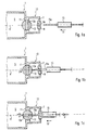
- an incinerator 1 a lock device 3, which has a combustion chamber 5 closes to the environment.
- the lock device 3 comprises one inserted into a first, outer wall section 7 Plastic guide ring 9 (for example made of Teflon), and a arranged in a second, inner wall section 11 Ball valve 13.
- the ball valve 13 is in the closed position in FIG. 1a shown and closes the furnace interior 5 tight towards the environment.
- a fluid channel 13 a of the ball valve 13 as well as a - also circular in cross section - centric Opening 9a in the guide ring 9 are in cross section on the External cross section of a needle 15a of a sampling syringe 15 customized.
- the distance between the opening 9a and the fluid channel 13a of the lock device 3 is selected so that the Syringe needle 15a in the engaged state (see Fig. 1c) intervenes in both at the same time.
- 1a is the hypodermic syringe however, in the standby mode for loading of the incinerator, in front of the opening 9a of the guide ring 9 and aligned with it along a common axis A, shown.
- S1 Injection syringe from this initial state so far advanced along the axis A that the needle 15a in the Opening 9a engages and seals it tightly.
- a second Feed step S2 the sampling syringe 15 along the axis A advanced by a further predetermined feed amount in such a way that the needle 15a in the fluid channel 13a of the ball valve 13 engages. Then by axial pressure P on the syringe plunger (not specifically marked) 15 the sample liquid taken up in this in the Combustion chamber 5 injected.
- This state is in Fig. 1c shown.
- FIG. 2 shows a schematic diagram of an arrangement 100 for removal a wastewater sample from different tanks 101a to 101c and for transferring the sample to an incinerator 103.
- the combustion furnace 103 is charged by means of a loading robot 105, which has a sampling syringe 107 carries and has a coordinate control device 109, the is connected to a PC 111.
- the possible trajectories of the loading robot 105 are shown as dashed lines in the figure Lines drawn and labeled with the number 113 and lead from the containers 101a to 101c to the incinerator 103.
- the sections leading to the containers 101a to 101c of the movement paths 113 are position sensors 115a to 115c assigned, and the leading to the incinerator 103 Section of the trajectory are two position sensors 115d and 115e assigned.
- the position is determined by means of the position sensor the sampling syringe 107 both before the drawing up phase the syringe with wastewater samples from one of the containers as well recorded in the phase of loading the incinerator. In the latter phase are - as is already apparent from the previous Execution results in two position detection steps required, which is why on the leading to the incinerator 103 Section of the movement path 113 provided two position sensors are.
- All position sensors 115a to 115e are inputs of the Coordinate controller 109 connected, and this is on the output side with a drive motor 117 of the loading robot, one with the piston (not designated separately) the syringe motor connected to the sampling syringe 107 119 and a valve actuating motor 121 for actuating the Ball valve 13 (Fig. 1a to 1c) of the incinerator connected.
- the implementation of the invention is not based on that described above Example limited, but also in a variety of modified Executions possible. So the loading of the Incinerator can also be done semi-automatically or manually, and the sample can also be taken directly from one of those to be examined Liquid removed through the fluid channel become.
- the sampling syringe has a hose with the Syringe body connected needle, and only this will - at stationary syringe body - between sample container (s) and Move the incinerator.
- Sampling syringe can also be a differently designed sampling device be provided as long as to cooperate is suitable with the incinerator according to the invention.
- position sensors can also be used in this case be provided as a safety switch with which Damage to the lock device and / or the sampling device be avoided.
Landscapes
- Health & Medical Sciences (AREA)
- Chemical & Material Sciences (AREA)
- Life Sciences & Earth Sciences (AREA)
- Biochemistry (AREA)
- General Physics & Mathematics (AREA)
- Pathology (AREA)
- Physics & Mathematics (AREA)
- Analytical Chemistry (AREA)
- Engineering & Computer Science (AREA)
- General Health & Medical Sciences (AREA)
- Immunology (AREA)
- Combustion & Propulsion (AREA)
- Molecular Biology (AREA)
- Food Science & Technology (AREA)
- Medicinal Chemistry (AREA)
- Sampling And Sample Adjustment (AREA)
- Investigating Or Analyzing Non-Biological Materials By The Use Of Chemical Means (AREA)
- Incineration Of Waste (AREA)
- Regulation And Control Of Combustion (AREA)
Abstract
Description
- Fig. 1a bis 1c
- den Verschlußabschnitt eines Verbrennungsofens in einer Ausführungsform zusammen mit einer als Injektionsspritze ausgeführten Probenahmeeinrichtung in drei Phasen des Beschickungvorgangs in schematischer Darstellung und
- Fig. 2
- ein Funktions-Blockschaltbild einer Ausführungsform einer Gesamt-Beschickungsanordnung.
- 1
- Verbrennungsofen
- 3
- Schleuseneinrichtung
- 5
- Ofeninnenraum
- 7
- erster äußerer Wandungsabschnitt
- 9
- Führungsring
- 9a
- zentrische Öffnung
- 11
- zweiter äußerer Wandungsabschnitt
- 13
- Kugelventil
- 13a
- Fluidkanal
- 15
- Probenahmespritze
- 15a
- Nadel
- 100
- Anordnung zur Entnahme einer Abwasserprobe
- 101a
- Behälter
- 101b
- Behälter
- 101c
- Behälter
- 103
- Verbrennungsofen
- 105
- Beschickungsroboter
- 107
- Probenahmespritze
- 109
- Koordinatensteuereinrichtung
- 111
- PC
- 113
- Bewegungsbahn
- 115a
- Positionsfühler
- 115b
- Positionsfühler
- 115c
- Positionsfühler
- 115d
- Positionsfühler
- 115e
- Positionsfühler
- 117
- Antriebsmotor
- 119
- Spritzenbetätigungsmotor
- 121
- Ventilbetätigungsmotor
- A
- gemeinsame Achse
- R
- Ventilöffnungsrichtung
- S1
- erster Vorschubschritt
- S2
- zweiter Vorschubschritt
Claims (10)
- Verbrennungsofen (1; 103) für die Verbrennung von flüssigen Proben zur Bestimmung von Inhaltsstoffen, insbesondere von Wasser- oder Abwasserproben zur Bestimmung des Kohlenstoffgehalts,
gekennzeichnet durch
eine Schleuseneinrichtung (3) zum Eintrag der Probe mittels einer Probenahmeeinrichtung (15; 107). - Verbrennungsofen nach Anspruch 1,
dadurch gekennzeichnet,
daß die Schleuseneinrichtung (3) eine von der Außenseite des Verbrennungsofens (1) zugängliche, durch Einführung der Probenahmeeinrichtung (15) dicht verschließbare Beschickungsöffnung (9a) und einen der Beschickungsöffnung zum Inneren des Verbrennungsofens hin nachgeordneten steuerbaren Verschluß (13) umfaßt. - Verbrennungsofen nach Anspruch 2,
dadurch gekennzeichnet,
die Beschickungsöffnung (9a) der Schleuseneinrichtung (3) als im Querschnitt kreisförmige, an den Außenquerschnitt eines Eingriffsabschnitts (15a) der Probenahmeeinrichtung (15) angepaßte Öffnung eines elastischen oder elastisch gelagerten Führungsrings (9) ausgebildet ist. - Verbrennungsofen nach Anspruch 2 oder 3,
dadurch gekennzeichnet,
daß der Verschluß (13) ein manuell oder in Abhängigkeit vom Verschlußzustand der Beschickungsöffnung (9a) automatisch gesteuertes Absperrorgan, insbesondere ein Absperrventil oder einen Absperrhahn oder Absperrschieber, aufweist. - Verbrennungsofen nach Anspruch 4,
gekennzeichnet durch
die Ausbildung des Absperrorgans (13) derart, daß sein Öffnungsquerschnitt an den Außenquerschnitt des Eingriffsabschnitts (15a) der Probenahmeeinrichtung (15) angepaßt ist, derart, daß diese mindestens abschnittsweise durch das Absperrorgan, insbesondere bis in den Verbrennungsraum (5) hinein, in den Verbrennungsofen (1) eingeschoben werden kann. - Anordnung (100) zur Entnahme einer flüssigen Probe aus einem Reservoir (101a bis 101c) zu deren Überführung in einen Verbrennungsofen (1; 103) nach einem der vorangehenden Ansprüche,
gekennzeichnet durch
eine Verfahreinrichtung (105) zum Verfahren mindestens eines Abschnitts (15a) der Probenahmeeinrichtung (107; 15) zwischen dem Reservoir und dem Verbrennungsofen und zu deren mindestens abschnittsweise Einführung in die Schleuseneinrichtung (3) des Verbrennungsofens, wobei die Verfahreinrichtung einen elektromotorischen Antrieb (117) und eine Koordinatensteuereinrichtung (109) aufweist. - Anordnung nach Anspruch 6,
dadurch gekennzeichnet,
daß die Schleuseneinrichtung (3) einen, insbesondere elektromotorischen, steuerbaren Antrieb (121) aufweist. - Anordnung nach Anspruch 7,
dadurch gekennzeichnet,
daß die Koordinatensteuereinrichtung (109) zur Einführung mindestens eines Abschnitts (15a) der Probenahmeeinrichtung (15; 107) in den Verbrennungsofen (1; 103) in einem ersten und einem zweiten Schritt (51, 52), insbesondere in ein und derselben Vorschubrichtung, und zur Ausgabe eines Öffnungssteuersignals an den Antrieb (121) der Schleuseneinrichtung (3) nach dem ersten Schritt ausgebildet ist. - Anordnung nach Anspruch 8,
dadurch gekennzeichnet,
daß der Antrieb mindestens einen Schrittmotor umfaßt. - Anordnung nach einem der Ansprüche 6 bis 9,
dadurch gekennzeichnet,
daß der Verfahreinrichtung (105) eine vorbestimmte Bewegungsbahn (113) zugeordnet ist, der in einem dem Verbrennungsofen (103) benachbarten Abschnitt mindestens einen Positionsfühler (115d, 115e) zur Erfassung der Position der Verfahreinrichtung (105) bzw. der Probenahmeeinrichtung (107) bezüglich des Verbrennungsofens aufweist.
Applications Claiming Priority (2)
| Application Number | Priority Date | Filing Date | Title |
|---|---|---|---|
| DE19902277A DE19902277A1 (de) | 1999-01-21 | 1999-01-21 | Verbrennungsofen für die Verbrennung von flüssigen Proben |
| DE19902277 | 1999-01-21 |
Publications (2)
| Publication Number | Publication Date |
|---|---|
| EP1022564A2 true EP1022564A2 (de) | 2000-07-26 |
| EP1022564A3 EP1022564A3 (de) | 2003-07-23 |
Family
ID=7894945
Family Applications (1)
| Application Number | Title | Priority Date | Filing Date |
|---|---|---|---|
| EP00101172A Withdrawn EP1022564A3 (de) | 1999-01-21 | 2000-01-21 | Verbrennungsofen für die Verbrennung von flüssigen Proben |
Country Status (2)
| Country | Link |
|---|---|
| EP (1) | EP1022564A3 (de) |
| DE (2) | DE29924834U1 (de) |
Cited By (2)
| Publication number | Priority date | Publication date | Assignee | Title |
|---|---|---|---|---|
| WO2016091252A3 (de) * | 2014-12-08 | 2016-09-15 | Lar Process Analysers Ag | Analyseanordnung zur wasser- und abwasseranalyse |
| WO2017071696A1 (de) * | 2015-10-30 | 2017-05-04 | Lar Process Analysers Ag | Probenverdünnung |
Family Cites Families (10)
| Publication number | Priority date | Publication date | Assignee | Title |
|---|---|---|---|---|
| DE2606687C3 (de) * | 1976-02-19 | 1978-08-31 | Chemische Werke Huels Ag, 4370 Marl | Verfahren sowie Vorrichtung zur Entnahme einer Probe aus einem unter Druck stehenden Reaktionsgefäß |
| US4968485A (en) * | 1987-09-25 | 1990-11-06 | Shimadzu Corporation | Arrangements for preparative route leading to water analysis |
| DE8715782U1 (de) * | 1987-11-28 | 1988-01-14 | Gerstel, Eberhard, 4330 Mülheim | Probenaufgabe- bzw. -entnahmekopf für Gas oder Flüssigkeit |
| US5062310A (en) * | 1990-03-01 | 1991-11-05 | Jade Systems, Inc. | Probe inlet apparatus and method |
| GB9203642D0 (en) * | 1992-02-19 | 1992-04-08 | Fluid Dynamics Sales Ltd | Carbon analyser |
| JP2541418B2 (ja) * | 1992-03-26 | 1996-10-09 | 株式会社島津製作所 | Poc測定装置 |
| DE4412778C1 (de) * | 1994-04-18 | 1995-07-20 | Elementar Analysensysteme Gmbh | Verfahren und Vorrichtung zur Analyse einer wässrigen Probe |
| US5651940A (en) * | 1995-12-26 | 1997-07-29 | Hitachi Instruments, Inc. | Sealed sample cuvette for volatile solutions |
| DE19616760C2 (de) * | 1996-04-26 | 1999-12-23 | Fraunhofer Ges Forschung | Verfahren und Vorrichtung zur kontinuierlichen Bestimmung gasförmiger Oxidationsprodukte |
| DE19727839A1 (de) * | 1997-06-24 | 1999-01-28 | Lar Analytik Und Umweltmestech | Verfahren zur Bestimmung eines Wasserinhaltsstoffes |
-
1999
- 1999-01-21 DE DE29924834U patent/DE29924834U1/de not_active Expired - Lifetime
- 1999-01-21 DE DE19902277A patent/DE19902277A1/de not_active Withdrawn
-
2000
- 2000-01-21 EP EP00101172A patent/EP1022564A3/de not_active Withdrawn
Cited By (11)
| Publication number | Priority date | Publication date | Assignee | Title |
|---|---|---|---|---|
| WO2016091252A3 (de) * | 2014-12-08 | 2016-09-15 | Lar Process Analysers Ag | Analyseanordnung zur wasser- und abwasseranalyse |
| CN107209161A (zh) * | 2014-12-08 | 2017-09-26 | 拉尔分析仪器有限公司 | 用于分析水和废水的分析系统 |
| CN107209161B (zh) * | 2014-12-08 | 2019-12-31 | 拉尔分析仪器有限公司 | 用于分析水和废水的分析系统 |
| WO2017071696A1 (de) * | 2015-10-30 | 2017-05-04 | Lar Process Analysers Ag | Probenverdünnung |
| KR20180075618A (ko) * | 2015-10-30 | 2018-07-04 | 라 프로세스 아날라이저스 아게 | 샘플 희석 |
| CN108431597A (zh) * | 2015-10-30 | 2018-08-21 | 拉尔分析仪器有限公司 | 样品稀释 |
| US20180283996A1 (en) * | 2015-10-30 | 2018-10-04 | Lar Process Analysers Ag | Sample dilution |
| KR102202784B1 (ko) | 2015-10-30 | 2021-01-13 | 라 프로세스 아날라이저스 아게 | 샘플 희석 |
| RU2750990C2 (ru) * | 2015-10-30 | 2021-07-07 | Лар Процесс Анализерс Аг | Разбавление пробы |
| EP3913365A1 (de) * | 2015-10-30 | 2021-11-24 | LAR Process Analysers AG | Probenverdünnung |
| US11199481B2 (en) * | 2015-10-30 | 2021-12-14 | Lar Process Analysers Ag | Sample dilution |
Also Published As
| Publication number | Publication date |
|---|---|
| EP1022564A3 (de) | 2003-07-23 |
| DE29924834U1 (de) | 2005-12-29 |
| DE19902277A1 (de) | 2000-07-27 |
Similar Documents
| Publication | Publication Date | Title |
|---|---|---|
| DE69726094T2 (de) | Probenfläschen und Verschluss zur Anwendung in der Gasanalyse | |
| DE69314462T2 (de) | Abdichtbarer behälter zum konservieren und behandeln analytischer proben | |
| CH654416A5 (de) | Verfahren und vorrichtung zur quantitativen analyse von bestandteilen in diskreten fluessigkeitsproben. | |
| WO1985003773A1 (fr) | Installation de prise d'echantillons | |
| EP1984729A1 (de) | Verfahren und vorrichtung zum ansaugen eines flüssigkeitsvolumens, insbesondere zur entnahme einer probe zur analyse mittels einer flüssigkeitschromatographievorrichtung | |
| EP2194369A1 (de) | Probenahme-Einrichtung | |
| DE69602851T2 (de) | Multifunktions-ventil | |
| DE2851058C3 (de) | Vorrichtung zur automatischen Messung der Atomabsorption gasförmiger Meßproben | |
| EP0357998B1 (de) | Verfahren für eine sterile Handhabung von strömungsfähigen Fermenterproben sowie Vorrichtung zur Durchführung des Verfahrens. | |
| EP1022564A2 (de) | Verbrennungsofen für die Verbrennung von flüssigen Proben | |
| EP1641564B1 (de) | Verwendung eines einwegbehälters, mikrofluidische vorrichtung und verfahren zur bearbeitung von molekülen | |
| EP0071091A1 (de) | Probengeber für Gaschromatographen | |
| DE1598267B2 (de) | Einrichtung fur Probenahmen in Analysatoren | |
| DE69218506T2 (de) | Verfahren und Vorrichtung zum Transfer eines in einem geschlossener Behälter enthaltenen Fluidums aus einer dichten Umgebung | |
| DE2748685C2 (de) | Vorrichtung zum Erzeugen und Überführen einer gasförmigen Meßprobe | |
| DE4023841A1 (de) | Einrichtung zur entnahme von gas- und/oder fluessigkeitsproben aus einem sicherheitsbehaelter von kernkraftwerken | |
| DE19925658C2 (de) | Vorrichtung zur automatischen Probenvorbereitung und deren Verwendung | |
| DE3134722C2 (de) | ||
| DE1940062U (de) | Probenabfuellvorrichtung fuer eine fluessigkeitsentnahmeanlage. | |
| DE3104617A1 (de) | Analysengeraet zur messung von fluessigkeitsproben und einrichtung zur einstellung eines bestimmten betriebszustandes desselben | |
| DE2060559B2 (de) | Vorrichtung zum Mischen von zumindest zwei Flüssigkeiten in einem bestimmten Verhältnis und zum Abgeben einer bestimmten Menge der Mischung | |
| EP0006581B1 (de) | Vorrichtung zur kontaminationsfreien Probenahme einer Flüssigkeit aus einem Tank | |
| DE2005841A1 (de) | Probenentnahmeventil | |
| DE3132638C2 (de) | ||
| DE2846682A1 (de) | Verfahren und vorrichtung fuer die photometrische analyse von fluessigkeiten |
Legal Events
| Date | Code | Title | Description |
|---|---|---|---|
| PUAI | Public reference made under article 153(3) epc to a published international application that has entered the european phase |
Free format text: ORIGINAL CODE: 0009012 |
|
| AK | Designated contracting states |
Kind code of ref document: A2 Designated state(s): AT BE CH CY DE DK ES FI FR GB GR IE IT LI LU MC NL PT SE |
|
| AX | Request for extension of the european patent |
Free format text: AL;LT;LV;MK;RO;SI |
|
| PUAL | Search report despatched |
Free format text: ORIGINAL CODE: 0009013 |
|
| AK | Designated contracting states |
Designated state(s): AT BE CH CY DE DK ES FI FR GB GR IE IT LI LU MC NL PT SE |
|
| AX | Request for extension of the european patent |
Extension state: AL LT LV MK RO SI |
|
| AKX | Designation fees paid | ||
| REG | Reference to a national code |
Ref country code: DE Ref legal event code: 8566 |
|
| STAA | Information on the status of an ep patent application or granted ep patent |
Free format text: STATUS: THE APPLICATION IS DEEMED TO BE WITHDRAWN |
|
| 18D | Application deemed to be withdrawn |
Effective date: 20040202 |