EP1022570A2 - Failsafe monitoring system for potentiometers - Google Patents
Failsafe monitoring system for potentiometers Download PDFInfo
- Publication number
- EP1022570A2 EP1022570A2 EP00101062A EP00101062A EP1022570A2 EP 1022570 A2 EP1022570 A2 EP 1022570A2 EP 00101062 A EP00101062 A EP 00101062A EP 00101062 A EP00101062 A EP 00101062A EP 1022570 A2 EP1022570 A2 EP 1022570A2
- Authority
- EP
- European Patent Office
- Prior art keywords
- potentiometer
- wiper
- resistance
- fault
- switch
- Prior art date
- Legal status (The legal status is an assumption and is not a legal conclusion. Google has not performed a legal analysis and makes no representation as to the accuracy of the status listed.)
- Granted
Links
- 238000012544 monitoring process Methods 0.000 title claims abstract description 34
- 238000012360 testing method Methods 0.000 claims abstract description 43
- 238000000034 method Methods 0.000 claims description 16
- 238000005259 measurement Methods 0.000 claims description 8
- 230000008878 coupling Effects 0.000 claims 5
- 238000010168 coupling process Methods 0.000 claims 5
- 238000005859 coupling reaction Methods 0.000 claims 5
- 238000002485 combustion reaction Methods 0.000 description 5
- 230000006870 function Effects 0.000 description 3
- 230000001052 transient effect Effects 0.000 description 3
- 230000005669 field effect Effects 0.000 description 2
- 231100001261 hazardous Toxicity 0.000 description 2
- 230000032683 aging Effects 0.000 description 1
- 230000001419 dependent effect Effects 0.000 description 1
- 238000001514 detection method Methods 0.000 description 1
- 230000006866 deterioration Effects 0.000 description 1
- 238000011161 development Methods 0.000 description 1
- 230000018109 developmental process Effects 0.000 description 1
- 238000012545 processing Methods 0.000 description 1
- 238000006467 substitution reaction Methods 0.000 description 1
Images




Classifications
-
- G—PHYSICS
- G01—MEASURING; TESTING
- G01R—MEASURING ELECTRIC VARIABLES; MEASURING MAGNETIC VARIABLES
- G01R31/00—Arrangements for testing electric properties; Arrangements for locating electric faults; Arrangements for electrical testing characterised by what is being tested not provided for elsewhere
- G01R31/28—Testing of electronic circuits, e.g. by signal tracer
- G01R31/282—Testing of electronic circuits specially adapted for particular applications not provided for elsewhere
- G01R31/2829—Testing of circuits in sensor or actuator systems
-
- G—PHYSICS
- G01—MEASURING; TESTING
- G01R—MEASURING ELECTRIC VARIABLES; MEASURING MAGNETIC VARIABLES
- G01R27/00—Arrangements for measuring resistance, reactance, impedance, or electric characteristics derived therefrom
- G01R27/02—Measuring real or complex resistance, reactance, impedance, or other two-pole characteristics derived therefrom, e.g. time constant
- G01R27/08—Measuring resistance by measuring both voltage and current
Definitions
- This invention relates to a method and apparatus for monitoring in a fail-safe manner potentiometers used in critical control operations. More particularly, the invention relates to monitoring in a fail safe manner the characteristics of potentiometers where the detected control value from a control potentiometer is a critical safety factor in a control system.
- a system such as a non-flow compensating fuel-air ratio control system controlling a large boiler and using potentiometer settings to control the position of valves and dampers is a system where monitoring of the control potentiometers is a critical life safety factor.
- Control of actuators for a valve and/or damper in such a combustion system in the past has been accomplished with a motor driven mechanical cam.
- Such a device has mechanical limits to provide for fail-safe control of the valves and dampers. Due to the mechanical linkages and the limits placed on the mechanical linkages, the fuel-air ratios were never permitted to enter a hazardous range of operation.
- a control potentiometer In today's environment with microprocessor control and electronic sensing of desired position and electronic feedback to control valves, an electronic failure of a control potentiometer can create a fuel-air ratio in a combustion system that is hazardous. Furthermore, because of the harsh operating environment and because of aging, a control potentiometer's resistance may vary. Also, the resistance at the potentiometer's connector terminals may vary, and the wiper resistance on the potentiometer may change. Any one of these changes or all these changes together can create a situation where an incorrect control signal is provided by the potentiometer monitoring circuit to a controlling microprocessor that controls critical elements such as fuel-air valves. What is needed is a fail-safe monitoring system for potentiometers.
- the above problems with monitoring control potentiometers have been solved by using a computer processor and a monitor interface circuit connected between the potentiometer and the processor, and then monitoring through the monitor interface circuit the potentiometer, its terminals and its wiper for faults.
- the monitor interface circuit itself is tested so that a fault in the potentiometer or a fault in the monitor interface circuit is detected to prevent the control potentiometer and monitor interface circuit from producing an incorrect control signal.
- the monitoring is accomplished by measuring changes in the full potentiometer resistance from a predetermined value.
- the changes are compared against boundary limits to detect whether a change is inside or outside the boundary limits.
- a fault in the control potentiometer is indicated when a change is outside the boundary limits.
- the monitoring also monitors wiper resistance of the potentiometer.
- the wiper resistance of the control potentiometer is measured, and the wiper resistance is compared against a fault threshold to detect if the wiper resistance has passed the fault threshold.
- a fault in the wiper of the control potentiometer is indicated when the wiper resistance has passed the threshold.
- the testing of the monitor interface circuit is accomplished by measuring idle signals applied to the full potentiometer and to the wiper when the monitor interface circuit is an idle state.
- the idle signals are compared against an expected signal to detect if the idle signals are within a predetermined tolerance range of the expected signal.
- a fault in the monitor interface circuit is indicated if the idle signals are outside the predetermined tolerance range.
- control potentiometer 10 is located with the actuator 12 associated with the potentiometer. Adjustments of the wiper 14 produces a voltage across line AD2 to analog digital converters 16. The digital value of this voltage is input to the microprocessor 18 through the I/O controller 20.
- the microprocessor 18 contains the control program for controlling actuators, including actuator 12, by providing a control signal out through I/O controller 20 over a control line 22.
- the actuators are installed, the potentiometer is installed and the control system is initialized with initial values for the potentiometer 10.
- microprocessor 18 controls switch drivers 24 to switch field effect transistor 26 "ON” and field effect transistor 28 “OFF.” With transistor 26 ON, the current source 30 drives a current "i" through potentiometer 10. Depending on the position of the wiper 14, a voltage is fed back on line AD2 as a control voltage for the microprocessor 18. This constitutes the normal operation of the potentiometer 10 where the position of wiper 14 on the potentiometer results in a control signal used by microprocessor 18 to control actuator 12.
- microprocessor 18 With an incorrect pot signal feedback to microprocessor 18, the microprocessor will send an incorrect actuator control signal over the control line 22 to actuator 12. A bad actuator control signal could produce a dangerous adjustment of actuator 12. Accordingly, the microprocessor 18 also performs fail-safe monitoring operations to monitor failure of the potentiometer 10 or monitor interface circuit 15, and these logical operations are illustrated in Figure 2.
- the embodiments of the invention described herein include logical operations when monitoring the control potentiometer.
- the logical operations of the present invention may be implemented (1) as a sequence of computer-implemented steps running on a microprocessor in a controller, and (2) as interconnected logic modules within the controller.
- the implementation is a matter of choice, dependent on the performance requirements of the controller. Accordingly, the logical operations making up the embodiments of the invention described herein are referred to variously as operations, steps or modules.
- the logical operations shown in Figures 2-5 will be described in reference to these figures and also Figure 1.
- the monitoring operations consist of three modules -- a total resistance test module 32, a wiper resistance test module 34, and an interface circuit test module 36. These test modules perform the monitoring operations whereby a faulty interface circuit or a faulty potentiometer is detected before a dangerous control adjustment is made to an actuator.
- the total resistance test module 32 is designed to monitor the total resistance across potentiometer 10. A total pot resistance value is initially determined for potentiometer 10 during commissioning. By monitoring changes in this total pot resistance against the boundary limits for an operative potentiometer, a faulty potentiometer or an increase in resistance of wiring terminals c1 a1 or c3 a3 may be detected.
- Wiper resistance test module 34 is testing for changes in the wiper resistance which is the resistance through the wiper 14 to ground. While the wiper selected pot resistance Rp may change with age or environment, it is more likely that changes in wiper resistance will be due to changes in wiper contact resistance or changes in resistance across terminals c2 a2 and c3 a3. Wiper resistance in this embodiment is tested against a failure threshold which guarantees that wiper resistance will not cause an incorrect control value to be passed back to microprocessor. If the wiper resistance exceeds the fault threshold, then the potentiometer is indicated as having a faulty wiper resistance and the controller shuts down the system being controlled.
- the monitoring operations also include the interface circuit test module 36.
- the interface circuit module 36 operates to test the components in the monitor interface circuit 15. The correct functioning of switches 26 and 28 as well as the transient protection diodes 38 and 42.
- a failure threshold for the monitor interface circuit is stored in memory 19 or provided as control data to microprocessor 18. If the monitor interface circuit detects signals outside of a tolerance threshold during idle mode when the potentiometer is not being driven by the circuit, the monitor interface circuit will be indicated as faulty.
- FIG 3 illustrates the logical operations performed by the total resistance test module 32 in Figure 2.
- the total resistance test begins in logical operation 50 which provides a current drive through potentiometer 10. This is accomplished by microprocessor 18 acting through switch drivers 24 to turn ON transistor 26 and turn OFF transistor 28. With transistor 26 ON, the current source 30 provides a current "i" through potentiometer 10. With transistor 28 (switch 2) turned OFF, reference voltage applied through resistor 46 is blocked. Accordingly, the only voltage on line AD1 will be due to the current "i” creating a voltage drop across resistor 48, terminal c1 a1, potentiometer total resistance R tot and the resistance cross c3 a3. Operation 52 in Figure 3 measures the voltage at line AD1.
- Analog digital converter 16 converts this voltage into a digital value which is provided through the input/output control 20 to the microprocessor 18.
- the digital value at AD1 may then be used directly as a test value or the microprocessor 18 can divide the digital value by a known value for the current "i" from current source 30 to determine the resistance from node 47 to ground. With the resistance from node 47 to ground known, then the resistive value R2 of resistance 48 may be subtracted to determine the total resistance Rtot of the potentiometer 10 plus the resistance of terminals c1 a1 and c3 a3.
- the voltage on AD1 (V AD1 ) is sensed while SW1 is ON and SW2 is OFF.
- V AD1 is converted to a digital value by analog to digital converter 16. From the value for V AD1 and knowing a predetermined value for current "i" from current source 30, microprocessor 18 divides V AD1 by "i" to determine an AD1 resistance between node 47 and ground. During commissioning, this AD1 resistance should be Rtot plus R2 since resistance of terminals c1 a1 and c3 a3 should be negligibly small compared to Rtot. By subtracting R2 from the AD1 resistance, R tot is determined. R tot value is stored in memory as well as the initial value for V AD1 at commissioning.
- decision operation 54 detects whether the V AD1 is within limits.
- the limits are set based upon (1) an initial value for the total pot resistance R tot , (2) expected temperature excursions creating resistance changes in the potentiometer 10 and (3) the tolerance of the components, resistor 48 and potentiometer 10. The initial value for R tot is determined at commissioning as described above. If V AD1 is within limits, the test is completed and the logical operation is returned to the monitor main operation flow in Figure 2. If V AD1 is out of limits, the operation flow branches NO from decision operation 54. Operation 56 indicates a potentiometer fault, and the operation flow returns to the monitor operation flow in Figure 2.
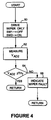
- FIG. 4 shows the logical operations performed by the wiper resistance test module 34 of Figure 2.
- the wiper resistance test begins in logical operation 60.
- Logical operation 60 provides a voltage drive only through the wiper 14 and the resistance R P of the portion of the potentiometer 10 between wiper 14 and ground. This is accomplished by the microprocessor 18 acting through switch driver 24 to turn OFF transistor 26 (switch 1) and to turn ON transistor 28 (switch 2).
- the reference voltage V ref is thus applied across resistor 46, resistor 49 and resistance Rp to ground.
- there will be some amount of small resistance due to terminals c2 a2 and c3 a3.
- Line AD2 connects node 45 back to analog digital converter 16.
- the voltage V AD2 at node 45 is a measure of the resistance between node 45 and ground.
- the resistive values for resistor 46 and 49 are known. Accordingly, the voltage dividing action between resistor R1 and the resistance across R3, terminal c2 a2, wiper contact resistance, resistance Rp and terminal c3 a3 define the voltage of V AD2 .
- This voltage is convened by the analog digital converter 16 to a digital value applied to the microprocessor 18 for analysis.
- the resistance R P can be computed from the resistance R tot based on the position of the wiper. For example if R tot is 5k ohms, and the wiper is positioned 2/5ths from the bottom potentiometer 10, then R P is 2k ohms. Changes in R P can be monitored by computing a value for R P based on the voltage drop across resistor 46 and resistor 49 plus R P since the values R1 and R3 are known and assuming wiper contact resistance and resistance across terminals c2 a2 and c3 a3 are negligible.
- the microprocessor can compute the combined resistance across terminals c2 a2 plus wiper contact resistance plus resistance R P plus resistance across terminal c3 a3.
- a fault threshold for combined resistance is used by the computer to determine when this combined threshold is too high.
- the microprocessor measures the voltage V AD2 (voltage on line AD2). This voltage is converted to a digital value and the microprocessor in decision operation 64 compares V AD2 value against a voltage threshold value. Decision operation 64 is testing the voltage V AD2 against a predetermined fault threshold.
- the fault threshold is based upon observed changes in V AD2 due to changes in the wiper contact resistance and based upon different values of R P .
- Figure 6 is a graph of digital values for V AD2 as a function of wiper contact resistance for three different values of R P . This graph indicates that as wiper contact resistance increases, it rapidly swamps out changes in V AD2 due to changes in R P . Therefore in the example of Figure 6 a fault threshold value of 2500 is a good choice.
- the operation flow branches NO from decision operation 64 to operation 66.
- Operation 66 indicates a wiper fault and the logical operation returns to the main monitor program in Figure. 2. If the voltage V AD2 is less than the fault threshold, the wiper contact resistance is within an acceptable limit, and the operation flow branches YES from decision operation 64 to return to the main monitor operation flow in Figure 2.
- FIG. 5 illustrates the logical operations of the interface circuit test module 36 in Figure 2.
- the interface circuit test begins at logical operation 70 in Figure 5 which inhibits all current or voltage drive to the potentiometer 10 from the monitor interface circuit 15, i.e., the idle state. This is accomplished by the microprocessor 18 acting through the switch drivers 24 to turn OFF both transistor 26 (switch 1) and transistor 28 (switch 2). This isolates the current source 30 from the potentiometer and also isolates the voltage Vref from the potentiometer 10. In the idle state, the expectation then is that the voltage at node 47 and node 45 should be zero volts plus or minus a very minor tolerance.
- V AD1 sensed by microprocessor 18 through analog digital converter 16 in out of tolerance.
- Operation 72 in Figure 5 measures the voltage on line AD1.
- Operation 72 also measures the voltage V AD2 on line AD2 which is the voltage at node 45. This voltage should be near zero unless transistor 28 has failed to isolate Vref from the wiper or diode 42 has failed.
- the value for V AD2 should be at zero plus or minus a very minor tolerance value for leakage across the back-biased junctions of transistor 28 and diode 42.
- decision operation 74 tests each of these voltage values against zero volts, plus or minus, a fault tolerance.
- the fault tolerance is based on the accuracy of the converter 16 and the quality of transistor 26 and transistor 28 at the maximum operating temperature of circuit 15 in Figure 1. If decision operation 74 detects that the voltage of both V AD1 and V AD2 are within the tolerance range of zero volts, then the logical operation branches YES and returns to the monitor operation flow in Figure 2. If decision operation 74 detects that either the voltage at AD1 or AD2 depart from zero volts by more than the tolerance, then the logical operations branch NO from decision operation 74 to operation 76. Operation 76 then indicates a monitor interface circuit fault. The monitor interface circuit 15 may then be replaced or the entire controller including microprocessor can be replaced.
- the interface circuit test does not detect a failure of diode 40 or diode 44 as these diodes are connected to ground.
- the diodes in the monitor interface circuit are provided for transient signal protection. The diodes prevent the voltage at nodes 45 and 47 from going above V CC or below ground. Diodes 40 and 44 could be removed with some risk to the circuit that it would be damaged by a negative transient. Alternatively, leakage through diodes 40 and 44 might be detected by the above described test for wiper contact resistance R CR . If R CR is tested and for multiple positions of the wiper and particularly where R P is near zero, a change in the calculated value for R CR as R P goes to zero will indicate a fault in diode 40 or diode 44.
- test modules 32, 34 and 36 are rearranged so that a wiper resistance test is performed as a first test operation or so that the interface circuit test operation is performed as a first operation.
- the sequence of the tests is a matter of choice.
- the monitor program in another embodiment terminates the test operations upon detection of first fault and returns the program flow to the main program controlling the combustion system.
- the fail-safe monitoring would be performed frequently. Depending upon safety requirements, the monitor operations might be performed hourly or every minute. In a multitasking program operation, the operations could be performed in parallel with normal control operations.
Landscapes
- Physics & Mathematics (AREA)
- General Physics & Mathematics (AREA)
- Electromagnetism (AREA)
- Engineering & Computer Science (AREA)
- General Engineering & Computer Science (AREA)
- Testing Of Short-Circuits, Discontinuities, Leakage, Or Incorrect Line Connections (AREA)
- Measurement Of Resistance Or Impedance (AREA)
Abstract
Description
Claims (25)
- An apparatus for fault monitoring a potentiometer having a first terminal and a second terminal, said second terminal being coupled to a common potential, said apparatus comprising:a monitor interface including a first switch for coupling current to said first terminal of said potentiometer;a first measurement line coupled to a first node between said first switch and said first terminal for measuring voltage across said potentiometer between said first node and said common potential;a first switch driver line coupled to said first switch for controlling current through said potentiometer.
- The apparatus of claim 1 further comprising:an analog-to-digital converter coupled to said first measurement line for converting said measured voltage into a digital value; anda microcontroller coupled to said analog-to-digital converter for indicating a fault if said digital value exceeds a predetermined limit.
- The apparatus of claim 1 further comprising:a switch driver coupled to said switch driver line for driving a switch voltage to said first switch; anda microcontroller coupled to said switch driver for controlling said switch voltage applied to said first switch.
- The apparatus of claim 1 further comprising:a memory for storing a predetermined limit associated with an initial total resistance of said potentiometer; anda fault signal for indicating a potentiometer fault if said measured voltage exceeds said predetermined limit.
- The apparatus of claim 1 wherein said first terminal is a wiper terminal of said potentiometer and said measured voltage is associated with a wiper selected pot resistance, whereina memory stores a predetermined limit associated with said wiper selected pot resistance; and whereina fault signal indicates a potentiometer fault if said measured voltage exceeds said predetermined limit.
- The apparatus of claim 1 wherein said monitor interface further includes a second switch for coupling current to a wiper terminal of said potentiometer, and further comprising:a second measurement line coupled to a second node between said second switch and said wiper terminal for measuring a second voltage across said potentiometer between said second node and said common potential; anda second switch driver line coupled to said second switch for controlling current through said potentiometer.
- The apparatus of claim 6 wherein total resistance of said potentiometer is monitored when said first switch is switched on to allow current to flow through said first node to said potentiometer and said second switch is switched off to prevent current from flowing through said second node to said potentiometer.
- The apparatus of claim 6 wherein wiper selected pot resistance of said potentiometer is monitored when said first switch is switched off to prevent current from flowing through said first node to said potentiometer and said second switch is switched on to allow current to flow through said second node to said potentiometer.
- The apparatus of claim 6 wherein said monitor interface is monitored when said first and second switches are switched off to prevent current from flowing through said first and second nodes to said potentiometer, and whereina fault signal indicates a potentiometer fault if said first or second measured voltage exceeds a predetermined limit.
- A method for fault monitoring a potentiometer having a first terminal and a second terminal, and a wiper terminal, said method comprising:coupling a first switch and a first measurement node between a current source and said first terminal;coupling said second terminal to a common potential;driving said switch to control current to said potentiometer through said first terminal; andmeasuring a first voltage between said first measurement node and said common potential.
- The method of claim 10 further comprising:coupling a second switch and a second measurement node between a current source and said wiper terminal;driving said second switch to control current to said potentiometer through said wiper terminal; andmeasuring a second voltage between said second measurement node and said common potential.
- The method of claim 11 further comprising:monitoring total resistance of said potentiometer when said first switch is switched on to allow current to flow through said first node to said potentiometer and said second switch is switched off to prevent current from flowing through said second node to said potentiometer.
- The method of claim 11 further comprising:monitoring a total resistance of said potentiometer when said first switch is switched off to prevent current from flowing through said first node to said potentiometer and said second switch is switched on to allow current to flow through said second node to said potentiometer.
- The method of claim 11 further comprising:monitoring a total resistance of said potentiometer when said first and second switches are switched off to prevent current from flowing through said first and second nodes to said potentiometer,indicating a potentiometer fault if said first or second voltage exceeds a predetermined limit.
- An apparatus for fault monitoring a potentiometer, said apparatus comprising:means for controlling current through said potentiometer coupled to a current source;means for measuring a voltage across said potentiometer; andmeans for detecting a fault in said potentiometer based on said measured voltage.
- The apparatus of claim 15 further comprising:means for monitoring a fault in a monitor interface coupled to said potentiometer.
- The apparatus of claim 15 further comprising:means for indicating said fault responsive to said means for detecting.
- A method for fail-safe monitoring of a control potentiometer in a controller having a processor and a monitor interface circuit between the control potentiometer and the processor, said method comprising the steps of:monitoring through the monitor interface circuit the potentiometer, its terminals and its wiper for faults; andtesting the monitor interface circuit itself, whereby a fault in the potentiometer or a fault in the monitor interface circuit is detected to prevent the control potentiometer and monitor interface circuit from producing an incorrect control signal.
- The method of claim 18 wherein said monitoring step further comprises the steps of:measuring changes in the full potentiometer resistance from a predetermined value;comparing the changes against boundary limits to detect whether a change is inside or outside the boundary limits; andindicating a fault in the control potentiometer when said comparing step detects a change is outside the boundary limits.
- The method of claim 19 wherein said measuring step comprises the steps of:driving a current across the potentiometer;measuring a full pot voltage across the potentiometer and terminals connecting the potentiometer to the monitor interface circuit; andcomputing changes in full pot voltage from a predetermined value for full pot voltage.
- The method of claim 22 wherein said monitoring step further comprises the steps of:measuring the wiper resistance of the control potentiometer;comparing the wiper resistance against a fault threshold to detect if the wiper resistance has passed the fault threshold;indicating a fault in the control potentiometer when said step of comparing wiper resistance detects the wiper resistance has passed the threshold;
and wherein said testing step further comprises the steps of:measuring idle signals applied to the full potentiometer and to the wiper when the monitor interface circuit is an idle state;comparing the idle signals against an expected signal to detect if the signals are within a predetermined tolerance range of the expected signal;indicating a fault in the monitor interface circuit if said step of comparing signals detects the idle signals are outside the predetermined tolerance range. - The method of claim 18 wherein said monitoring step comprises the steps of:measuring the wiper resistance of the control potentiometer;comparing the wiper resistance against a fault threshold to detect if the wiper resistance has passed the fault threshold; andindicating a fault in the control potentiometer when said step of comparing wiper resistance detects the wiper resistance has passed the threshold.
- The method of claim 22 wherein said measuring step comprises the steps of:applying a voltage drive to the wiper of the potentiometer;measuring a voltage drop across the wiper contact and wiper selected potentiometer resistance;converting the voltage drop to a wiper resistance value and providing the wiper resistance value to said comparing step as the wiper resistance.
- The method of claim 22 wherein said measuring step comprises the steps of:applying a voltage drive to the wiper of the potentiometer;measuring a voltage drop across the wiper contact and wiper selected potentiometer resistance;converting the voltage drop to a wiper resistance value;computing a wiper contact resistance from the wiper resistance value and providing the wiper contact resistance to said comparing step as the wiper resistance.
- The method of claim 18 wherein said testing step further comprises the steps of:measuring idle signals applied to the full potentiometer and to the wiper when the monitor interface circuit is an idle state;comparing the idle signals against an expected signal to detect if the signals are within a predetermined tolerance range of the expected signal; andindicating a fault in the monitor interface circuit if said step of comparing signals detects the idle signals are outside the predetermined tolerance range.
Applications Claiming Priority (2)
| Application Number | Priority Date | Filing Date | Title |
|---|---|---|---|
| US09/235,176 US6181141B1 (en) | 1999-01-22 | 1999-01-22 | Failsafe monitoring system for potentiometers and monitor interface |
| US235176 | 1999-01-22 |
Publications (3)
| Publication Number | Publication Date |
|---|---|
| EP1022570A2 true EP1022570A2 (en) | 2000-07-26 |
| EP1022570A3 EP1022570A3 (en) | 2003-01-29 |
| EP1022570B1 EP1022570B1 (en) | 2004-12-29 |
Family
ID=22884423
Family Applications (1)
| Application Number | Title | Priority Date | Filing Date |
|---|---|---|---|
| EP00101062A Expired - Lifetime EP1022570B1 (en) | 1999-01-22 | 2000-01-20 | Failsafe monitoring system for potentiometers |
Country Status (5)
| Country | Link |
|---|---|
| US (1) | US6181141B1 (en) |
| EP (1) | EP1022570B1 (en) |
| AU (1) | AU1353100A (en) |
| CA (1) | CA2296939A1 (en) |
| DE (1) | DE60016984T2 (en) |
Cited By (6)
| Publication number | Priority date | Publication date | Assignee | Title |
|---|---|---|---|---|
| EP1494098A1 (en) * | 2003-07-04 | 2005-01-05 | Siemens Aktiengesellschaft | Control device for safety engineering and control method |
| DE102005048601B3 (en) * | 2005-10-06 | 2007-04-05 | Pilz Gmbh & Co. Kg | Position indicator e.g. potentiometer, evaluating device for safety switching device, has microcontrollers finding measuring quantities representative for indicator`s partial impedances, and having outputs assigned with high/low potential |
| EP1887368A1 (en) | 2006-08-10 | 2008-02-13 | Honeywell International Inc. | Circuit and method for determining potentionmeter wiper resistance |
| US8447555B2 (en) | 2009-08-10 | 2013-05-21 | Abb Technology Ag | Method for increasing the availability of displacement/position measuring systems on the basis of potentiometers with a slider tap |
| CN106646088A (en) * | 2016-11-09 | 2017-05-10 | 珠海格力电器股份有限公司 | Port fault detection circuit |
| EP4538721A4 (en) * | 2022-06-22 | 2025-10-29 | China Nuclear Power Operations Co Ltd | DEVICE FOR MEASURING JOINT RESISTANCE |
Families Citing this family (9)
| Publication number | Priority date | Publication date | Assignee | Title |
|---|---|---|---|---|
| EP1447670A1 (en) * | 2003-02-12 | 2004-08-18 | Dialog Semiconductor GmbH | Sensor read out |
| DE102009035126B4 (en) * | 2009-07-29 | 2016-06-02 | Abb Technology Ag | Method for increasing the availability of displacement / position measuring systems based on wiper-tipped potentiometers |
| EP2511719A1 (en) * | 2011-04-15 | 2012-10-17 | Siemens Aktiengesellschaft | Method for determining a malfunction of a potentiometer |
| JP5843663B2 (en) * | 2012-03-05 | 2016-01-13 | アズビル株式会社 | Potentiometer degradation diagnosis method |
| US9429614B2 (en) * | 2012-12-31 | 2016-08-30 | Schneider Electric USA, Inc. | Open potentiometer detection system |
| US10158308B2 (en) * | 2016-06-17 | 2018-12-18 | Semiconductor Components Industries, Llc | Identifying voltage to prevent motor integrated circuit damage |
| CN111263895B (en) * | 2017-10-23 | 2022-02-22 | 阿尔卑斯阿尔派株式会社 | Abnormality detection device and abnormality detection method |
| CN118719828B (en) * | 2023-03-31 | 2026-04-10 | 宝山钢铁股份有限公司 | Fault diagnosis device for high-voltage system of thickness gauge |
| CN117169798B (en) * | 2023-08-23 | 2025-06-13 | 台山核电合营有限公司 | A device and method for detecting performance of a potentiometer of an electric actuator |
Family Cites Families (12)
| Publication number | Priority date | Publication date | Assignee | Title |
|---|---|---|---|---|
| US3852665A (en) * | 1972-02-17 | 1974-12-03 | Bunker Ramo | Apparatus for testing potentiometers |
| DE3522775A1 (en) * | 1985-06-26 | 1987-01-08 | Daimler Benz Ag | Device for determining the contact resistance on the slider of a potentiometer |
| DE3621937A1 (en) | 1986-06-30 | 1988-01-07 | Bosch Gmbh Robert | MONITORING DEVICE FOR AN ELECTRONIC CONTROL DEVICE IN A MOTOR VEHICLE |
| US4866363A (en) | 1987-09-21 | 1989-09-12 | Honeywell Inc. | Fail-safe potentiometer feedback system |
| DE3826937A1 (en) * | 1988-08-09 | 1990-02-15 | Vdo Schindling | METHOD AND CIRCUIT ARRANGEMENT FOR MONITORING THE TRANSITION RESISTANCE IN A POTENTIOMETER serving as a position encoder |
| DE3918695C1 (en) * | 1989-06-08 | 1990-09-13 | Digi-Table Thielen Gmbh & Co Kg, 4300 Essen, De | Resistance measuring circuit with differential amplifier - has voltage measurement device with input differential amplifier, and constant current source |
| US4987372A (en) * | 1989-08-01 | 1991-01-22 | Lutron Electronics Co., Inc. | Potentiometer state sensing circuit |
| DE4116603A1 (en) | 1991-05-22 | 1992-11-26 | Vdo Schindling | CIRCUIT ARRANGEMENT FOR MONITORING THE CONTACT BETWEEN THE RESISTANCE TRACK AND THE GRINDER OF A POTENTIOMETER |
| DE4322472B4 (en) * | 1993-07-06 | 2006-03-09 | Siemens Ag | Circuit arrangement for monitoring a position transmitter |
| FR2735871B1 (en) * | 1995-06-23 | 1997-07-25 | Renault | METHOD AND DEVICE FOR DIAGNOSING THE OPERATION OF A POTENTIOMETRIC TYPE SENSOR |
| US5812411A (en) * | 1995-07-14 | 1998-09-22 | Calabrese; Joseph S. | Tapped variable potentiometer resistor with current sense and safety circuit |
| EP0759558A3 (en) * | 1995-08-18 | 1997-10-01 | Siemens Ag | Test method for an analog input channel of an analog signal detection circuit and the corresponding analog signal detection circuit |
-
1999
- 1999-01-22 US US09/235,176 patent/US6181141B1/en not_active Expired - Lifetime
-
2000
- 2000-01-20 DE DE60016984T patent/DE60016984T2/en not_active Expired - Fee Related
- 2000-01-20 EP EP00101062A patent/EP1022570B1/en not_active Expired - Lifetime
- 2000-01-21 CA CA002296939A patent/CA2296939A1/en not_active Abandoned
- 2000-01-24 AU AU13531/00A patent/AU1353100A/en not_active Abandoned
Cited By (11)
| Publication number | Priority date | Publication date | Assignee | Title |
|---|---|---|---|---|
| EP1494098A1 (en) * | 2003-07-04 | 2005-01-05 | Siemens Aktiengesellschaft | Control device for safety engineering and control method |
| DE102005048601B3 (en) * | 2005-10-06 | 2007-04-05 | Pilz Gmbh & Co. Kg | Position indicator e.g. potentiometer, evaluating device for safety switching device, has microcontrollers finding measuring quantities representative for indicator`s partial impedances, and having outputs assigned with high/low potential |
| WO2007039017A1 (en) * | 2005-10-06 | 2007-04-12 | Pilz Gmbh & Co. Kg | Process and device for the error-protected evaluation of a position indicator, in particular a potentiometer |
| US7705492B2 (en) | 2005-10-06 | 2010-04-27 | Pilz Gmbh & Co. Kg | Arrangement for failsafe evaluation of a position encoder |
| CN101305287B (en) * | 2005-10-06 | 2011-02-09 | 皮尔茨公司 | Method and arrangement for fail-safe evaluation of position encoders, especially potentiometers |
| EP1887368A1 (en) | 2006-08-10 | 2008-02-13 | Honeywell International Inc. | Circuit and method for determining potentionmeter wiper resistance |
| US7550981B2 (en) | 2006-08-10 | 2009-06-23 | Honeywell International Inc. | Circuit and method for determining potentiometer wiper resistance |
| US8447555B2 (en) | 2009-08-10 | 2013-05-21 | Abb Technology Ag | Method for increasing the availability of displacement/position measuring systems on the basis of potentiometers with a slider tap |
| CN106646088A (en) * | 2016-11-09 | 2017-05-10 | 珠海格力电器股份有限公司 | Port fault detection circuit |
| CN106646088B (en) * | 2016-11-09 | 2018-12-28 | 珠海格力电器股份有限公司 | Port Fault Detection Circuit |
| EP4538721A4 (en) * | 2022-06-22 | 2025-10-29 | China Nuclear Power Operations Co Ltd | DEVICE FOR MEASURING JOINT RESISTANCE |
Also Published As
| Publication number | Publication date |
|---|---|
| DE60016984D1 (en) | 2005-02-03 |
| DE60016984T2 (en) | 2005-12-29 |
| CA2296939A1 (en) | 2000-07-22 |
| AU1353100A (en) | 2000-07-27 |
| US6181141B1 (en) | 2001-01-30 |
| EP1022570B1 (en) | 2004-12-29 |
| EP1022570A3 (en) | 2003-01-29 |
Similar Documents
| Publication | Publication Date | Title |
|---|---|---|
| EP1022570B1 (en) | Failsafe monitoring system for potentiometers | |
| KR100221907B1 (en) | Method and device for functional monitoring of an electrical load | |
| US5917331A (en) | Integrated circuit test method and structure | |
| KR102100861B1 (en) | An Apparatus And A Method For Testing A Low-side Driving IC | |
| KR900004559A (en) | Ignition circuit of vehicle passenger stabilizer | |
| US5754963A (en) | Method and apparatus for diagnosing and isolating faulty sensors in a redundant sensor system | |
| US20040039536A1 (en) | Latent fault detection in redundant power supply systems | |
| EP2790284B1 (en) | Transient voltage suppression protection circuit including built in testing | |
| EP0797833B1 (en) | True hysteresis window comparator | |
| JP4222648B2 (en) | Monitoring device for measurement value detection in engine control | |
| US7280333B2 (en) | Method and device for short circuit or open load detection | |
| WO2010119532A1 (en) | Abnormality detection device for detection circuits and electric circuits, and detection system and electronic system using the abnormality detection device | |
| JP6377067B2 (en) | Electronic control unit | |
| EP0163845B1 (en) | Diagnostic protection circuit and method | |
| US5638247A (en) | Circuit configuration for monitoring a plurality of coils | |
| KR100838751B1 (en) | How to diagnose the condition of burn-in device | |
| JP3866294B2 (en) | Circuit configuration for leakage current monitoring | |
| KR102099355B1 (en) | Integrated circuit test apparatus | |
| JP2021047813A (en) | Output module for industrial control device | |
| CN113156297A (en) | Fault diagnosis method, device and chip for switching value output circuit | |
| US20250321275A1 (en) | Operating device with functional monitoring of the switching-state detection, associated use and method | |
| JPH10332759A (en) | Electric circuit device and inspection method | |
| JPH11506242A (en) | Computer test equipment built into the control unit | |
| US20060214810A1 (en) | Diagnostic circuit | |
| US7019532B2 (en) | Device and method for error diagnosis at digital outputs of a control module |
Legal Events
| Date | Code | Title | Description |
|---|---|---|---|
| PUAI | Public reference made under article 153(3) epc to a published international application that has entered the european phase |
Free format text: ORIGINAL CODE: 0009012 |
|
| AK | Designated contracting states |
Kind code of ref document: A2 Designated state(s): AT BE CH CY DE DK ES FI FR GB GR IE IT LI LU MC NL PT SE |
|
| AX | Request for extension of the european patent |
Free format text: AL;LT;LV;MK;RO;SI |
|
| RIC1 | Information provided on ipc code assigned before grant |
Free format text: 7G 01R 31/02 A, 7G 01R 27/14 B |
|
| PUAL | Search report despatched |
Free format text: ORIGINAL CODE: 0009013 |
|
| AK | Designated contracting states |
Designated state(s): AT BE CH CY DE DK ES FI FR GB GR IE IT LI LU MC NL PT SE |
|
| AX | Request for extension of the european patent |
Extension state: AL LT LV MK RO SI |
|
| 17P | Request for examination filed |
Effective date: 20030422 |
|
| AKX | Designation fees paid |
Designated state(s): DE GB NL |
|
| 17Q | First examination report despatched |
Effective date: 20030905 |
|
| GRAP | Despatch of communication of intention to grant a patent |
Free format text: ORIGINAL CODE: EPIDOSNIGR1 |
|
| GRAS | Grant fee paid |
Free format text: ORIGINAL CODE: EPIDOSNIGR3 |
|
| GRAA | (expected) grant |
Free format text: ORIGINAL CODE: 0009210 |
|
| AK | Designated contracting states |
Kind code of ref document: B1 Designated state(s): DE GB NL |
|
| PG25 | Lapsed in a contracting state [announced via postgrant information from national office to epo] |
Ref country code: NL Free format text: LAPSE BECAUSE OF FAILURE TO SUBMIT A TRANSLATION OF THE DESCRIPTION OR TO PAY THE FEE WITHIN THE PRESCRIBED TIME-LIMIT Effective date: 20041229 |
|
| REG | Reference to a national code |
Ref country code: GB Ref legal event code: FG4D |
|
| REG | Reference to a national code |
Ref country code: IE Ref legal event code: FG4D |
|
| PGFP | Annual fee paid to national office [announced via postgrant information from national office to epo] |
Ref country code: DE Payment date: 20050131 Year of fee payment: 6 |
|
| REF | Corresponds to: |
Ref document number: 60016984 Country of ref document: DE Date of ref document: 20050203 Kind code of ref document: P |
|
| NLV1 | Nl: lapsed or annulled due to failure to fulfill the requirements of art. 29p and 29m of the patents act | ||
| PLBE | No opposition filed within time limit |
Free format text: ORIGINAL CODE: 0009261 |
|
| STAA | Information on the status of an ep patent application or granted ep patent |
Free format text: STATUS: NO OPPOSITION FILED WITHIN TIME LIMIT |
|
| 26N | No opposition filed |
Effective date: 20050930 |
|
| PG25 | Lapsed in a contracting state [announced via postgrant information from national office to epo] |
Ref country code: DE Free format text: LAPSE BECAUSE OF NON-PAYMENT OF DUE FEES Effective date: 20060801 |
|
| PGFP | Annual fee paid to national office [announced via postgrant information from national office to epo] |
Ref country code: GB Payment date: 20081211 Year of fee payment: 10 |
|
| GBPC | Gb: european patent ceased through non-payment of renewal fee |
Effective date: 20100120 |
|
| PG25 | Lapsed in a contracting state [announced via postgrant information from national office to epo] |
Ref country code: GB Free format text: LAPSE BECAUSE OF NON-PAYMENT OF DUE FEES Effective date: 20100120 |