EP1023139B1 - Verfahren zur qualitätskontrolle - Google Patents
Verfahren zur qualitätskontrolle Download PDFInfo
- Publication number
- EP1023139B1 EP1023139B1 EP98961003A EP98961003A EP1023139B1 EP 1023139 B1 EP1023139 B1 EP 1023139B1 EP 98961003 A EP98961003 A EP 98961003A EP 98961003 A EP98961003 A EP 98961003A EP 1023139 B1 EP1023139 B1 EP 1023139B1
- Authority
- EP
- European Patent Office
- Prior art keywords
- wire
- deformation
- ultrasonic
- transducer
- gradient
- Prior art date
- Legal status (The legal status is an assumption and is not a legal conclusion. Google has not performed a legal analysis and makes no representation as to the accuracy of the status listed.)
- Expired - Lifetime
Links
Images

Classifications
-
- H—ELECTRICITY
- H10—SEMICONDUCTOR DEVICES; ELECTRIC SOLID-STATE DEVICES NOT OTHERWISE PROVIDED FOR
- H10W—GENERIC PACKAGES, INTERCONNECTIONS, CONNECTORS OR OTHER CONSTRUCTIONAL DETAILS OF DEVICES COVERED BY CLASS H10
- H10W99/00—Subject matter not provided for in other groups of this subclass
-
- B—PERFORMING OPERATIONS; TRANSPORTING
- B23—MACHINE TOOLS; METAL-WORKING NOT OTHERWISE PROVIDED FOR
- B23K—SOLDERING OR UNSOLDERING; WELDING; CLADDING OR PLATING BY SOLDERING OR WELDING; CUTTING BY APPLYING HEAT LOCALLY, e.g. FLAME CUTTING; WORKING BY LASER BEAM
- B23K20/00—Non-electric welding by applying impact or other pressure, with or without the application of heat, e.g. cladding or plating
- B23K20/10—Non-electric welding by applying impact or other pressure, with or without the application of heat, e.g. cladding or plating making use of vibrations, e.g. ultrasonic welding
-
- B—PERFORMING OPERATIONS; TRANSPORTING
- B23—MACHINE TOOLS; METAL-WORKING NOT OTHERWISE PROVIDED FOR
- B23K—SOLDERING OR UNSOLDERING; WELDING; CLADDING OR PLATING BY SOLDERING OR WELDING; CUTTING BY APPLYING HEAT LOCALLY, e.g. FLAME CUTTING; WORKING BY LASER BEAM
- B23K31/00—Processes relevant to this subclass, specially adapted for particular articles or purposes, but not covered by any single one of main groups B23K1/00 - B23K28/00
- B23K31/12—Processes relevant to this subclass, specially adapted for particular articles or purposes, but not covered by any single one of main groups B23K1/00 - B23K28/00 relating to investigating the properties, e.g. the weldability, of materials
- B23K31/125—Weld quality monitoring
-
- H—ELECTRICITY
- H10—SEMICONDUCTOR DEVICES; ELECTRIC SOLID-STATE DEVICES NOT OTHERWISE PROVIDED FOR
- H10W—GENERIC PACKAGES, INTERCONNECTIONS, CONNECTORS OR OTHER CONSTRUCTIONAL DETAILS OF DEVICES COVERED BY CLASS H10
- H10W72/00—Interconnections or connectors in packages
- H10W72/071—Connecting or disconnecting
- H10W72/075—Connecting or disconnecting of bond wires
-
- H—ELECTRICITY
- H10—SEMICONDUCTOR DEVICES; ELECTRIC SOLID-STATE DEVICES NOT OTHERWISE PROVIDED FOR
- H10W—GENERIC PACKAGES, INTERCONNECTIONS, CONNECTORS OR OTHER CONSTRUCTIONAL DETAILS OF DEVICES COVERED BY CLASS H10
- H10W72/00—Interconnections or connectors in packages
- H10W72/50—Bond wires
- H10W72/551—Materials of bond wires
- H10W72/552—Materials of bond wires comprising metals or metalloids, e.g. silver
- H10W72/5524—Materials of bond wires comprising metals or metalloids, e.g. silver comprising aluminium [Al]
Definitions
- the invention relates to a method according to the preamble of claim 1 or 7 Such a method is known from EP-A-368533.
- Such parameters are the Bond force, the ultrasonic energy or the level of the Ultrasonic vibrations and the duration of exposure to the Ultrasonic vibrations. These parameters can be set using a suitable Control device can be specified. Other parameters, that directly affect the welding process the material parameters that affect those to be welded together Obtain welding partner (bond wire, contact point).
- One of these parameters is the deformation of the bond wire during the ultrasonic welding process.
- EP is 0 208 310 A1 a method with a corresponding device for Rules of the process flow and for quality control in ultrasonic welding of workpieces in which the deformation of the workpieces to be welded for control purposes the process variable is used.
- the ultrasonic generator is switched off here Reaching a predetermined wire deformation.
- a wire connection or Wiring device with an ultrasonic transducer known become, in which the deformation of the wire by means of of a gap sensor is monitored. The amplitude and the The duration of the ultrasound exposure is dependent here controlled by the deformation of the wire.
- a touchdown control is provided in which the impedance change is checked at the time of touchdown.
- DD 217 454 A1 also describes a control method of ultrasonic welding processes, at a constant impedance measurement for quality control also during the subsequent exposure to ultrasound Wire is made so that the time of touchdown can be determined can. Because the impedance during ultrasonic bonding further changed, the measured values can be constantly updated Setpoints are compared. As soon as the for the switch-off time representative setpoint is reached, the ultrasonic generator off.
- the invention is therefore based on the object of a method to create quality control, which the shown Does not have defects of the prior art and with the a constant bond quality is actually achieved, even if the welding partners to be welded together greatly different for the individual welding processes Parameters such as different layers of oxide, Contamination or similar.
- the exclusive consideration of the current deformation of the wire for setting the ultrasonic power is sufficient not to ensure constant bond results.
- the method according to the invention ensures that spontaneous deformation of the wire lasting only a few ms does not take place during bonding.
- the inventive method For spontaneous deformation of the wire during bonding to prevent, according to the inventive method not the deformation of the wire but the deformation of the Wire per unit of time (deformation gradient with typical values ⁇ of some 0.5 ⁇ m / ms) to determine the currently required Ultrasound power used.
- the degree of Connection of the wire to the bond pad or contact surface used As another Criterion for determining the ultrasound power currently required or the bond strength becomes the degree of Connection of the wire to the bond pad or contact surface used. The degree of connection is determined by the Ultrasound generator measured impedance (amount and phase) the transducer-bond wedge unit. The one to spend Ultrasonic power is never a function of the Time, but always a function of the deformation gradient, the current impedance of the transducer-bond wedge unit and the deformation currently achieved.
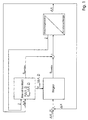
- Fig. 1 shows a schematic representation of Quality control, to determine the for the current process state required ultrasonic power P a table is used in which the for each Process state belonging ultrasound powers P in Dependence on the deformation of the wire and the Gradients of wire deformation ⁇ x are included (method 1). This table is created by experienced technologists and can always be adapted to new knowledge.
- One for that parallel controller is the desired course of the Deformation of the wire (different gradients for the respective operating states e.g. "Breaking up the Oxide layer ",” deforming ",” healing ”) as a setpoint.
- the table value P characteristic curve representing the current process status is provided together with the correction value P correction for controlling the ultrasound generator.
- the controller will only add very small correction values P correction to the table values P characteristic .
- the correction quantity P correction must not exceed a maximum value in order to rule out irreversible, spontaneous deformation of the wire.
- the values for the manipulated variable limitation P max ( ⁇ x, Z) are also based on the experience of technologists.
- a weighting factor for the table values can be derived from the course of the correction value for the manipulated variable, by means of which the table values are adapted to the current, material-dependent process parameters.
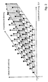
- Figure 2 shows such a table for controlling the bonding process. Output variables between the support points are interpolated.
- a neural network parameterizes the member functions of a set of rules, on the basis of which the bonds adapted to the current material data are carried out.
- the ultrasound power P fuzzy is calculated as a function of the impedance Z and the wire deformation ⁇ x using the fuzzy controller, using the rules that are not parameterized and parameterized in the learning phase, in order to determine the predetermined deformation profile to reach. This process is tolerant of fluctuations in material data and other environmental conditions influencing the process.
Landscapes
- Engineering & Computer Science (AREA)
- Mechanical Engineering (AREA)
- Quality & Reliability (AREA)
- Pressure Welding/Diffusion-Bonding (AREA)
- Wire Bonding (AREA)
Abstract
Description
- Fig. 1:
- ein schematisches Blockschaltbild für das Verfahren zur Qualitätskontrolle, bei dem die erfindungsgemäße Steuerung der Transducer-Bondkeil-Einheit mit Hilfe eines Kennlinienfeldes und eines Reglers zur Korrekturwertbildung erfolgt;
- Fig. 2:
- ein Kennlinienfeld der Ultraschall-Leistung in Abhängigkeit vom Gradienten der Drahtverformung und der Impedanzänderung der Transducer-Bondkeil-Einheit; und
- Fig. 3:
- ein schematisches Blockschaltbild für ein Verfahren zur Qualitätskontrolle, bei dem die benötigten Bondparameter automatisch erstellt werden.
- P
- Ultraschall-Leistung
- PKennlinie
- Tabellenwert für die Ultraschallleistung
- PKorrektur
- Korrekturwert für die Ultraschall-Leistung
- Pmax
- Maximalleistung
- PFuzzy
- berechnete Ultraschall-Leistung
- Δx
- Gradient der Drahtverformung
- x
- Absolutwert der Drahtverformung
- Z
- Impedanz
- CLK
- Taktsignal
Claims (7)
- Verfahren zur Qualitätskontrolle beim Ultraschall-Drahtbonden, bei dem die Verformung eines auf einer Kontaktfläche zu bondenden Drahtes ständig überwacht wird und eine Transducer-Bondkeil-Einheit und ein Ultraschall-Generator gebraucht werden, dadurch gekennzeichnet, daß zunächst eine den jeweils aktuellen Prozeßstand repräsentierende Tabelle der Ultraschall-Leistung als Funktion des Gradienten der Verformung des Drahtes, der Impedanz der Transducer-Bondkeil-Einheit sowie der aktuell erreichten Verformung des Drahtes erstellt und in einem Speicher abgelegt wird, daß einem Regler ein gewünschter Gradient der Verformung des Drahtes in Abhängigkeit vom jeweils aktuellen Prozeßstand als Sollwert vorgegeben wird, und daß die Stellgröße für den Ultraschall-Generator durch Addition von im Regler gebildeten Korrekturwerten zu den jeweils aktuellen Tabellenwerten berechnet wird.
- Verfahren nach Anspruch 1, dadurch gekennzeichnet, daß ein Maximalwert für den Korrekturwert vorgegeben wird.
- Verfahren nach Anspruch 1, dadurch gekennzeichnet, daß die Tabelle der Ultraschall-Leistung in Abhängigkeit von der Impedanzänderung der Transducer-Bondkeil-Einheit erstellt wird.
- Verfahren nach einem der Ansprüche 1 bis 3, dadurch gekennzeichnet, daß aus dem Verlauf des Korrekturwertes für die Stellgröße für die Ultraschall-Leistung ein Gewichtungsfaktor für die Tabellenwerte zu deren Adaption an die aktuellen werkstoffabhängigen Prozeßparameter abgeleitet wird.
- Verfahren nach einem der Ansprüche 1 bis 4, dadurch gekennzeichnet, daß die Tabelle der Ultraschall-Leistung in einer Lernphase selbsttätig erstellt wird, wobei zusätzlich lediglich die den einzelnen Bonds zugeschrieben Qualitätsparameter manuell vorgegeben werden.
- Verfahren nach Anspruch 5, dadurch gekennzeichnet, daß mit den in der Lernphase mit Hilfe eines neuronalen Netzes parametrisierten Regeln mit Hilfe eines Fuzzy-Reglers die Ultraschall-Leistung als Funktion der Impedanz und des Gradienten der Verformung des Drahtes errechnet wird.
- Verfahren zur Qualitätskontrolle beim Ultraschall-Drahtbonden, bei dem die Verformung eines auf einer Kontaktfläche zu bondenden Drahtes ständig überwacht wird und eine Transducer-Bondkeil-Einheit und ein Ultraschall-Generator gebraucht werden, dadurch gekennzeichnet, daß in einer Lernphase eine den jeweils aktuellen Prozeßzustand repräsentierende Tabelle der Ultraschall-Leistung als Funktion des Gradienten der Verformung des Drahtes, der Impedanz der Transducer-Bondkeil-Einheit sowie der aktuell erreichten Verformung des Drahtes mit Hilfe der durch ein neuronales Netz parametrisierten Regeln erstellt wird, wobei die für den jeweils aktuellen Prozeßzustand benötigte Ultraschall-Leistung mit Hilfe eines Fuzzy-Reglers errechnet wird und daß durch das neuronale Netz bestimmte Ultraschallpegel mit einem fest vorgegebenen Takt auf den Ultraschall-Generator geschaltet werden.
Applications Claiming Priority (3)
| Application Number | Priority Date | Filing Date | Title |
|---|---|---|---|
| DE19745131 | 1997-10-13 | ||
| DE19745131 | 1997-10-13 | ||
| PCT/DE1998/002999 WO1999019107A1 (de) | 1997-10-13 | 1998-10-07 | Verfahren zur qualitätskontrolle |
Publications (2)
| Publication Number | Publication Date |
|---|---|
| EP1023139A1 EP1023139A1 (de) | 2000-08-02 |
| EP1023139B1 true EP1023139B1 (de) | 2004-01-14 |
Family
ID=7845369
Family Applications (1)
| Application Number | Title | Priority Date | Filing Date |
|---|---|---|---|
| EP98961003A Expired - Lifetime EP1023139B1 (de) | 1997-10-13 | 1998-10-07 | Verfahren zur qualitätskontrolle |
Country Status (5)
| Country | Link |
|---|---|
| US (1) | US6308881B1 (de) |
| EP (1) | EP1023139B1 (de) |
| AU (1) | AU1660199A (de) |
| DE (2) | DE59810602D1 (de) |
| WO (1) | WO1999019107A1 (de) |
Cited By (1)
| Publication number | Priority date | Publication date | Assignee | Title |
|---|---|---|---|---|
| DE102007054626A1 (de) | 2007-11-12 | 2009-05-14 | Hesse & Knipps Gmbh | Verfahren und Vorrichtung zum Ultraschallbonden |
Families Citing this family (11)
| Publication number | Priority date | Publication date | Assignee | Title |
|---|---|---|---|---|
| DE19902827C1 (de) * | 1999-01-15 | 2000-06-08 | Hielscher Gmbh | Verfahren zum Konstanthalten der mittleren Spaltbreite zwischen einer Sonotrode eines Ultraschall-Systems und einem als Gegenwerkzeug ausgebildeten Schneidwerkzeugs einer Ultraschall-Schneideinrichtung |
| KR100896828B1 (ko) * | 2001-10-26 | 2009-05-12 | 외르리콘 어셈블리 이큅먼트 아게, 슈타인하우젠 | 와이어 본더를 보정하는 방법 |
| KR20030066344A (ko) * | 2002-02-01 | 2003-08-09 | 에섹 트레이딩 에스에이 | 와이어본더로 접합시에 최적의 접합 파라미터들을결정하기 위한 방법 |
| EP1343201A1 (de) * | 2002-03-08 | 2003-09-10 | F & K Delvotec Bondtechnik GmbH | "Verfahren und Anordnung zur Herstellung und Qualitätsprüfung einer Drahtbondverbindung" |
| US6857553B1 (en) * | 2002-04-17 | 2005-02-22 | The United States Of America As Represented By The United States Department Of Energy | Method and apparatus for in-process sensing of manufacturing quality |
| RU2253555C2 (ru) * | 2003-08-12 | 2005-06-10 | Федеральное государственное унитарное предприятие "Научно-исследовательский и конструкторский институт энерготехники им. Н.А. Доллежаля" | Способ контроля качества сварных и паяных соединений разнородных материалов |
| DE102006020417B4 (de) | 2006-04-26 | 2008-10-02 | Herrmann Ultraschalltechnik Gmbh & Co. Kg | Vorrichtung zum Bearbeiten von Werkstücken mittels Ultraschall |
| DE102006043605B3 (de) * | 2006-09-16 | 2008-03-27 | Stapla Ultraschalltechnik Gmbh | Verfahren zur Qualitätsüberwachung beim Ultraschallschweißen |
| RU2721338C1 (ru) * | 2018-12-20 | 2020-05-19 | Акционерное общество "Научно-производственное предприятие "Пульсар" | Способ определения качества монтажа подложек во время ультразвуковой микросварки |
| DE102019109263B4 (de) * | 2019-04-09 | 2021-11-18 | Lisa Dräxlmaier GmbH | Verfahren, eine Messvorrichtung und eine Ultraschallschweißanlage zum zerstörungsfreien Prüfen einer Qualität einer Ultraschallschweißung |
| CN117548806B (zh) * | 2023-12-26 | 2025-11-25 | 上海骄成超声波技术股份有限公司 | 焊接控制方法和系统 |
Family Cites Families (12)
| Publication number | Priority date | Publication date | Assignee | Title |
|---|---|---|---|---|
| DE217454C (de) | ||||
| US4341574A (en) * | 1980-08-25 | 1982-07-27 | Texas Instruments Incorporated | Ultrasonic bond energy monitor |
| JPS5950536A (ja) * | 1982-09-16 | 1984-03-23 | Toshiba Corp | ワイヤボンデイング装置 |
| DD217454A1 (de) * | 1983-04-29 | 1985-01-16 | Zentrum F Forschung U Technolo | Verfahren zur steuerung von us-schweissvorgaengen |
| DE3667930D1 (de) * | 1985-07-12 | 1990-02-08 | Siemens Ag | Verfahren zum regeln des prozessverlaufes und zur qualitaetskontrolle beim ultraschallschweissen von werkstuecken. |
| US4815001A (en) * | 1986-05-30 | 1989-03-21 | Crestek, Inc. | Ultrasonic wire bonding quality monitor and method |
| GB8826488D0 (en) * | 1988-11-11 | 1988-12-14 | Emhart Deutschland | Quality control for wire bonding |
| DE69216761T2 (de) * | 1991-10-30 | 1997-07-03 | F & K Delvotev Bondtechgmbh | Steuerungssystem |
| US5357423A (en) * | 1993-02-22 | 1994-10-18 | Kulicke And Soffa Investments, Inc. | Apparatus and method for automatically adjusting power output of an ultrasonic generator |
| JP3425492B2 (ja) * | 1995-08-18 | 2003-07-14 | 松下電器産業株式会社 | 半導体実装方法およびその装置 |
| JP3504448B2 (ja) * | 1996-10-17 | 2004-03-08 | 株式会社ルネサステクノロジ | 半導体装置 |
| US5894981A (en) * | 1996-11-27 | 1999-04-20 | Orthodyne Electronics Corporation | Integrated pull tester with an ultrasonic wire bonder |
-
1998
- 1998-10-07 WO PCT/DE1998/002999 patent/WO1999019107A1/de not_active Ceased
- 1998-10-07 AU AU16601/99A patent/AU1660199A/en not_active Abandoned
- 1998-10-07 DE DE59810602T patent/DE59810602D1/de not_active Expired - Lifetime
- 1998-10-07 DE DE19881469T patent/DE19881469D2/de not_active Ceased
- 1998-10-07 EP EP98961003A patent/EP1023139B1/de not_active Expired - Lifetime
-
2000
- 2000-04-13 US US09/548,761 patent/US6308881B1/en not_active Expired - Fee Related
Cited By (3)
| Publication number | Priority date | Publication date | Assignee | Title |
|---|---|---|---|---|
| DE102007054626A1 (de) | 2007-11-12 | 2009-05-14 | Hesse & Knipps Gmbh | Verfahren und Vorrichtung zum Ultraschallbonden |
| EP2385545A2 (de) | 2007-11-12 | 2011-11-09 | Hesse & Knipps GmbH | Verfahren und Vorrichtung zum Ultraschallbonden |
| US8783545B2 (en) | 2007-11-12 | 2014-07-22 | Hesse Gmbh | Method for quality control during ultrasonic |
Also Published As
| Publication number | Publication date |
|---|---|
| EP1023139A1 (de) | 2000-08-02 |
| WO1999019107A1 (de) | 1999-04-22 |
| DE59810602D1 (de) | 2004-02-19 |
| AU1660199A (en) | 1999-05-03 |
| DE19881469D2 (de) | 2000-11-30 |
| US6308881B1 (en) | 2001-10-30 |
Similar Documents
| Publication | Publication Date | Title |
|---|---|---|
| DE3113250C2 (de) | Verfahren zur Regelung des Schweißstroms bei Widerstandsschweißungen | |
| DE10324094B3 (de) | Verfahren zum Verschweißen von Teilen | |
| DE3711771C2 (de) | ||
| WO1999019107A1 (de) | Verfahren zur qualitätskontrolle | |
| DE3618080C2 (de) | ||
| DE69708519T2 (de) | Punktschweissvorrichtung und ein Verfahren zur Kontrolle der Vorrichtung | |
| EP0896263B1 (de) | Verfahren und Schaltungsanordnung zur Ermittlung optimaler Reglerparameter für eine Drehzahlregelung | |
| DE19622374B4 (de) | Verfahren und Vorrichtung zur Regelung der Zerspannungsleistung einer Säge | |
| DE102015120824A1 (de) | Betriebsverfahren für einen Ultraschalldrahtbonder | |
| DE3243549A1 (de) | Regelvorrichtung fuer die volldigitalisierte drehzahlreglung einer naehmaschine bzw. eines naehautomaten | |
| DE102008001774A1 (de) | Verfahren zum Betrieb einer Werkzeugmaschine, insbesondere einer Handwerkzeugmaschine | |
| DE3035098A1 (de) | Regelverfahren fuer schneiddraht-funkenerosion | |
| EP1641587B1 (de) | Verfahren und vorrichtung zur gewinnung von informationen zur beurteilung der qualität einer widerstandsschweissverbindung und/oder zur steuerung oder regelung eines widerstandsschweissverfahrens | |
| EP1625911A1 (de) | Drahtbonder mit einer Kamera, einer Bildverarbeitungseinrichtung, Speichermittel und Vergleichermittel und Verfahren zum Betrieb eines solchen | |
| DE3303660A1 (de) | Verfahren und vorrichtung zur edm-elektroden-positionierung | |
| DE10144286C1 (de) | Verfahren zur Beurteilung der Qualität einer Schweißverbindung | |
| EP1343201A1 (de) | "Verfahren und Anordnung zur Herstellung und Qualitätsprüfung einer Drahtbondverbindung" | |
| DE10334478B4 (de) | Verfahren und Vorrichtung zum Widerstandsschweißen | |
| DE10137977C1 (de) | Punktschweiß-Steuervorrichtung | |
| EP4204175B1 (de) | Verfahren zum steuern oder regeln der vorschubgeschwindigkeit eines drahts aus abschmelzendem material bei einem laserlöt- oder laserschweissverfahren sowie laserlöt- oder laserschweissvorrichtung zur durchführung eines solchen verfahrens | |
| EP0489130B1 (de) | Verfahren zur korrektur von regelparametern einer prozessregelung, insbesondere zur erhaltung des dynamikbereiches (regelbereiches) der prozessregelung während des prozessverlaufes und vorrichtung zur durchführung des verfahrens | |
| EP3355343A1 (de) | Verfahren zur herstellung von drahtbondverbindungen und vorrichtung zur durchführung des verfahrens | |
| DE4203190C1 (en) | Regulation and quality assessing of welding esp. spot welding - has ultrasonic detecting probe attached to welding electrode to record noise emission level at weld location | |
| DE3038747T1 (de) | Wire-cut electrical discharge machine | |
| WO2021019019A1 (de) | SCHWEIßSYSTEM UND SCHWEIßVERFAHREN |
Legal Events
| Date | Code | Title | Description |
|---|---|---|---|
| PUAI | Public reference made under article 153(3) epc to a published international application that has entered the european phase |
Free format text: ORIGINAL CODE: 0009012 |
|
| 17P | Request for examination filed |
Effective date: 20000401 |
|
| AK | Designated contracting states |
Kind code of ref document: A1 Designated state(s): DE FR GB SE |
|
| GRAH | Despatch of communication of intention to grant a patent |
Free format text: ORIGINAL CODE: EPIDOS IGRA |
|
| GRAH | Despatch of communication of intention to grant a patent |
Free format text: ORIGINAL CODE: EPIDOS IGRA |
|
| GRAA | (expected) grant |
Free format text: ORIGINAL CODE: 0009210 |
|
| AK | Designated contracting states |
Kind code of ref document: B1 Designated state(s): DE FR GB SE |
|
| REG | Reference to a national code |
Ref country code: GB Ref legal event code: FG4D Free format text: NOT ENGLISH |
|
| REF | Corresponds to: |
Ref document number: 59810602 Country of ref document: DE Date of ref document: 20040219 Kind code of ref document: P |
|
| PG25 | Lapsed in a contracting state [announced via postgrant information from national office to epo] |
Ref country code: SE Free format text: LAPSE BECAUSE OF FAILURE TO SUBMIT A TRANSLATION OF THE DESCRIPTION OR TO PAY THE FEE WITHIN THE PRESCRIBED TIME-LIMIT Effective date: 20040414 |
|
| GBT | Gb: translation of ep patent filed (gb section 77(6)(a)/1977) | ||
| ET | Fr: translation filed | ||
| PLBE | No opposition filed within time limit |
Free format text: ORIGINAL CODE: 0009261 |
|
| STAA | Information on the status of an ep patent application or granted ep patent |
Free format text: STATUS: NO OPPOSITION FILED WITHIN TIME LIMIT |
|
| 26N | No opposition filed |
Effective date: 20041015 |
|
| PGFP | Annual fee paid to national office [announced via postgrant information from national office to epo] |
Ref country code: FR Payment date: 20101019 Year of fee payment: 13 |
|
| PGFP | Annual fee paid to national office [announced via postgrant information from national office to epo] |
Ref country code: GB Payment date: 20101007 Year of fee payment: 13 |
|
| REG | Reference to a national code |
Ref country code: DE Ref legal event code: R082 Ref document number: 59810602 Country of ref document: DE Representative=s name: WICKORD, WIRO, M.SC. (USA) DIPL.-ING. DR.-ING., DE Ref country code: DE Ref legal event code: R082 Ref document number: 59810602 Country of ref document: DE Representative=s name: WIRO WICKORD, DE |
|
| GBPC | Gb: european patent ceased through non-payment of renewal fee |
Effective date: 20111007 |
|
| REG | Reference to a national code |
Ref country code: FR Ref legal event code: ST Effective date: 20120629 |
|
| PG25 | Lapsed in a contracting state [announced via postgrant information from national office to epo] |
Ref country code: GB Free format text: LAPSE BECAUSE OF NON-PAYMENT OF DUE FEES Effective date: 20111007 Ref country code: FR Free format text: LAPSE BECAUSE OF NON-PAYMENT OF DUE FEES Effective date: 20111102 |
|
| PGFP | Annual fee paid to national office [announced via postgrant information from national office to epo] |
Ref country code: DE Payment date: 20121015 Year of fee payment: 15 |
|
| REG | Reference to a national code |
Ref country code: DE Ref legal event code: R082 Ref document number: 59810602 Country of ref document: DE Representative=s name: WICKORD, WIRO, M.SC. (USA) DIPL.-ING. DR.-ING., DE |
|
| REG | Reference to a national code |
Ref country code: DE Ref legal event code: R082 Ref document number: 59810602 Country of ref document: DE Representative=s name: WICKORD, WIRO, M.SC. (USA) DIPL.-ING. DR.-ING., DE Effective date: 20130213 Ref country code: DE Ref legal event code: R082 Ref document number: 59810602 Country of ref document: DE Representative=s name: WICKORD, WIRO, M.SC. (USA) DIPL.-ING. DR.-ING., DE Effective date: 20120213 Ref country code: DE Ref legal event code: R081 Ref document number: 59810602 Country of ref document: DE Owner name: HESSE GMBH, DE Free format text: FORMER OWNER: HESSE & KNIPPS GMBH, 33100 PADERBORN, DE Effective date: 20130213 |
|
| REG | Reference to a national code |
Ref country code: DE Ref legal event code: R119 Ref document number: 59810602 Country of ref document: DE Effective date: 20140501 |
|
| PG25 | Lapsed in a contracting state [announced via postgrant information from national office to epo] |
Ref country code: DE Free format text: LAPSE BECAUSE OF NON-PAYMENT OF DUE FEES Effective date: 20140501 |